What are Traffic Lines for?
If you want to get influence lines for any calculated values in sections and nodes of the model, you must first define the movement paths for a unit load in the preprocessor. The Traffic Lines tool allows you to do this.
How it works
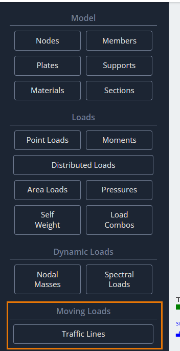
The button to open the Traffic Lines parameter window can be found on the left-side interface panel in the Moving Loads section.
After clicking this button, the Traffic Lines dialog box will appear in the modeling area to define its parameters.
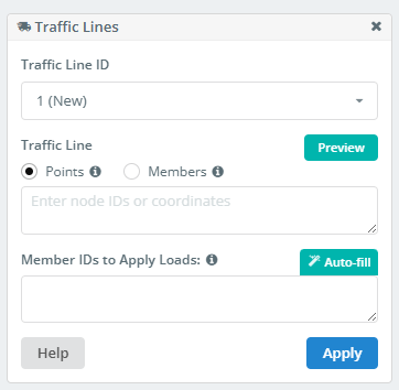
Traffic Line ID
A list of all Traffic Lines defined in the model. You can select, edit, or delete one if it’s no longer needed.
A Traffic Line is a line in space. This line does not have to be straight. There are two methods for defining such a line. The first method uses existing points in the model or direct coordinate input for the line’s vertices.
Defining Traffic Lines using Points
Points
If the traffic line is a straight line, it is sufficient to define two points: the start and the end.
- To define by points, specify the node IDs in this format:
1;4 - When defining points by coordinates, they must be entered in this format:
0,2.3,0; 210,2.3,0
Member IDs to Apply Loads
To obtain the values of the factors being studied, a series of static analyses must be performed. The program needs to know where to place the unit force in each static loading. To do this, you must define a set of members.
The unit force will be applied and load cases will be created at the intersection/superposition points of these members with the traffic line. This process occurs automatically when the analysis is run.
The more intersections you have, the more accurate the influence line you will get. However, too many intersections will lead to long calculation times. Choose a reasonable number.
- The list of members is entered in the format:
1, 2, 3, 4 - Use “Auto-fill”. The list will be defined automatically and can then be edited manually.
Defining Traffic Lines using Members
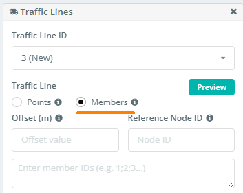
Alternatively, you can define the traffic line path using a chain of members. This approach is particularly useful when the intended path is curved and follows the curvature of a structural member (like a bridge girder, etc.).
To do this, enter the members for the path into the list in the format: 1;2;7;4;5;12… or 1-25 if the members in the chain are sequential.
Offset
This field defines the offset distance from the specified chain of members. Therefore, it’s useful if the traffic line needs to follow the shape of the member chain but not its exact position.
Reference Node ID
Here, you will specify the ID of the node that defines the direction of the offset for the traffic line from the specified member chain.
Finally, after defining all parameters, press Apply to add the traffic line to the list.
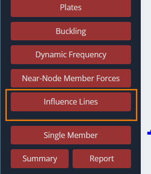
Influence Lines
After running the analysis on the model with defined traffic lines, you can analyze the results as influence lines. To do this, you must find the Influence Lines button on the left-side interface panel in the post-processor.
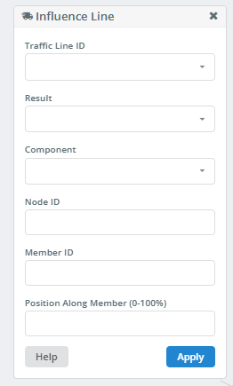
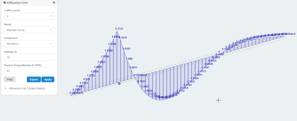
After clicking this button, the Influence Line dialog box will appear in the modeling area to define its parameters.
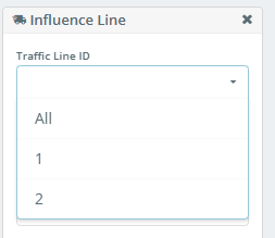
Traffic Line ID
In this dropdown list, you can select the ID of the traffic line for which the influence line will be built. You can also build influence lines for all traffic lines by selecting “All”.
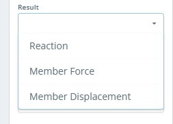
Result
This list allows you to select the result type for building the influence line.
Component
This list shows the resulting values for reactions at supported nodes, or forces and displacements in member sections. The contents of this list depend on the selection in the “Result” list.
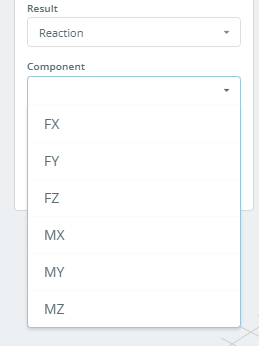
If “Result” is set to Reaction, the list will look like this:
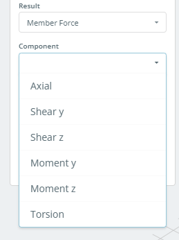
If “Result” is set to Member Force, the list will look like this:
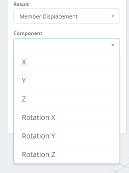
If “Result” is set to Member Displacement, the list will look like this:
Node ID
If “Result” is set to Reaction, you must specify the ID of the supported node for which the influence line will be built.
Member ID
If “Result” is set to Member Force or Member Displacement, you must specify the member ID for which the influence line will be built.
Position Along Member (0-100%)
This field specifies the position of the section on the member for which the influence line will be built. The section’s coordinate is set as a percentage of the total member length, measured from the start of the member.
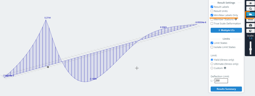
After clicking the Apply button, the influence line is graphically plotted on the model.
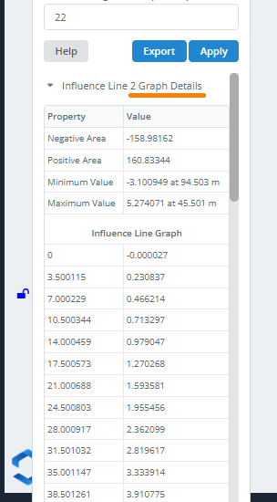
The Export button allows you to save the Influence Line data to your computer as an Excel file.
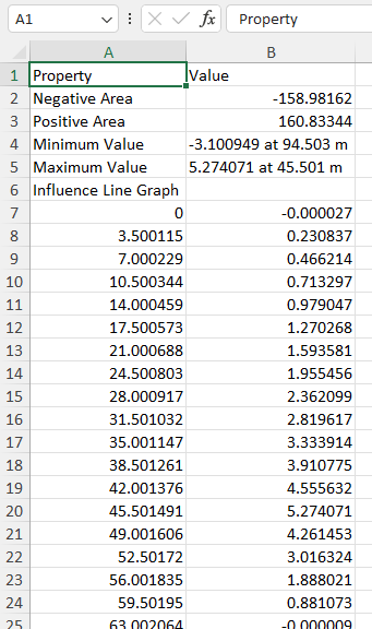
You can also get this information by clicking on Graph Details.
To display only the Min/Max values on the graph, use the following settings in the right-side menu: