On this page, you will find:
- Model Setup
- Opening the Builder
- Defining Grillage
- Sections, Supports and Loads
- Generation and Editing
- Analysis and Results
Auto Diaphragm Strut and Tie builder
Strut-and-tie (diaphragm grillage) models can be generated using SkyCiv’s Strut & Tie Builder. The tool converts selected plate elements into an equivalent system of struts and ties, allowing for complex diaphragm behaviour to be represented as a simplified axial-force system.
After solving, results can be reviewed to validate the behaviour of the generated system. Key outputs include axial forces, displacements, and stress distribution within the members. These results can be visualised directly in the graphical interface or exported as CSV files or PDF analysis reports.

Model Prerequisites
Skycivs strut-and-tie builder operates directly from plate elements, meaning a valid plate model must exist before the tool can be used. The diaphragm region must be defined using plates, as plate geometry forms the basis of generated grillage.
Isolating Diaphragm from an Existing Model
Before generating the strut and tie grillage, isolate the diaphragm from the full structural model. This reduces unnecessary geometry, improving clarity of strut and tie analysis making load paths easier to interpret. This can be achieved through either manual selection or by using predefined elevations.
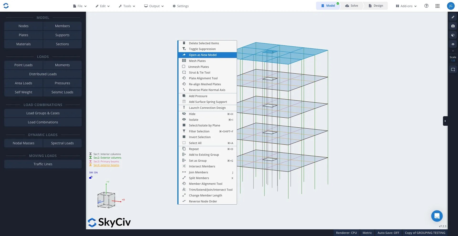
Option 1. Manual selection
The specified region can be selected directly by holding Cmd (Mac) or Ctrl (windows) and dragging across the desired plate element. Once highlighted (desired region will appear blue) right click and select “Open as New Model” to extract level into seperate model.
- Hold Cmd (Mac) / Ctrl (Windows) and drag to select region
- Right-click the selection
- Click “Open as New Model”
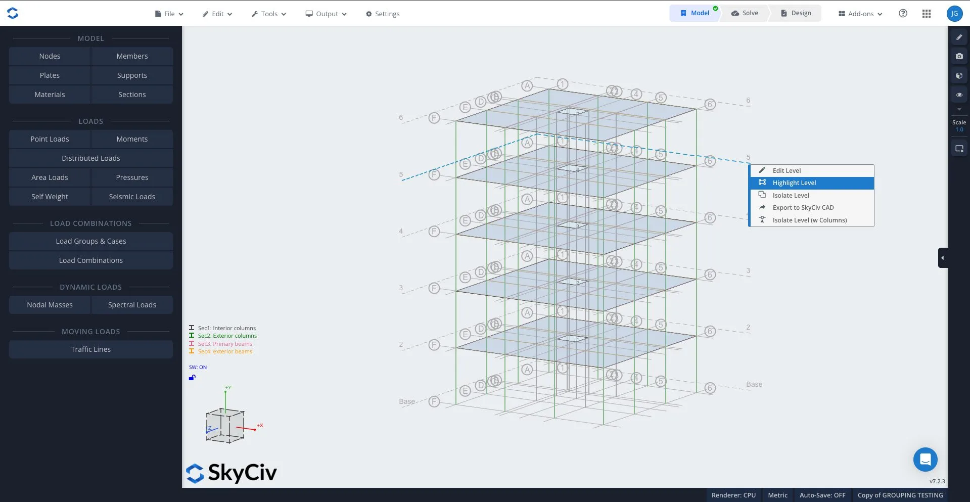
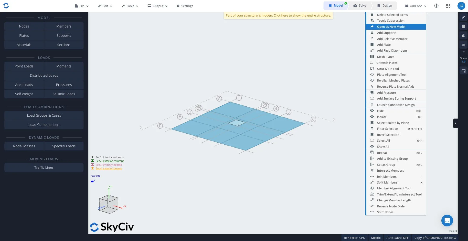
Option 2.Using Elevations (optional)
For multi-story structures, elevations are a more structured way to isolate desired regions. Using Gridlines and elevations tool, a specific floor level can be selected or isolated and once highlighted (desired region will appear blue) right click and select “Open as New Model” to extract level into seperate model.
- Open Gridlines and Elevations tool
- Select desired floor level
- Click isolate level
- Click highlight level
- Right-click “Open as New Model”
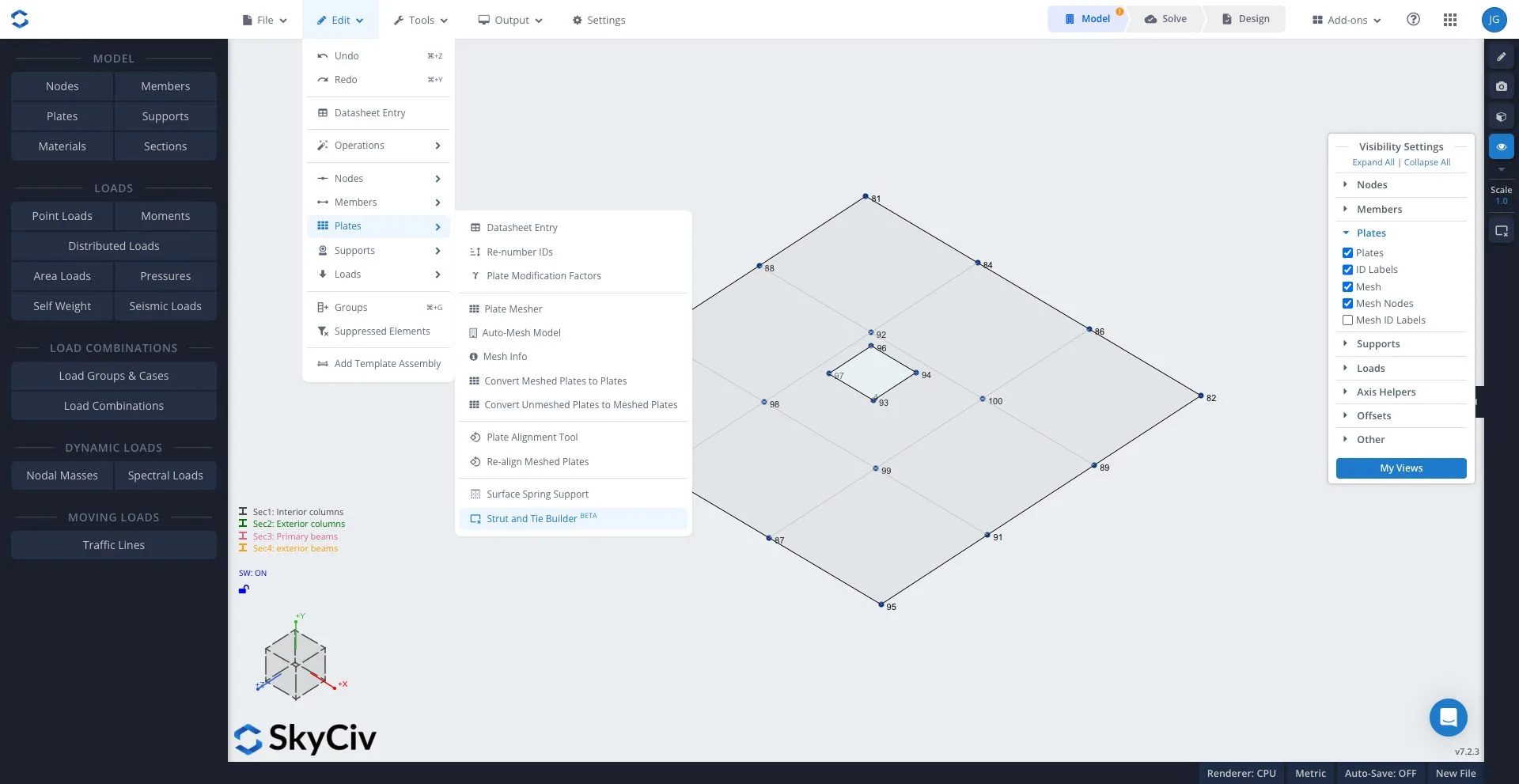
How To use Auto Diaphragm
To open the Strut and Tie Builder, you can either:
- Edit > plates > strut and tie builder (BETA)
- Right Click a plate and click Strut and Tie Builder
- Open the right Toolbox Menu, and search Strut. Note: you can pin this or create a keyboard shortcut
This will launch the Strut & Tie Builder on your left panel. It will also import your Topping Thickness and the Plate ID if a selected plate was right clicked:

Automatically adding your Grillage System
1. Source
To begin creating your grillage system, the first step is defining your source. This tells the tool which part of the model will be converted into your strut and tie grillage. Sources are defined by 5 key elements:
- Floor level (Y axis) – used for horizontal diaphragms at a given elevation
- Wall plane – helpful for vertical plates typically walls
- Constant Axis (x or z) – allows for selection across a global axis
- Coordinate – defines a region based upon location in model
- Plate IDs – lets you manually nominate a plate ID
2. Grillage Parameters

Once the source has been defined, the next step is setting grillage parameters. This controls how the auto diaphragm generates the strut and tie layout.
- Max spacing (m) – controls spacing between grillage members and model density
- Topping thickness (mm) – defines the thickness of diaphragm used in model, is based off plate thickness
- Build coverage from existing meshed plates – uses existing plate meshes to help guide generated grillage member layout
3. Sections

This step allows for you to assign pre-made sections to the generated grillage members. for most cases, it’s recommended to leave this section blank and allow for the tool to automatically create your sections. The automatic generation uses defined grillage settings to create optimal members without requiring manual inputs.
Automatic section generation
When tie and strut section are left blank the tool generates member properties from grid spacing plate thickness or topping thickness and default width factors. Members properties are defined by:
Tie members:
- width = 0.75 x grid spacing
- depth = plate thickness
Strut members:
- width = 0.53 x grid spacing
- depth = plate thickness
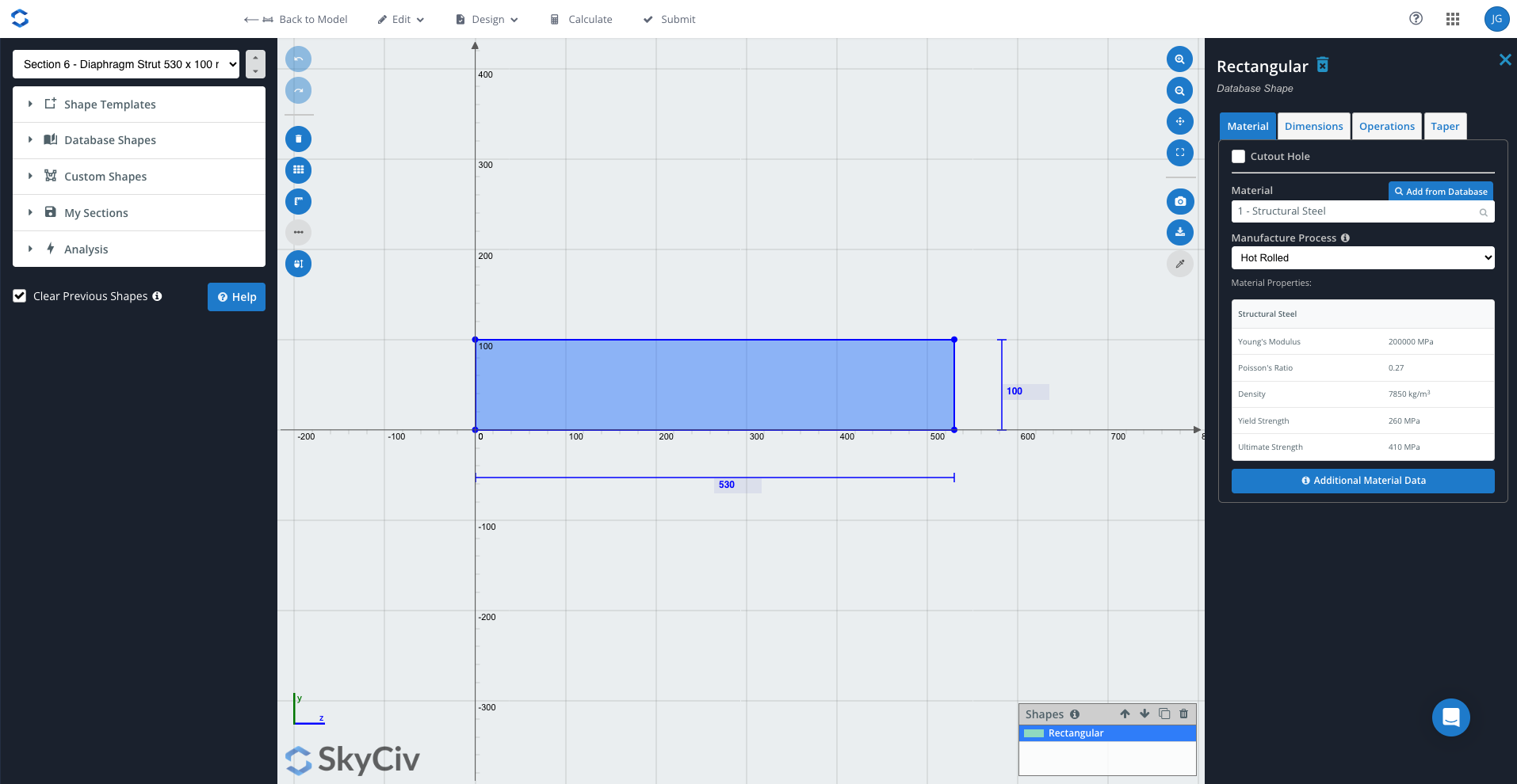
These are used to generate equivalent auto diaphragm grillages, this is visually displayed by SkyCivs Section Builder:

This allows you to
- inspect automatically generated sections
- confirm consistency with your models inputs
- adjust properties as needed
Editing Width factors
Width factors define the width of each members section in relation to grillage spacing.
The width factors (0.75, 0.53) are based upon Hrennikoff’s (1941 framework method), where a plate is represented by an equivalent grillage with matching stiffness. These values are used to provide a realistic approximation of the plate behaviour through capturing the orthogonal members primary load-carrying behaviour, while diagonal members represent shear transfer and load redistribution. Together, these factors ensure the generated grillage behaves consistently with the original plate.
4. Adding your Supports (optional)

Supports can automatically be added automatically assigned to nodes where grillage members intersect. Two main support types can be applied
- RFRRRR – fixed vertical restraint
- RSRRRR – spring support in vertical direction
When using spring supports, stiffness can be user defined (kN/m) to control vertical flexibility within the system. for most cases, it’s recommended that spring supports are added over fixed supported. This is because the generated auto-diaphragm acts as a pin supported truss system where axial forces are carried. Fully restraining the system introduces artificial stiffness which does not reflect intended behaviour.
5. Total lateral loads (optional)

Global lateral loads can be added directly to generated grillage. This allows for the introduction of overall forces without needing to manually apply. Your specified lateral loads are distributed evenly across generated nodes in grillage, allowing system to developed loads paths through your strut and tie.
- X (kN) – load forces in global X direction
- Y (kN) – load forces in global Y direction
- Z (kN) – load forces in global Z direction
- Load groups – assign load case
Creating and Editing Auto Diaphragm Model

Once inputs have been defined, the following tools allow for control of how grillage is created, modified and managed.
Generation and editing of model
This generates your auto-diaphragm grillage based on inputs and visually displays this on model. This tool supresses your plate and converts it into an equivilant grillage by:
- creating nodes at grid intersections
- generates strut and tie members
- Distributes loads across nodes

Undo Last generation
If created grillage needs revision, this tool reverts model back to it’s previous state before generation. This is useful when testing different parameters or refining inputs.
Suppress Plates and Meshed plates
Hides original plate elements at specified elevations or by plate IDs
Remove existing grillage on this plate
Deletes generated grillage for a selected plate region or elevation. Allows for the regeneration of specified grillages without affecting the whole model.
Reset to original
Removes all generated grillage elements and restores to original plate based model.
Running Analysis and Viewing Results
Solving and Interpreting Results
Once the grillage has been generated the model is ready to be analysed.
This can be done by going to the top right of the page, selecting solve and allowing the solver to run. Once complete, results are now ready to be reviewed to confirm system is working as an intended strut-and-tie model.

Step 1. Check bending moments
Before review of results it’s important to review the bending moment diagram. In the analysis tab on the left click moment to view this. For a correctly behaving strut and tie model bending moments should be zero throughout the structure, this is because the generated grillage behaves as a pin jointed truss system. Where members carry tension or compression only, no moments transfer between members. If bending moments are generated this may indicate issues within the system such as:
- Excessive restraints on columns (over-constrained supports or columns)
- Incorrect support configuration
- Poor load application
- connectivity or model geometry issues.

Step 2. Review axial forces
Once the sanity check is completed confirming correct behaviour, the next step is to review axial forces. Which are the primary results of interest in a strut-and-tie model. Navigate on the left hand side to the results panel to review axial forces, this displays the axial force diagram.
THIS IS INCOMPLETE NEED TO WRITE THIS
Visualising axial forces
- hold S and scroll to scale forces on diagram
- Positive values indicate tension
- negative values indicate compressions
Axial force diagram should show
- Load paths to the supports
- Redistribution
