Add members quickly by angle or relative position by tapping ‘R’
In addition to the traditional modelling methods in Structural 3D, SkyCiv’s Relative Member function gives users yet another way to model their structures quicker and easier.
To use the Relative Member function, first select a node and either:
a) press ‘R’, or
b) Right Click node and select Add Relative Member.
This will bring up a small pop-up that can me moved around the model space to best assist viewing as is shown below:
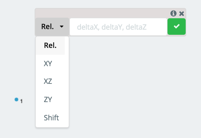
From here, use the dropdown to select the method of adding the relative member and the input field to put in the required data. There are two main methods (Rel, Length/Angle) to adding relative members, which will be explored below:
Adding a Relative Member using Global Axis Projection
The “Rel.” method is the default method to adding a relative member. The three values shown in the input field (deltaX, deltaY, deltaZ) correspond to the change in position from the selected node to the newly generated node. This is particularly useful for modeling in 3D space when you know the change in X, Y, and Z between the end points.
Example:
If the selected node, say Node 1, is at the position (0,1,4) and you wanted to generate a member from Node 1 to a node at (10,12,8), say Node 2, you would put (10,11,4) as the values for (deltaX, deltaY, deltaZ). The projection to the new node will show as a dotted line:
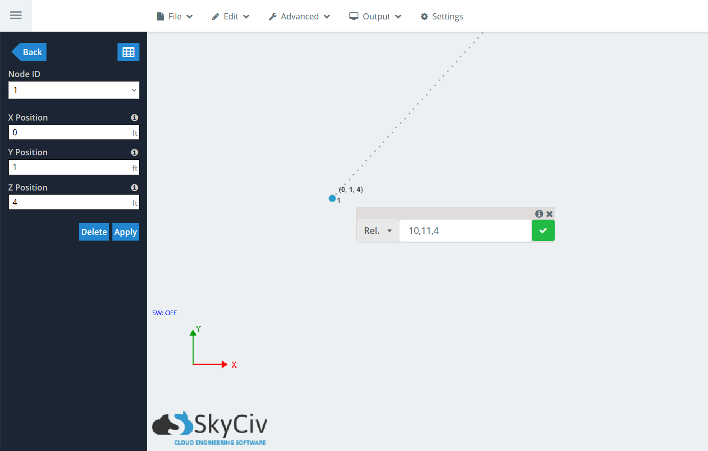
Click the green check mark, or hit Enter, to accept the generation of the member. The relative member window will stay up so you can chain multiple members in a row. If you choose to generate another member, the origin node will be Node 2, so the delta values will be relative to it, not Node 1.
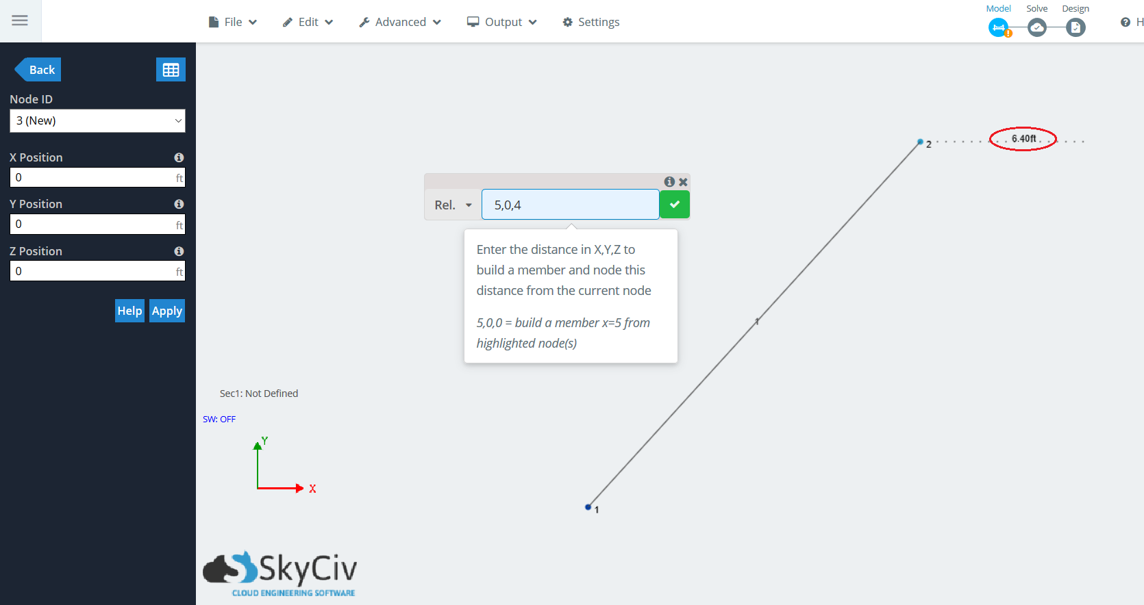
Note in the image below, that while the dotted projection line is showing, it will display the member length, similar to when using the pen tool:
Adding a Relative Member using Angle and Length
This method allows users to quickly enter a member length and angle for a quick angled member. It is useful when modelling in 2D space and you know the angle and length of the member you wish to create. You can create a member from a selected node by inputting the angle from the horizontal (going counterclockwise) and the length of the member.
Because there are an infinite number of planes that can be used to generate a node in 3D space, users have the ability to use this method with one of the three global axis planes: XY, YZ, and XZ. The two values shown in the input field of these three options (angle, length) correspond to the angle in degrees from the horizontal and the length of the member, respectively.
Example:
Lets say you want to generate an angled member in the XY plane originating from a node at (o,o,o), say Node 1. You know that the member sits at a 30 degree angle from the horizontal, in this case the X axis, and is 12 feet long. Select the node, press ‘R’ to bring up the Relative Member function. Click the dropdown and go to “XY”. Put in (30,12) in the input field, the projection will again show as a dotted line:
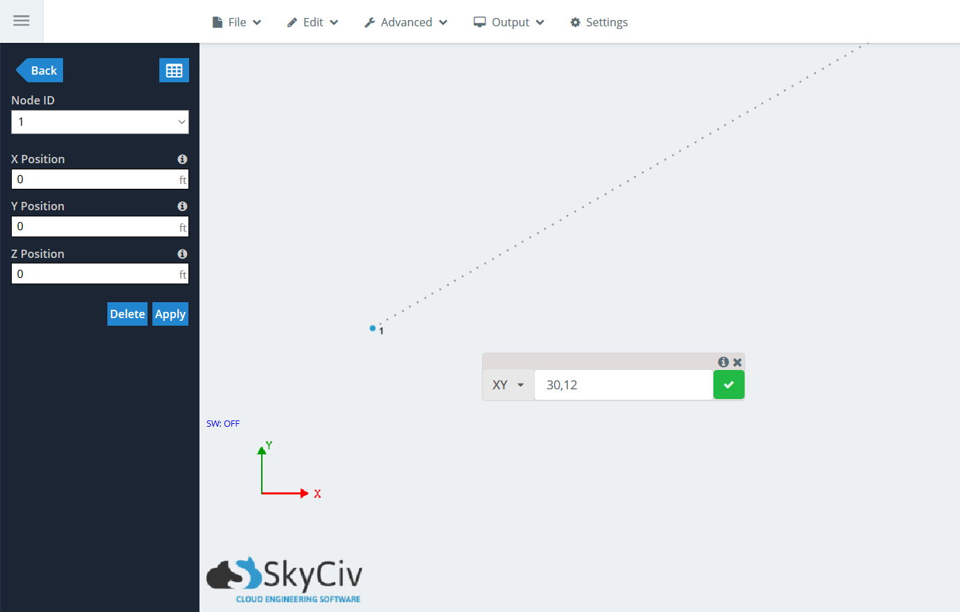
Click the green check mark, or hit Enter, to accept the generation of the member. The relative member window will stay up so you can chain multiple members in a row. If you choose to generate another member, the origin node will be Node 2, so the delta values will be relative to it, not Node 1.
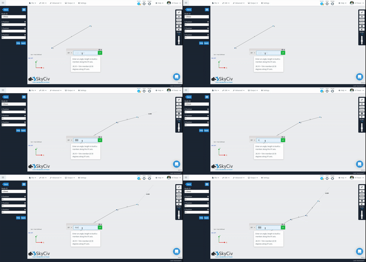
Adding Multiple Relative Members at the Same Time
The same Relative Member member function can not only be used to generate single members, but multiple at the same time. The workflow is the same, except users can select multiple nodes that they wish to generate relative members from. These nodes do not have to lie in the same plane and can be anywhere within the project.
Example:
For this example, lets look a simple elevated platform which can be very easily generated using Assembly Templates within Structural 3D. Start by clicking Ctrl and dragging from right to left to select the topmost “floor” of nodes and members.
Note: The Relative Member function only generates members from nodes, not from members.
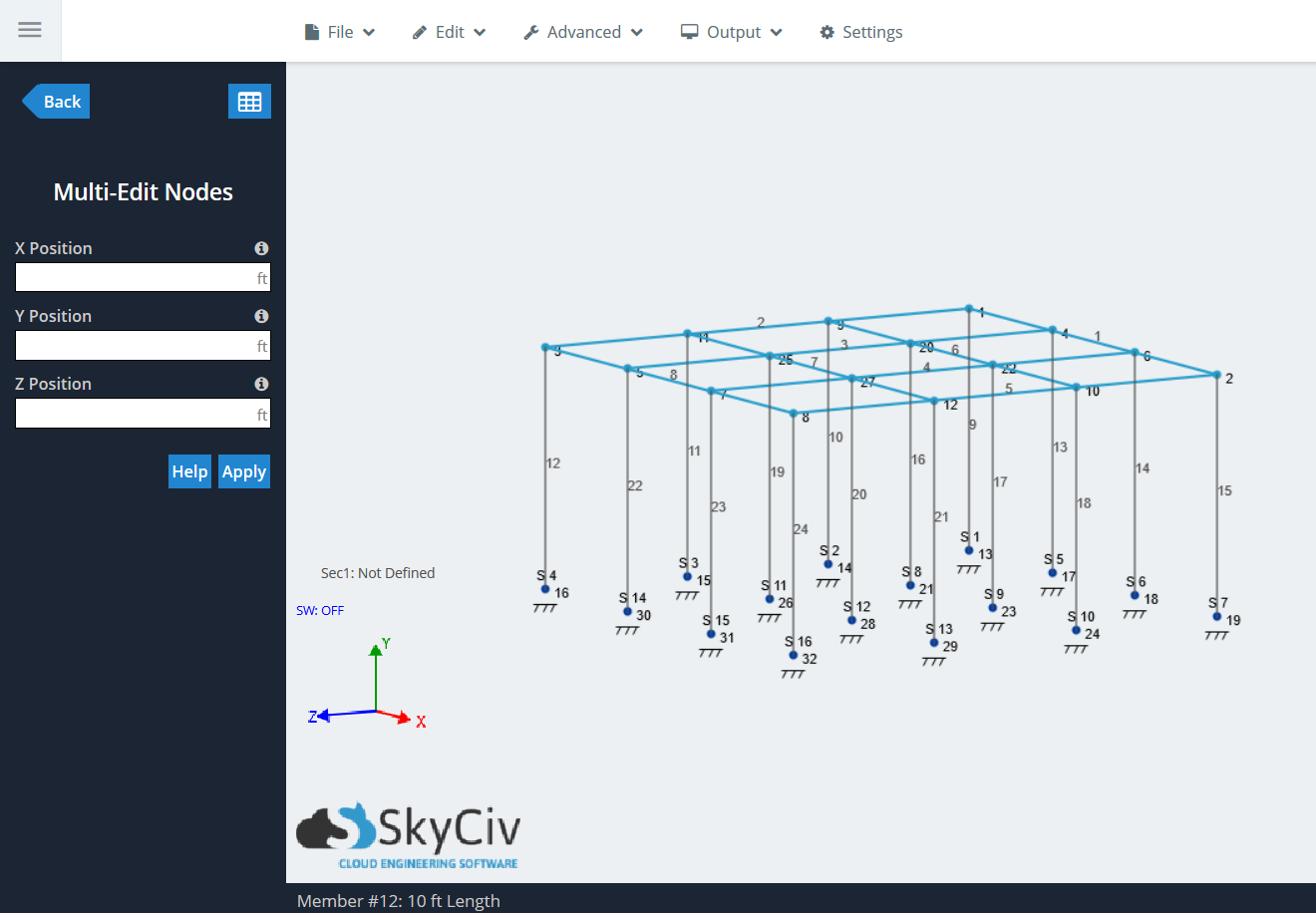
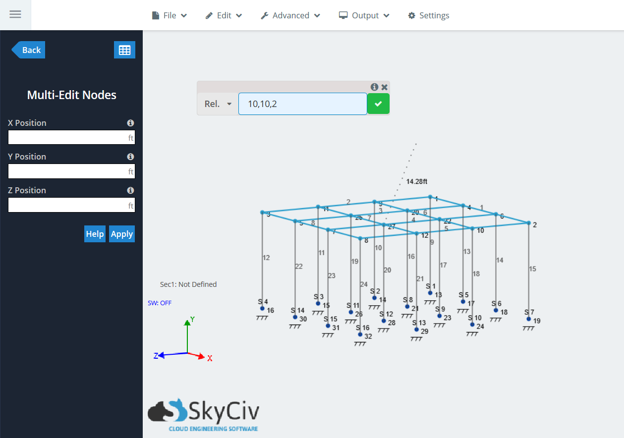
Now, create Relative Members using the “Rel.” function. Press “R” to bring up the Relative Member function and type in (10,10,2) for our delta values. You will see that there is a projection line showing the member line in addition to the member length:
Click the green check mark to generate the members. You should see a member and node created for every node that was selected during the process.
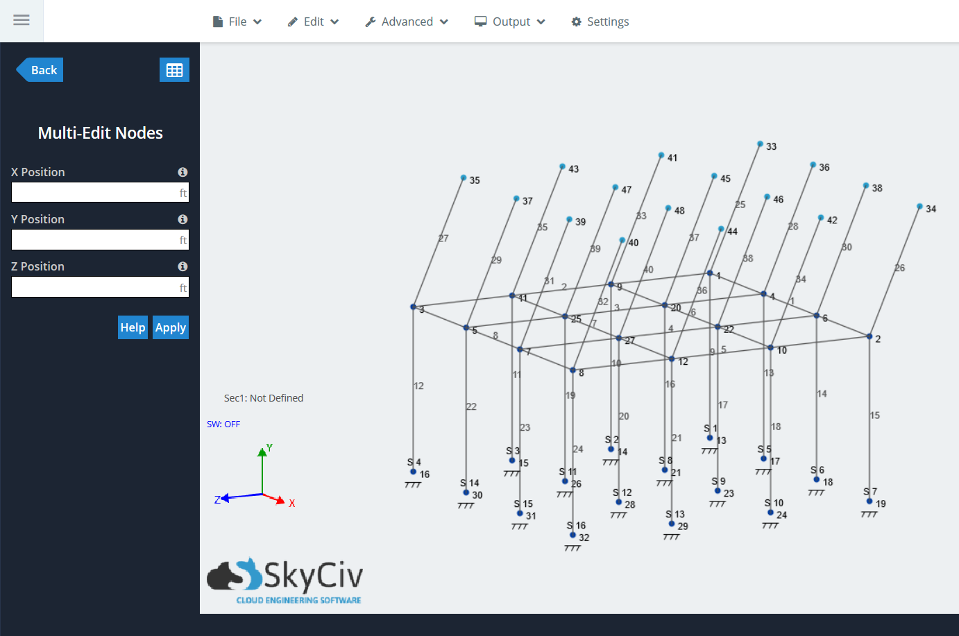
The ability to add multiple Relative Members at the same time opens the doors for nearly unlimited modelling possibilities for users. Try it out next you are modelling a project.
Shift while using Relative Member Function
The last useful functionality located within the Relative Member function is “Shift”, which is the last item in the dropdown menu. This is a quick and easy shortcut to use the same Shift Nodes function, located in Edit > Operations > Shift Nodes. A single or multiple nodes can be shifted around in 3D space, and will stay connected to members. Similar to the “Rel.” function, users must input the projection distances for each global axis’.
Example:
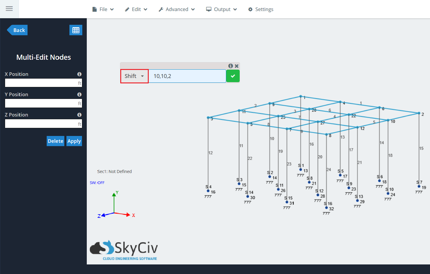
Using the same elevated platform in the last example, repeat the selection of the same elements on the “top floor” of the platform. Press “R” and find “Shift” in the dropdown. Type in the same values as before: (10,10,2). When using the Shift function, the projection line will not show because a new member is not being generated:
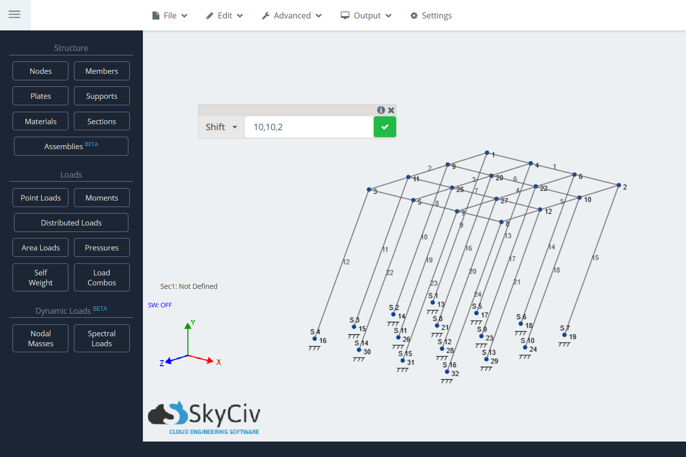
Click on the green check mark. All of the previous selected nodes will now move to the indicated location, moving the members as well:
Note: This can also be done with single nodes.


