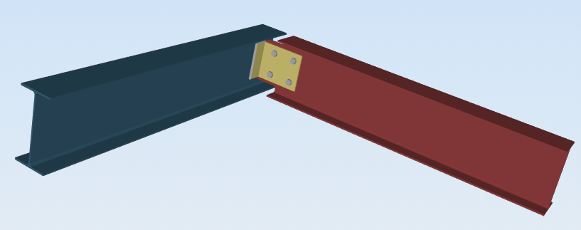
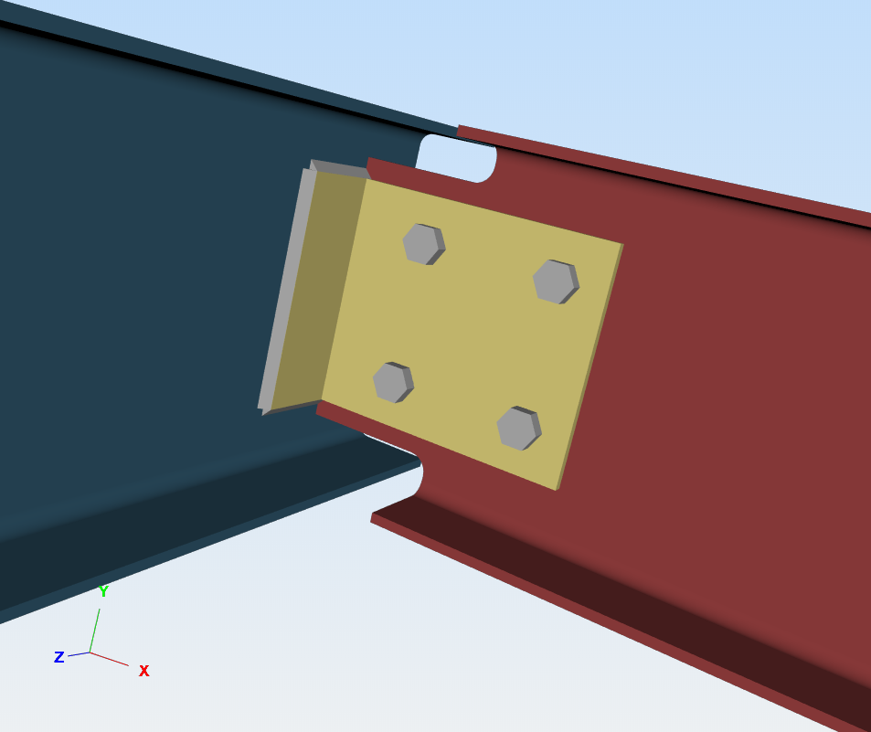
The child(ren) member(s) are the supported members of your connection assembly. Some connection assemblies support only 1 child member, whereas others support more than 1. The below example is of a HSS-to-W Collared Plate connection with 2 children (supported) members.
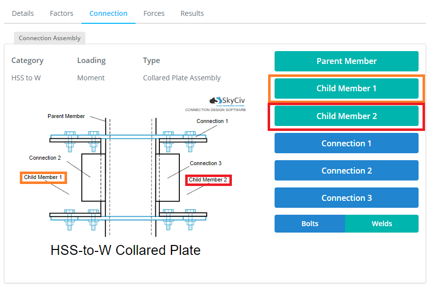
Integrated
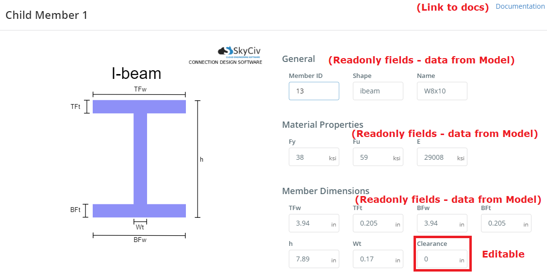
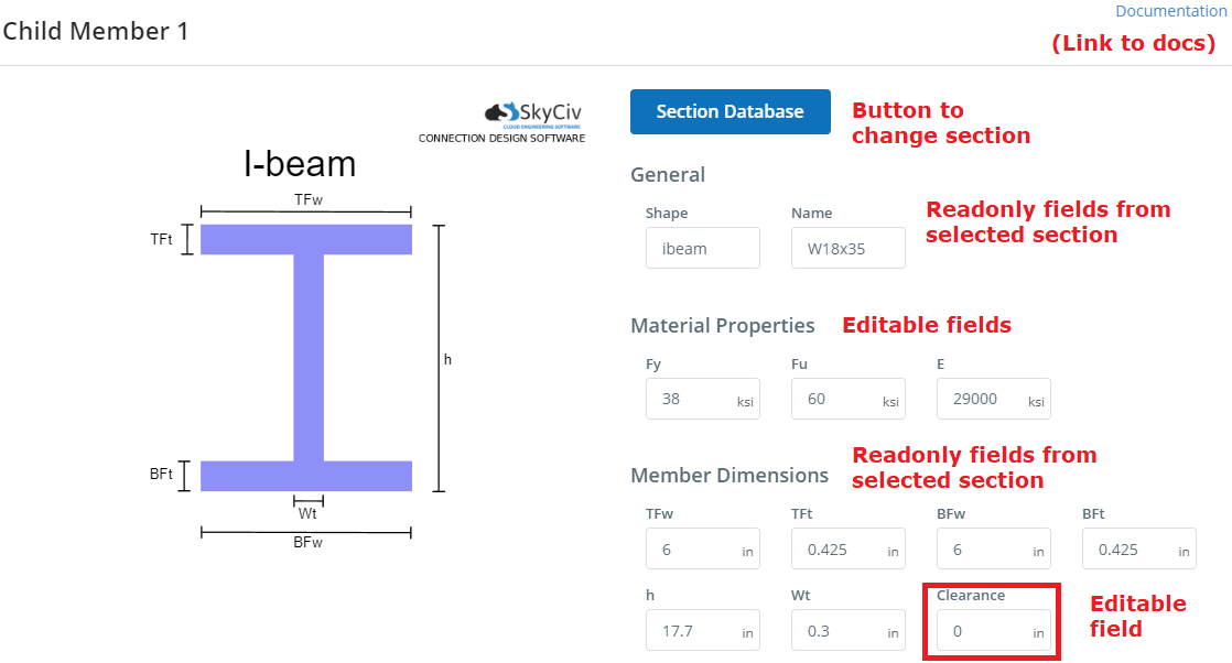
Similar to the parent member, when using connection design integrated with SkyCiv S3D, most options will not be directly editable. Instead, the section and material properties will be taken from the member that was chosen in the summary table. To change the values, you will need to change the section and/or material properties back in the Model. The main editable field is the clearance, which is the distance from the face of the child member to the connecting face of the parent member. By default, it will be 0.
Standalone
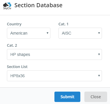
Just like the parent member options for the standalone version of Connection Design, you are able to change the cross section by adding one from our Section Database popup. Simply click the button to get started.
Coping Options
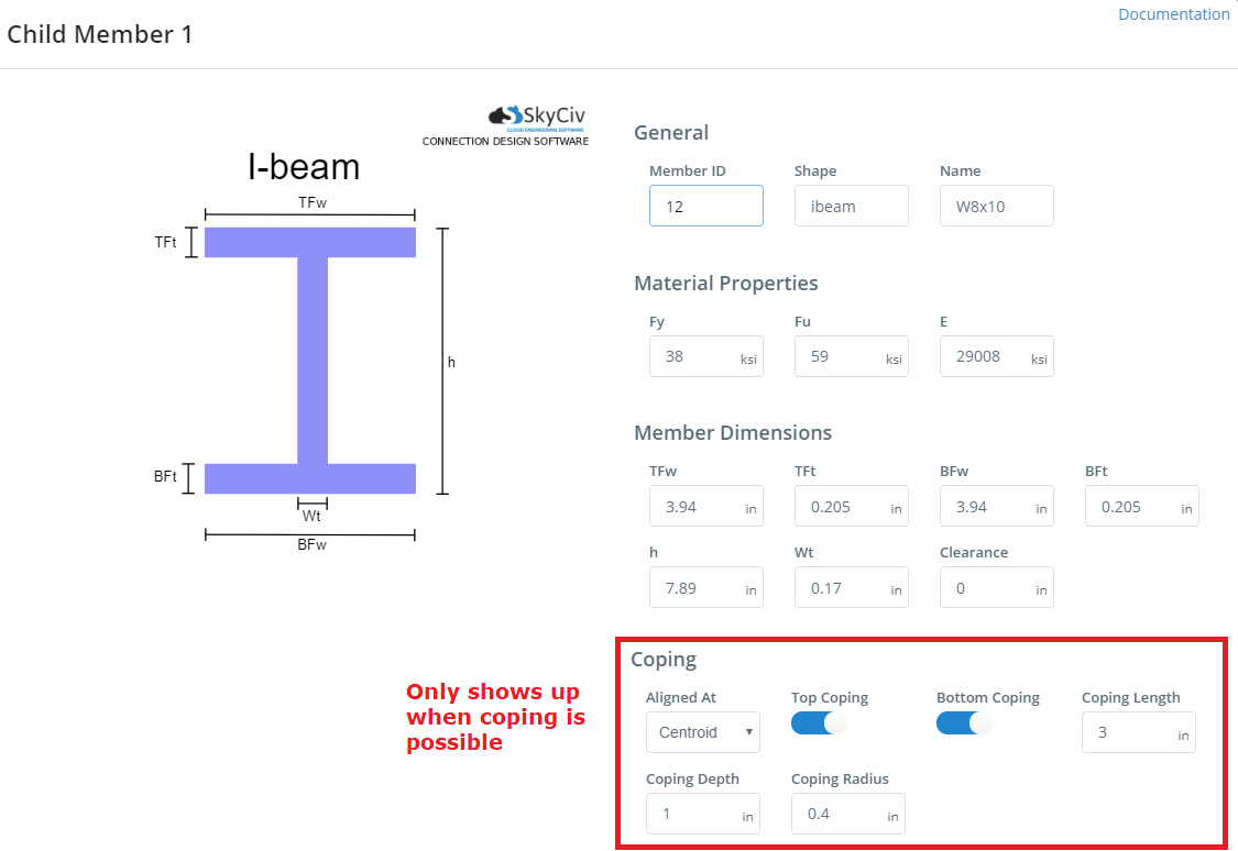
When coping is possible, that is when it is between W-to-W sections, in a beam to beam orientation, where the flanges are parallel and the webs are perpendicular, the coping options are available as shown below.
Coping Options
- Aligned At: Choose between ‘Centroid’, ‘Top Edge’, ‘Bottom Edge’. This is the alignment between the child member and the parent member.
- Top Coping: Toggle between off / on. If on, this implies that there is top coping to your child member.
- Bottom Coping: Just like the option for Top Coping, but for Bottom Coping.
- Coping Length: The coping length is the dimension along the longitudinal (local x) axis of the member.
- Coping Depth: The coping depth is the dimension along the local y axis of the member.
- Coping Radius The radius of the coping corner formed between the coping length and coping depth.
An example render of the coping options above are shown below.
