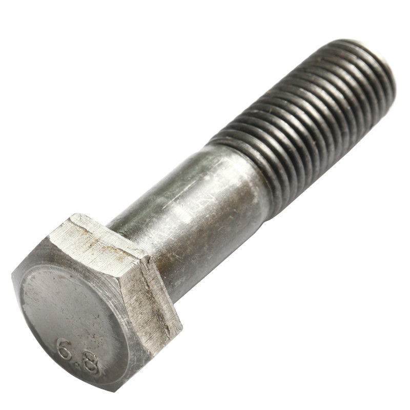
Structural steel members are connected to one another by means of filler elements or connectors which could be angle sections, plates or even parallel flange-channels (PFC). Those are some of the common configurations adopted on job sites, especially when bolts or bolted connections are primarily used. On the other hand, for welded connections, members are sometimes directly connected to each other without any filler elements or intermediate connectors. In this article, we will focus on bolts (hexagonal head and countersunk) and some of the common bolted connections used.
Hexagonal and Countersunk Bolts

American Institute of Steel Construction (AISC)
AISC primarily uses English units (i.e., inch, lbs) although the SI counterpart is also supported and available. One thing to take note of is that the dimensions in the English system are usually in increments of a quarter of an inch (⅛”) which may not exactly match those in the SI.
Bolt Diameter Comparison
| ½” | – |
| ⅝” | M16 |
| ¾” | M20 |
| ⅞” | M22 |
| 1” | M24 |
| 1 ⅛” | M27 |
| 1 ¼” | M30 |
| 1 ⅜” | – |
| 1 ½” | M36 |
High-Strength Bolts
Specifications for bolt materials are covered in the American Society for Testing and Materials (ASTM) which are mainly categorized into two groups – Group A and B:
Group A — ASTM A325, A325M, F1852, A354 Grade BC, and A449
Group B — ASTM A490, A490M, F2280, and A354 Grade BD
Besides differences and strengths and other properties, these groups have different requirements for minimum pretension depending on their diameters.
Eurocode 3 (UK National Annex)
The Eurocode is entirely in the SI units and as such, bolts are designated in millimeters (mm) with size prefixed with “M”, e.g. M16 meaning 16mm diameter bolt.
| M12 |
| M16 |
| M20 |
| M24 |
| M30 |
Bolt Classes – Tensile Strengths
Eurocode bolts are classified based on their approximate tensile strengths, for example, Class 4.6 would mean 4 x 6 x 10 = 240 MPa while Class 8.8 approximately has 640 MPa as its tensile strength and so on. However, in calculating actual bolt resistances, actual capacities are affected by the “preload” (or pretension in terms of AISC) tension which in certain cases, may increase the bolt carrying capacity if the right amount of tension is applied.
| 4.6 | M5 – M36 |
| 4.8 | M1.6 – M16 |
| 5.8 | M5 – M24 |
| 8.8 | M1.6 – M36 |
| 9.8 | M1.6 – M16 |
| 10 | 9 M5 – M36 |
| 12 | 9 M1.6 – M36 |
Notes on Hexagonal and Countersunk Bolts
The differences in geometry of hexagonal and countersunk bolts have effects mainly on the bearing capacity which may be evident due to such differences. (see figure below from AISC Manual 14th edn, Fig. 7-10)
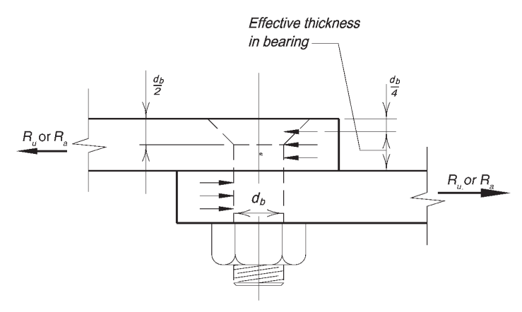
Figure 1. Effective Thickness in Bearing of a Countersunk Bolt
Connection Specifications and Bolt Holes
Bolted connections can be specified as snug-tightened, pretensioned or slip-critical. These conditions play a large role in consideration of the type of bolt holes used in the connection. These types are denoted as standard (normal, for EN), oversized or slotted (short or long) and they are adopted based on the connection specifications. For example, RCSC specifications outline the requirements for snug-tight conditions. However, if the connection is designed for certain conditions besides snug-tight, such condition must be clearly identified in the drawings (i.e. AISC pre-tension or EN pre-loading requirements).
Furthermore, slip-critical connections are important in designing against bearing in which slips must be prevented. Consequently, different factors are applied in the calculation of slip resistance based on the hole types as well. In most cases however, standard (normal) bolt holes are adopted in conjunction with a specific level of pretension (pre-load).
")
Figure 2. Bolted Angle – a type of shear connection
Bolted Connections
Bolted connections, in general, can be used in both shear plate connectors such as web plates, tees, web and seat angles and in moment connections (rigid, fully-restrained) which commonly use filler, continuity and splice plates. The use of bolts necessitates the addition of an intermediate connector or connecting element such as those mentioned.
")
Figure 3. Bolted Flange Plate Connection
In theory, there are many ways to set up a combination of connection configurations. However, due to practical reasons, i.e. buildability and fabrication, certain connection types are more favored than others and thus more widely adopted. Here are some of the common connection types which involve bolts together with their brief descriptions:
Shear (Simple) Connections
- Single/Double Plate (Tab or Fin) – uses plate(s) to connect a beam web with the supporting member (girder or column); one side usually requires a weld at the edge of the plate while the bolts are used to connect (in lap) to the beam web
- Single/Double Angle – similar to plates, angles may be connected in the same manner although it is possible to use bolts entirely on both sides of the connection
- Seat Angle – as the name suggests, an angle section is used to bear the flanges (or flats/walls for closed sections) of supported members (e.g. beam flanges) where it could “sit”. Bolts may be entirely used in this connection type
Moment (Restrained) Connections
- Flange Plates – in conjunction with a specified shear connection, flange plates are employed to provide continuity to flanges framed to columns of moment-resisting frames or more generally in member splices.
- Collar and Through Plates – this connection type is found in HSS (RHS or CHS) columns which form part of a moment-resisting frame system. The main difference is that through plates cut “through” the column while collar plates are inserted, much like “worn” by the column like a collar on a shirt. Both are expensive types of connection to fabricate due to the intricacies of the connection.
Visit our article on Types of Steel Connections to learn more or try our bolt shear strength calculator.
References:
[1] American Institute of Steel Construction (AISC). (2016). Specification for Structural Steel Buildings. Chicago, IL 60601-6204
[2] American Institute of Steel Construction (AISC). (2011). Steel Construction Manual. 14th Ed. Chicago, IL 60601-6204
[3] The Steel Construction Institute and The British Constructional Steelwork Association. (2014). Joints in Steel Construction Simple Joints to Eurocode 3. Ascot SL5 7QN; London SW1A 2ES, UK
[4] The Steel Construction Institute and The British Constructional Steelwork Association. (2014). Joints in Steel Construction Moment-Resisting Joints to Eurocode 3. Ascot SL5 7QN; London SW1A 2ES, UK