Bolt Shear Strength Calculator
The SkyCiv Bolt Shear Strength Calculator helps structural engineers calculate individual bolt forces and capacities for combined shear and tension loads. The bolt shear capacity quick design performs a comprehensive check of loads in any axis/direction in order to resolve bending moments, shear forces and axial forces into equivalent in-plane and out-of-plane forces on the bolt group. This Quick Design tool can check the bolt group for the following modes of failure:
- Bolt Shear Capacity
- Bolt Tension Capacity
- Combined Tension and Shear Capacity
- Bearing and Tearout Capacity
- Bolt Setout Requirements
The tool also allows for both elastic and plastic analysis and can assess the utilization of the bolt group in accordance with the following design standards:
- Australian Standards - AS 4100:2020
- United States - AISC 360-22 & AISC 360-16
- European Standards - EN 1993-1-8:2005
- New Zealand Standards - NZS 3404:1997
- Canadian Standards - CSA S16-24
The calculation results have been independently verified against the Australian Guidebook for Structural Engineers and Joints in Steel Construction: Moment-Resisting Joints to Eurocode 3.
About the Bolt Shear Strength Calculator
How to Use the Calculator?
Watch the video below for a walkthrough of the calculator, and visit our YouTube playlist for more engineering theory explanations and bolt design demos for EN 1993-1-8, AS 4100, and AISC 360-16.
What is Bolt Shear Strength?
Bolt shear strength is the capacity of a bolt to resist forces that attempt to cause the bolt to slide along a plane perpendicular to its axis. Most bolted connections rely on a bolts shear capacity in order to provide stability in the connection. For example, bolted splice connections are almost exclusively subject to shear forces. The SkyCiv Bolt Shear Strength Calculator is designed to assist in the calculation of individual bolt forces and capacities for combined shear and tension loads.
How Do Individual Bolts Resist Forces?
Bolts are individually capable of resisting tension and shear forces. Although theoretically bolts could also take moments and compression forces, bolts have a small section modulus that means moment resistance is relatively small and connection details often have compression forces resolved through plate-to-plate contact.
Most design standards in the world only describe the capacity of a bolt in tension and shear since bolts are only expected to take these types of loads.
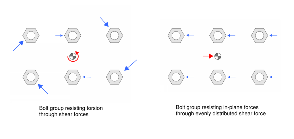
How Are Shear Forces Distributed Between Bolts?
In-plane forces are resolved in the bolt group through shear. The bolt group is modelled to evenly distribute direct in-plane forces and take torsion forces proportional to the distance from the bolts instantaneous point of rotation (ICR) which can generally be taken as the centroid. Therefore, the bolts with the highest shear forces are always bolts furthest from the ICR.
The design bolt shear force can be calculated by finding the bolt shear force in each of the in-plane directions and then combining them into a resultant shear force. The bolt shear capacity for a single bolt can then be compared to the critical bolt shear that develops for a single bolt within the group.
Bolt Shear Strength Formula
Bolt shear strength can generally be calculated with the following general formula:
Vf = 0.6 * fuf * A
where:
- fuf is the minimum tensile strength of the bolt
- A is the cross sectional area being intersected for a bolt
Bolt Shear Strength Formula for AS 4100:2020
The AS 4100 more specifically calculates bolt shear strength with the following equation:
ϕVf = ϕ * 0.62 * fuf * kr * krd * (nn * Ac + nx * Ao)
where:
- ϕ = 0.8
- fuf is the minimum tensile strength of the bolt
- kr is a reduction factor for bolted lap connections
- krd is a reduction factor to account for reduced ductility of grade 10.9 bolts
- nn is the number of shear planes with threads intercepting the shear plane
- Ac is the cross sectional area of bolts through its threads (known as core, minor or root area of bolt)
- nx is the number of shear planes without threads intercepting the shear plan
- Ao is the nominal plain shank area of the bolt
Example Bolt Shear Strength Calculation for AS 4100:2020
For a grade 4.6 M12 bolt with a minimum tensile strength of 400 MPa with 1 shear plane intersecting the shank of the bolt we can calculate the shear capacity as:
ϕVf = 0.8 * 0.62 * 400 MPa * 1 * 1* ( 0 * Ac + 1 * 113 mm2) = 22.4 kN
Bolt Shear Strength Formula for EN 1993-1-8:2005
The EN 1993-1-8:2005 (EC3) calculates the bolt shear capacity as:
Fv,Rd = αv * fub * A * βlf / γM2
where:
- αv = 0.6 for grade 4.6, 5.6 and 8.8 bolts and 0.5 otherwise
- fub is the bolt ultimate tensile strength
- A is the cross sectional area of the bolt
- A = As (tensile area of bolt) if the shear plane passes through the bolt threads
- A = Ag (gross cross sectional area of bolt) if the shear plane does not pass through the bolt threads
- βlf reduction factor for bolted lap connections
- γM2 = 1.25
Example Bolt Shear Strength Calculation for EN 1993-1-8:2005
For a grade 4.6 M12 bolt with a minimum tensile strength of 400 MPa with 1 shear plane intersecting the shank of the bolt we can calculate the shear capacity as:
ϕVf = 0.6 * 400 MPa * 113 mm2 * 1 / 1.25 = 21.7 kN
Available Bolt Shear Strength Formula for AISC 360-16
The AISC 360-16 calculates the available bolt shear capacity for allowable strength design (ASD) as:
Rn / Ω = Fnv * Ab / Ω
and calculates the available bolt shear capacity for load and resistance factor design (LRFD) as:
ϕ * Rn = ϕ * Fnv * Ab
where:
- ϕ = 0.75 for LRFD design
- Ω = 2 for ASD design method
- Fnv is the nominal shear strength from Table J3.2, typically:
- If shear plane includes threads (N) then Fnv= 0.450 * Fu
- If shear plane excludes threads (X) then Fnv= 0.563 * Fu
- where Fu is the bolt ultimate tensile strength
- Ab is the gross cross sectional area of the bolt
Example Bolt Shear Strength Calculation for AISC 360-16
For a Group A (Fu = 120 ksi) 1" diameter bolt with 1 shear plane intersecting the shank of the bolt (X) we can calculate the shear capacity as:
ϕ * Rn = 0.75 * 0.563 * 120 * 1^2 * π / 4 = 39.8 kip
Rn / Ω = 0.563 * 120 * 1^2 * π / 4 / 2 = 26.5 kip
Bolt Shear Strength Chart
Users can create there own bolt shear strength charts using the SkyCiv QD Bolt Group Capacity Calculator for different standards globally.
A user can specify inputs in the QD to match project requirements and generate a set of common capacities that can be used as a reference for projects. For example by using three runs of the AS 4100:2020 Bolt Group Capacity a simple table can start to be constructed.
| Size | Grade | Shear Plane | ϕVf |
|---|---|---|---|
| M16 | 8.8 | Thread Included (N) | 59.3 |
| M20 | 8.8 | Thread Included (N) | 92.7 |
| M24 | 8.8 | Thread Included (N) | 133.5 |
How to Calculate Bolt Yield Strength?
Bolt yield strength can generally be calculated with the following equation:
Ntf = As * fuf
where:
- A is the tensile stress area of the bolt
- fy is the minimum yield strength of the bolt
Bolt Tension Strength
Bolt tension strength refers to a bolts ability to resist pulling or tensile forces along its axis. This strength is particularly critical when a bolt group is required to resist moments since moments are generally resolved by a bolt taking tension forces at some lever arm distance away from the point of rotation. Although we could conservatively use the bolt yield strength in the tension strength design most standards around the world use the bolt's ultimate strength when considering the tensile strength of a bolt.
Bolt Tension Strength Formula
Bolt shear strength can generally be calculated with the following general equation:
Ntf = As * fuf
where:
- A is the tensile stress area of the bolt
- fuf is the minimum tensile strength of the bolt
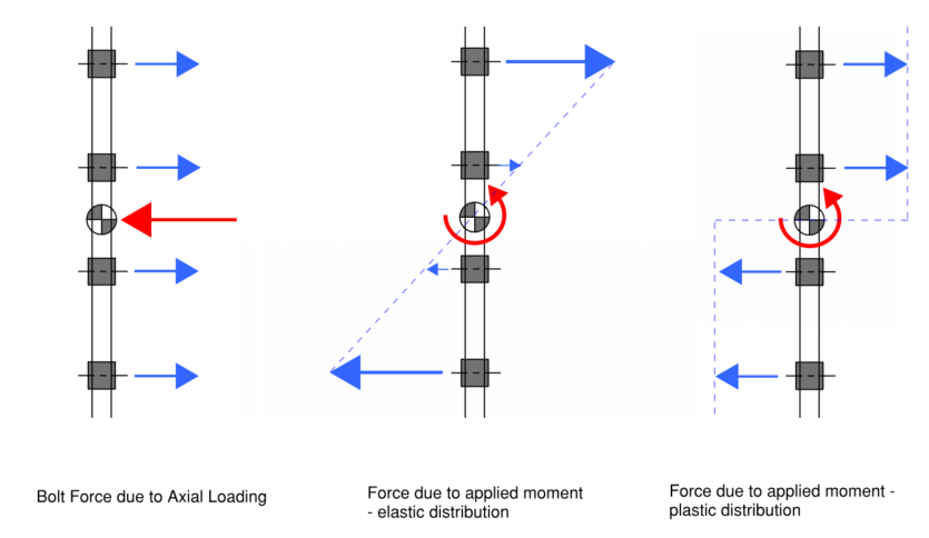
How Are Tensile Loads Distributed Between Bolts?
Forces due to axial loads are considered to be uniformly distributed across all bolts.
Forces due to applied moments are distributed based on either plastic or elastic analysis.
Tension or compression forces may develop in bolts, however since compression forces in reality are expected to be resolved by plate-to-plate contact only the critical tension force is adopted for design checks.
The maximum bolt tension can be found be combining the bolt tension forces that develop through axial loading and moments. The bolt tension capacity for a single bolt can then be compared to the critical bolt tension that develops for a single bolt within the group.
A bolt group can better resist forces than individual bolts since moments can be resolved by having bolts take tension (or compression) forces at some lever arm distance. This utilises the bolts capacity in tension to resolve moments in order to compensate for its small section modulus.
For example a single M12 bolt with a yield strength of 240 MPa and a tensile strength of 400 MPa would have a 0.04 kN.m moment capacity. However, the bolt has a tension capacity of 27 kN (for AS 4100:2020) and if we couple two M12 bolts together at a spacing of 100 mm we can resolve a 2.7 kN.m moment. This gives a moment capacity 30x larger than if we just used the moment capacity of the individual sections.
Bolt Tension Strength Formula for AS 4100:2020
The AS 4100 calculates bolt tensile strength as:
ϕNtf = ϕ * As * fuf
where:
- ϕ = 0.8
- As is the tensile stress area of the bolt (from AS 1275)
- fuf is the minimum tensile strength of the bolt
Example Bolt Tension Strength Calculation to AS 4100:2020
For a grade 4.6 M12 bolt with a minimum tensile strength of 400 MPa we can calculate the tensile capacity as:
ϕNtf = 0.8 * 84.3 mm2 * 400 MPa = 27 kN
Bolt Tension Strength Formula for EN 1993-1-8:2005
The Eurocode 3 calculates the bolt tensile strength as:
Ft,Rd = k2 * fub * As * / γM2
where:
- k2 is 0.63 for countersunk bolts and 0.9 otherwise
- As is the tensile stress area of the bolt (from AS 1275)
- fub is the minimum tensile strength of the bolt
- γM2 = 1.25
Example Bolt Tension Strength Calculation to EN 1993-1-8:2005
For a grade 4.6 M12 bolt with a minimum tensile strength of 400 MPa we can calculate the tensile capacity as:
Ft,Rd = 0.9 * 84.3 mm2 * 400 MPa / 1.25 = 24.3 kN
Available Bolt Tension Strength Formula for AISC 360-16
The AISC 360-16 calculates the available bolt tension capacity for allowable strength design (ASD) as:
Rn / Ω = Fnt * Ab / Ω
and calculates the available bolt tension capacity for load and resistance factor design (LRFD) as:
ϕ * Rn = ϕ * Fnt * Ab
where:
- ϕ = 0.75 for LRFD design
- Ω = 2 for ASD design method
- Fnt is the nominal tensile strength from Table J3.2, typically:
- Fnt= 0.75 * Fu
- where Fu is the bolt ultimate tensile strength
- Ab is the gross cross sectional area of the bolt
Example Available Bolt Tension Strength Calculation to AISC 360-16
For a Group A (Fu = 120 ksi) 1" diameter bolt with 1 shear plane intersecting the shank of the bolt (X) we can calculate the tension capacity as:
ϕ * Rn = 0.75 * 0.75* 120 * 1^2 * π / 4 = 53 kip
Rn / Ω = 0.75* 120 * 1^2 * π / 4 / 2 = 35.3 kip
Bolt Tension Strength Chart
Similar to the bolt shear strength chart, a user can also use the SkyCiv QD Bolt Group Capacity Calculator to generate tension strength charts for a project. For example the following chart is constructed using three runs of the AS4100:2020 Bolt Group Capacity Calculator
| Size | Grade | Shear Plane | ϕNtf |
|---|---|---|---|
| M16 | 8.8 | Thread Included (N) | 104 |
| M20 | 8.8 | Thread Included (N) | 162.5 |
| M24 | 8.8 | Thread Included (N) | 234 |
Can Bolts Take Compression?
Models of bolt groups often allocate compression forces to bolts on the compression side of the connection.
Compression forces however, are generally expected to be resolved through plate-to-plate contact and connection details often mean that bolts will only be engaged in tension.
Therefore the bolt compression forces in modelling is an idealisation to simplify calculations, but if a bolt is actually required to take compression forces this is something that should be considered by the engineer.
Bolt compression forces can be found with the SkyCiv Bolt Group Capacity Calculator by reversing load directions and taking the tension force in the reversed model. An upper bound for the compression capacity can be found by using the tension capacity, however the compression capacity would need to account for the possibility of buckling.
What is Block Shear?
The block shear failure mechanism can develop on a plate due to bolt holes reducing the section capacity of the plate.
In general we have a reduced effective area for tension and shear capacity on the plate due to the bolt holes cut in the plate.
Typically standards required that the tension capacity of a plate is assessed by calculating the plate yield strength by multiplying the gross area of the plate by the yield strength of the steel. When there are bolt holes the tension rupture strength of the plates should also be assessed by multiplying the net area of the plate by the ultimate tensile strength of the steel plate. That is:
- Tensile yielding capacity = Fy * Ag
- Tensile rupture capacity = Fu * An
Similarly the plate shear capacity is calculated by taking the minimum of the gross area of the steel plate multiplied by 60% of the yield strength and the net area of the steel plate multiplied by 60% of the ultimate tension strength of the steel plate. That is:
- Shear yielding capacity = 0.6 * Fy * Ag
- Shear rupture capacity = 0.6 * Fu * An
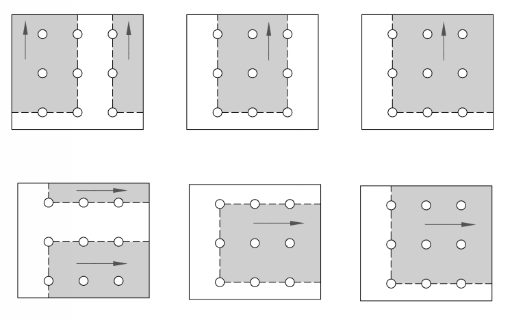
We also might have a combined failure of tension and shear on the plate which is referred to as block shear. All the bolt holes collectively rip out a section of the plate. Possible block shear failure mechanisms are shown in the image below.
How to Calculate Block Shear Capacity?
There are slight variations on how the capacity is calculated in standards around the world but they all are calculated through the same general approach of combining the capacity of the area failing in shear with the capacity of the area failing in tension.
Where tension stress on the section is non-uniform the tension capacity component of block shear is typically reduced by 50%.
The Eurocode calculates block tearing as:
- Veff,Rd = 0.577 * Fy * Anv / γM2 + Ubs * Fu * Ant / γM2
AISC 360-16 calculates block shear as:
- LRFD: ϕ Rn = ϕ (0.6 * Fu * Anv + Ubs * Fu * Ant) ≤ ϕ (0.6 Fy * Agv + Ubs * Fu * Ant)
- ASD: Rn / Ω = (0.6 * Fu * Anv + Ubs * Fu * Ant) / Ω ≤ (0.6 Fy * Agv + Ubs * Fu * Ant) / Ω
The Australian Standard calculates block shear as:
- ϕ Rbs = ϕ (0.6 * Fuc * Anv + kbs * Fuc * Ant) ≤ ϕ (0.6 Fyc * Agv + Ubs * Fu * Ant)
where:
- Agv = gross area subject to shear at rupture
- Anv = net area subject to shear at rupture
- Ant = net area subject to tension at rupture
- Fu & Fuc = minimum tensile strength of the steel plate
- Fy & Fyc = yield strength of the steel plate
- kbs & Ubs = a reduction factor for non-uniform tension
- 0.5 when tension stress is non-uniform
- 1.0 when tension stress is uniform
- γM0 = 1.0
- γM2 = 1.25
- ϕ = 0.75 for both AISC and AS
- Ω = 2.00
The Eurocode presents a simpler more conservative method for the calculation by using the net shear in combination with the yield stress.
What Area to use for Force on a Bolt?
The area to use when designing for a bolted connection depends on the type of force we are considering.
For tension forces on a bolt the entire bolt is stressed and the failure plane can develop at any point along the bolt. As a result the critical failure plane is the cross-section with the smallest area in the direction perpendicular to the axis of the bolt. For a standard bolt this area passes through the threaded section of the bolt and as a result is a smaller area than the gross cross-sectional area of the bolt.
This area is called the “Tensile Stress Area” and is dependent on the bolt size and pitch. Generally this value can be found in tables or it can be calculated using the tensile diameter of the bolt.
When considering shear forces on a bolt the area we use depends on if the shear plane is intersecting the shank of the bolt or the threaded portion of the bolt. If the shear plane intersects the bolt shank the area is simply taken as the gross cross-sectional area for the bolt size.
For calculations to the AISC 360-16 the gross-cross sectional area is always used since the reduction in area is taken into consideration by the nominal strength values for the bolt as shown in Table J3.2.
Bolt Cross Section Calculation Example (metric)
To calculate the bolt cross-sectional area for tension strength calculations we first calculate the bolt tensile diameter Dt as:
Dt = D0 - 0.938194 * p
For example for a M24 bolt with a 3 mm pitch
Dt = 24 - 0.938194 * 3 = 21.19 mm
We can then calculate the area of the bolt using the formula for the area of a circle as:
3.14 * 21.192 / 4 = 352.5 mm2
To calculate the bolt cross-sectional area for shear failure along the shank of the bolt we can simply use the bolt nominal diameter. For example for a 24 mm bolt we take the area as
3.14 * 242 / 4 = 452.1
To calculate the bolt cross-sectional area for shear failure through the threaded portion of the bolt the Eurocode 3 simply uses the tension stress area of the bolt. The Australian standard however has a separate calculation which is to calculate the core diameter (also known as minor diameter or root diameter) of the bolt. We can calculate this through the formula:
Dc = D0 - 1.226869 * p
For example for a M24 bolt
Dc = 24 - 1.226869 * 3 = 20.319 mm
Ac = 3.14 * 20.3192 / 4 = 324 mm2
Bolt Cross Section Table (metric)
A summary of the cross-sectional areas used for metric bolts strength calculations in the Eurocode 3 and the Australian standards is shown in the table below
| Size | Pitch | Dt | Dc | A0 | As | Ac |
|---|---|---|---|---|---|---|
| 4 | 0.7 | 3.34 | 3.14 | 12.6 | 8.7 | 7.7 |
| 6 | 1 | 5.06 | 4.77 | 28.3 | 20.1 | 17.8 |
| 8 | 1.25 | 6.83 | 6.47 | 50.3 | 36.6 | 32.8 |
| 10 | 1.5 | 8.59 | 8.16 | 78.5 | 57.9 | 52.2 |
| 12 | 1.75 | 10.36 | 9.85 | 113.1 | 84.2 | 76.2 |
| 16 | 2 | 14.12 | 13.55 | 201.1 | 156.6 | 144.1 |
| 20 | 2.5 | 17.65 | 16.93 | 314.2 | 244.7 | 225.1 |
| 24 | 3 | 21.19 | 20.32 | 452.4 | 352.5 | 324.2 |
| 30 | 3.5 | 26.72 | 25.71 | 706.9 | 560.5 | 518.9 |
| 36 | 4 | 32.25 | 31.09 | 1017.9 | 816.7 | 759.2 |
| 42 | 4.5 | 37.78 | 36.48 | 1385.4 | 1120.9 | 1045.1 |
| 48 | 5 | 43.31 | 41.87 | 1809.6 | 1473.1 | 1376.5 |
| 56 | 5.5 | 50.84 | 49.25 | 2463 | 2030 | 1905.2 |
| 64 | 6 | 58.73 | 56.64 | 3217 | 2675.9 | 2519.5 |
Bolt Cross Section Calculation Example (imperial)
The concepts behind which area to use for a bolt remain the same as for the metric system however the way that the AISC 360-16 handles this reduction in area is by instead reducing the nominal stress that the bolt can resist.
For calculations to the AISC 360-16 we always use the gross-cross sectional area of the bolt however we have the following reductions on the nominal tension and shear strength of the bolt. These values are calculated for us in table J3.2 and the way these values are calculated are as follows:
For tension
Fnt = 0.75 * Fu
For shear when threads are excluded from the shear planes
Fnt = 0.563 * Fu
For shear when threads are not excluded from the shear planes:
Fnt = 0.45 * Fu
The 0.75 factor accounts for the reduced area in the threaded portion of the bolt compared to the gross-cross sectional area.
The 0.563 number is derived from combining the shear/tension strength ratio of 0.625 combined with a 0.9 length reduction factor. The factor of 0.45 is then calculated as 80% of 0.563 so we can also consider this as suggesting that the shear area when intersecting the thread is simplified to be 80% of the gross-cross sectional area.
Based on the above interpretation of the AISC 360-16 we can calculate that for a 1” bolt we have a gross cross sectional area of Ab = pi * 1^2 / 4 = 0.7854 in2.
The tension stress area is calculated as:
A = 0.75 * Ab = 0.5890 in2
The shear stress area when threads are excluded from the shear plane can be calculated as:
A = Ab
The shear stress area when threads are not excluded from the shear plane can be calculated as:
A = 0.8 * Ab = 0.6283 in2
In practice these areas are not used and we just use the gross cross-sectional area of the bolt taken from table J3.2 of the AISC 360-16
AS 4100:2020 Bolt Group Capacity Design Software
The Bolt Group Capacity Calcualtor above also supports the design of bolt groups as per AS 4100:2020 Section 9 and New Zealand Standard 3404:1997 Section 9. You can change versions at the top of the input panel or by visiting the SkyCiv Quick Design Library.
General Design Notes AS 4100 Bolt Group Design
- Elastic distribution determines shear and tension forces in each bolt. This governs bolt demand only; capacities are determined from the limit state provisions.
- Bolt tensile stress area, shank area, and core area are taken from AS 1275.
- Prying action is incorporated by amplifying bolt tension using a user defined prying factor.
- The shear plane type (thread or shank) affects available shear capacity in accordance with AS 4100:2020 Clause 9.2.2.1.
- Tension capacity is calculated in accordance with AS 4100:2020 Clause 9.2.2.2.
- Combined shear and tension checks is calculated in accordance with AS 4100:2020 Clause 9.2.2.3.
- Ply in bearing is evaluated in accordance with AS 4100:2020 Clause 9.2.2.4.
- All bolts in the group are assumed identical and located within a single shear plane.
- Geometric properties such as centroid and second moment of area are calculated from bolt coordinates.
- Design capacities include capacity factors from AS 4100:2020 Table 3.4.
- This module currently supports metric units only.
AS 4100:2020 Table 9.2.1 - Bolts and Bolting Category.
| Bolting Category | Bolt Standard | Bolt Grade | Method of Tensioning | Min. Tensile Strength (MPa) |
|---|---|---|---|---|
| 4.6/S | AS 1111 (series), AS 1110 (series) | 4.6 | Snug tight | 400 |
| 8.8/S | AS/NZS 1252.1, AS 1110 (series) | 8.8 | Snug tight | 830 |
| 8.8/TB | AS/NZS 1252.1 | 8.8 | Full tensioning | 830 |
| 8.8/TF | AS/NZS 1252.1 | 8.8 | Full tensioning | 830 |
| 10.9/S | AS/NZS 1252.1 | 10.9 | Snug tight | 1040 |
| 10.9/TB | AS/NZS 1252.1 | 10.9 | Full tensioning | 1040 |
| 10.9/TF | AS/NZS 1252.1 | 10.9 | Full tensioning | 1040 |
- fuf is the minimum tensile strength of the bolt as specified in AS 4291.1:2015.
- Bolt grades 4.6, 8.8 and 10.9 are provided for simplified selection.
- Custom bolt grades with user defined fuf values are also supported.
SkyCiv Design Software
SkyCiv offers a wide range of Cloud Structural Analysis and Engineering Design Software, including:
- SkyCiv Quick Design Module
- Steel Design Capacity Software
- Cold Formed Steel Design Software
- Weld Group Capacity Software
- Eccentrically Loaded Bolt Group Software
- Purlin Span Calculator
- Rebar Development Length Calculator
- Aluminium Design Software
- Concrete Column Design Software
- AS 2870 Residential Slab on Grade Design
- Scaffolding Design Software
As a constantly evolving tech company, we're committed to innovating and challenging existing workflows to save engineers time in their work processes and designs.
