Base Plate Design Example using EN 1993-1-8:2005, EN 1993-1-1:2005, EN 1992-1-1:2004, and EN 1992-4:2018.
Problem Statement
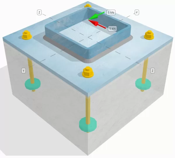
Determine whether the designed column-to-base plate connection is sufficient for a Vy=5-kN and Vz=5-kN shear loads.
Given Data
Column:
Column section: SHS 180x180x8
Column area: 5440 mm2
Column material: S235
Base Plate:
Base plate dimensions: 350 mm x 350 mm
Base plate thickness: 12 mm
Base plate material: S235
Grout:
Grout thickness: 6 mm
Grout material: ≥ 30 MPa
Concrete:
Concrete dimensions: 350 mm x 350 mm
Concrete thickness: 350 mm
Concrete material: C25/30
Cracked or Uncracked: Cracked
Anchors:
Anchor diameter: 12 mm
Effective embedment length: 150 mm
Embedded plate diameter: 60 mm
Embedded plate thickness: 10 mm
Anchor material: 8.8
Other information:
- Non-countersunk anchors.
- Anchor with cut threads.
- K7 factor for anchor steel shear failure: 1.0
- Degree of Restraint of Fastener: No restraint
Welds:
Weld type: Fillet Weld
Weld leg size: 8mm
Filler metal classification: E35
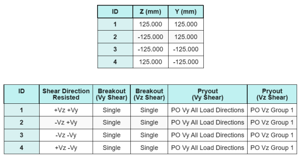
Anchor Data (from SkyCiv Calculator):
Model in SkyCiv Free Tool
Model the base plate design above using our free online tool today! No sign-up required.
Definitions
Load Path:
The SkyCiv Base Plate Design Software follows EN 1992-4:2018 for anchor rod design. Shear loads applied to the column are transferred to the base plate through the welds and then to the supporting concrete through the anchor rods. Friction and shear lugs are not considered in this example, as these mechanisms are not supported in the current software.
Anchor Groups:
The software includes an intuitive feature that identifies which anchors are part of an anchor group for evaluating concrete shear breakout and concrete shear pryout failures.
An anchor group is defined as two or more anchors with overlapping projected resistance areas. In this case, the anchors act together, and their combined resistance is checked against the applied load on the group.
A single anchor is defined as an anchor whose projected resistance area does not overlap with any other. In this case, the anchor acts alone, and the applied shear force on that anchor is checked directly against its individual resistance.
This distinction allows the software to capture both group behavior and individual anchor performance when assessing shear-related failure modes.
Step-by-Step Calculations
Check #1: Calculate weld capacity
We assume that the Vz shear load is resisted by the top and bottom welds, while the Vy shear load is resisted exclusively by the left and right welds.
To determine the weld capacity of the top and bottom welds, we first calculate their total weld lengths.
\(
L_{w,top\&bottom} = 2 \left(b_{col} – 2t_{col} – 2r_{col}\right)
= 2 \times \left(180 \,\text{mm} – 2 \times 8 \,\text{mm} – 2 \times 4 \,\text{mm}\right)
= 312 \,\text{mm}
\)
Next, we calculate the stresses in the welds.
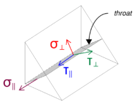
Note that the applied Vz shear acts parallel to the weld axis, with no other forces present. This means the perpendicular stresses can be taken as zero, and only the shear stress in the parallel direction needs to be calculated.
\(
\sigma_{\perp} = \frac{N}{(L_{w,top\&bottom})\,a\sqrt{2}}
= \frac{0 \,\text{kN}}{(312 \,\text{mm}) \times 5.657 \,\text{mm} \times \sqrt{2}}
= 0
\)
\(
\tau_{\perp} = \frac{0}{(L_{w,top\&bottom})\,a\sqrt{2}}
= \frac{0 \,\text{kN}}{(312 \,\text{mm}) \times 5.657 \,\text{mm} \times \sqrt{2}}
= 0
\)
\(
\tau_{\parallel} = \frac{V_{z}}{(L_{w,top\&bottom})\,a}
= \frac{5 \,\text{kN}}{(312 \,\text{mm}) \times 5.657 \,\text{mm}}
= 2.8329 \,\text{MPa}
\)
Using EN 1993-1-8:2005, Eq. 4.1, the design weld stress is obtained using the directional method.
\(
F_{w,Ed1} = \sqrt{ (\sigma_{\perp})^2 + 3 \left( (\tau_{\perp})^2 + (\tau_{\parallel})^2 \right) }
= \sqrt{ (0)^2 + 3 \times \left( (0)^2 + (2.8329 \,\text{MPa})^2 \right) }
= 4.9067 \,\text{MPa}
\)
In addition, the design normal stress for the base metal check, per EN 1993-1-8:2005, Eq. 4.1, is taken as zero, since no normal stress is present.
\(
F_{w,Ed2} = \sigma_{\perp} = 0
\)
Now, let us assess the left and right welds. As with the top and bottom welds, we first calculate the total weld length.
\(
L_{w,left\&right} = 2 \left(d_{col} – 2t_{col} – 2r_{col}\right)
= 2 \times \left(180 \,\text{mm} – 2 \times 8 \,\text{mm} – 2 \times 4 \,\text{mm}\right)
= 312 \,\text{mm}
\)
We then calculate the components of the weld stresses.
\(
\sigma_{\perp} = \frac{N}{(L_{w,left\&right})\,a\sqrt{2}}
= \frac{0 \,\text{kN}}{(312 \,\text{mm}) \times 5.657 \,\text{mm} \times \sqrt{2}}
= 0
\)
\(
\tau_{\perp} = \frac{0}{(L_{w,left\&right})\,a\sqrt{2}}
= \frac{0 \,\text{kN}}{(312 \,\text{mm}) \times 5.657 \,\text{mm} \times \sqrt{2}}
= 0
\)
\(
\tau_{\parallel} = \frac{V_y}{(L_{w,left\&right})\,a}
= \frac{5 \,\text{kN}}{(312 \,\text{mm}) \times 5.657 \,\text{mm}}
= 2.8329 \,\text{MPa}
\)
Using EN 1993-1-8:2005, Eq. 4.1, we determine both the design weld stress and the design normal stress for the base metal check.
\(
F_{w,Ed1} = \sqrt{ \left( \sigma_{\perp} \right)^2 + 3 \left( \left( \tau_{\perp} \right)^2 + \left( \tau_{\parallel} \right)^2 \right) }
\)
\(
F_{w,Ed1} = \sqrt{ \left( 0 \right)^2 + 3 \times \left( \left( 0 \right)^2 + \left( 2.8329 \,\text{MPa} \right)^2 \right) }
\)
\(
F_{w,Ed1} = 4.9067 \,\text{MPa}
\)
The next step is to identify the governing weld stress between the top/bottom welds and the left/right welds. Because the weld lengths are equal and the applied loads have the same magnitude, the resulting weld stresses are equal.
\(
F_{w,Ed1} = \max(F_{w,Ed1}, \, F_{w,Ed1})
= \max(4.9067 \,\text{MPa}, \, 4.9067 \,\text{MPa})
= 4.9067 \,\text{MPa}
\)
The base metal stress remains zero.
\(
F_{w,Ed2} = \max(F_{w,Ed2}, \, F_{w,Ed2}) = \max(0, \, 0) = 0
\)
Now, we calculate the weld capacity. First, the resistance of the fillet weld is computed. Then, the resistance of the base metal is determined. Using EN 1993-1-8:2005, Eq. 4.1, the capacities are calculated as follows:
\(
F_{w,Rd1} = \frac{f_u}{\beta_w \left(\gamma_{M2,weld}\right)}
= \frac{360 \,\text{MPa}}{0.8 \times (1.25)}
= 360 \,\text{MPa}
\)
\(
F_{w,Rd2} = \frac{0.9 f_u}{\gamma_{M2,weld}}
= \frac{0.9 \times 360 \,\text{MPa}}{1.25}
= 259.2 \,\text{MPa}
\)
Finally, we compare the weld stresses with the weld capacities, and the base metal stresses with the base metal capacities.
Since 4.9067 MPa < 360 MPa and 0 MPa < 259.2 MPa, the capacity of the welded connection is sufficient.
Check #2: Calculate concrete breakout capacity due to Vy shear
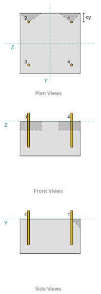
Following the provisions of EN 1992-4:2018, the edge perpendicular to the applied load is assessed for shear breakout failure. Only the anchors nearest to this edge are considered engaged, while the remaining anchors are assumed not to resist shear.
These edge anchors must have a concrete edge distance greater than the larger of 10·hef and 60·d, where hef is the embedment length and d is the anchor diameter. If this condition is not met, the thickness of the base plate must be less than 0.25·hef.
If the requirements in EN 1992-4:2018, Clause 7.2.2.5(1), are not satisfied, the SkyCiv software cannot proceed with the design checks, and the user is advised to refer to other relevant standards.
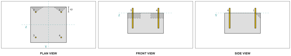
From the SkyCiv software results, the edge anchors act as single anchors, since their projected areas do not overlap. For this calculation, Anchor 1 will be considered.
To calculate the portion of the Vy shear load carried by Anchor 1, the total Vy shear is distributed among the anchors nearest to the edge. This gives the perpendicular force on Anchor 1.
\(
V_{\perp} = \frac{V_y}{n_{a,s}}
= \frac{5 \,\text{kN}}{2}
= 2.5 \,\text{kN}
\)
For the parallel force, it is assumed that all anchors resist the load equally. Therefore, the parallel component of the load is calculated as:
\(
V_{\parallel} = \frac{V_z}{n_{anc}}
= \frac{5 \,\text{kN}}{4}
= 1.25 \,\text{kN}
\)
The total shear load on Anchor 1 is therefore:
\(
V_{Ed} = \sqrt{ \left( V_{\perp} \right)^2 + \left( V_{\parallel} \right)^2 }
\)
\(
V_{Ed} = \sqrt{ \left( 2.5 \,\text{kN} \right)^2 + \left( 1.25 \,\text{kN} \right)^2 } = 2.7951 \,\text{kN}
\)
The first part of the capacity calculation is to determine the alpha and beta factors. We use EN 1992-4:2018, Clause 7.2.2.5, to set the lf dimension, and Equations 7.42 and 7.43 to determine the factors.
\(
l_f = \min(h_{ef}, \, 12d_{anc})
= \min(150 \,\text{mm}, \, 12 \times 12 \,\text{mm})
= 144 \,\text{mm}
\)
\(
\alpha = 0.1 \left(\frac{l_f}{c_{1,s1}}\right)^{0.5}
= 0.1 \times \left(\frac{144 \,\text{mm}}{50 \,\text{mm}}\right)^{0.5}
= 0.16971
\)
\(
\beta = 0.1 \left(\frac{d_{anc}}{c_{1,s1}}\right)^{0.2}
= 0.1 \times \left(\frac{12 \,\text{mm}}{50 \,\text{mm}}\right)^{0.2}
= 0.07517
\)
The next step is to calculate the initial value of the characteristic resistance of the fastener. Using EN 1992-4:2018, Equation 7.41, the value is:
\(
V^{0}_{Rk,c} = k_9 \left( \frac{d_{anc}}{\text{mm}} \right)^{\alpha}
\left( \frac{l_f}{\text{mm}} \right)^{\beta}
\sqrt{ \frac{f_{ck}}{\text{MPa}} }
\left( \frac{c_{1,s1}}{\text{mm}} \right)^{1.5} N
\)
\(
V^{0}_{Rk,c} = 1.7 \times \left( \frac{12 \,\text{mm}}{1 \,\text{mm}} \right)^{0.16971}
\times \left( \frac{144 \,\text{mm}}{1 \,\text{mm}} \right)^{0.07517}
\times \sqrt{ \frac{20 \,\text{MPa}}{1 \,\text{MPa}} }
\times \left( \frac{50 \,\text{mm}}{1 \,\text{mm}} \right)^{1.5}
\times 0.001 \,\text{kN}
\)
\(
V^{0}_{Rk,c} = 5.954 \,\text{kN}
\)
Then, we compute the reference projected area of a single anchor, following EN 1992-4:2018, Equation 7.44.
\(
A_{c,V}^{0} = 4.5 \left( c_{1,s1} \right)^2
= 4.5 \times \left( 50 \,\text{mm} \right)^2
= 11250 \,\text{mm}^2
\)
After that, we compute the actual projected area of Anchor 1.
\(
B_{c,V} = \min(c_{left,s1}, \, 1.5c_{1,s1}) + \min(c_{right,s1}, \, 1.5c_{1,s1})
\)
\(
B_{c,V} = \min(300 \,\text{mm}, \, 1.5 \times 50 \,\text{mm}) + \min(50 \,\text{mm}, \, 1.5 \times 50 \,\text{mm}) = 125 \,\text{mm}
\)
\(
H_{c,V} = \min(1.5c_{1,s1}, \, t_{conc}) = \min(1.5 \times 50 \,\text{mm}, \, 200 \,\text{mm}) = 75 \,\text{mm}
\)
\(
A_{c,V} = H_{c,V} B_{c,V} = 75 \,\text{mm} \times 125 \,\text{mm} = 9375 \,\text{mm}^2
\)
We also need to calculate the parameters for shear breakout. We use EN 1992-4:2018, Equation 7.4, to get the factor that accounts for the disturbance of stress distribution, Equation 7.46 for the factor that accounts for the member thickness, and Equation 7.48 for the factor that accounts for the influence of a shear load inclined to the edge. These are calculated as follows:
\(
\Psi_{s,V} = \min \left( 0.7 + 0.3 \left( \frac{c_{2,s1}}{1.5c_{1,s1}} \right), \, 1.0 \right)
= \min \left( 0.7 + 0.3 \times \left( \frac{50 \,\text{mm}}{1.5 \times 50 \,\text{mm}} \right), \, 1 \right)
= 0.9
\)
\(
\Psi_{h,V} = \max \left( \left( \frac{1.5c_{1,s1}}{t_{conc}} \right)^{0.5}, \, 1 \right)
= \max \left( \left( \frac{1.5 \times 50 \,\text{mm}}{200 \,\text{mm}} \right)^{0.5}, \, 1 \right)
= 1
\)
\(
\alpha_{V} = \tan^{-1} \left( \frac{V_{\parallel}}{V_{\perp}} \right)
= \tan^{-1} \left( \frac{1.25 \,\text{kN}}{2.5 \,\text{kN}} \right)
= 0.46365 \,\text{rad}
\)
\(
\Psi_{\alpha,V} = \max \left(
\sqrt{ \frac{1}{(\cos(\alpha_{V}))^2 + \left( 0.5 \, (\sin(\alpha_{V})) \right)^2 } }, \, 1 \right)
\)
\(
\Psi_{\alpha,V} = \max \left(
\sqrt{ \frac{1}{(\cos(0.46365 \,\text{rad}))^2 + \left( 0.5 \times \sin(0.46365 \,\text{rad}) \right)^2 } }, \, 1 \right)
\)
\(
\Psi_{\alpha,V} = 1.0847
\)
One important note when determining the alpha factor is to ensure the perpendicular shear and parallel shear are identified correctly.
Finally, we compute the breakout resistance of the single anchor using EN 1992-4:2018, Equation 7.1.
\(
V_{Rk,c} = V^0_{Rk,c} \left(\frac{A_{c,V}}{A^0_{c,V}}\right)
\Psi_{s,V} \Psi_{h,V} \Psi_{ec,V} \Psi_{\alpha,V} \Psi_{re,V}
\)
\(
V_{Rk,c} = 5.954 \,\text{kN} \times \left(\frac{9375 \,\text{mm}^2}{11250 \,\text{mm}^2}\right)
\times 0.9 \times 1 \times 1 \times 1.0847 \times 1
= 4.8435 \,\text{kN}
\)
Applying the partial factor, the design resistance is 3.23 kN.
\(
V_{Rd,c} = \frac{V_{Rk,c}}{\gamma_{Mc}}
= \frac{4.8435 \,\text{kN}}{1.5}
= 3.229 \,\text{kN}
\)
Since 2.7951 kN < 3.229 kN, the shear breakout capacity for Vy shear is sufficient.
Check #3: Calculate concrete breakout capacity due to Vz shear
The same approach is used to determine the capacity on the edge perpendicular to the Vz shear.
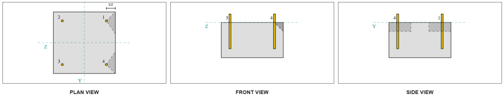
Because of the symmetric design, the anchors resisting Vz shear are also identified as single anchors. Let’s consider Anchor 1 again for the calculations.
To calculate the perpendicular load on Anchor 1, we divide the Vz shear by the total number of anchors nearest to the edge only. To calculate the parallel load on Anchor 1, we divide the Vy shear by the total number of anchors.
\(
V_{\perp} = \frac{V_{z}}{n_{a,s}}
= \frac{5 \,\text{kN}}{2}
= 2.5 \,\text{kN}
\)
\(
V_{\parallel} = \frac{V_{y}}{n_{anc}}
= \frac{5 \,\text{kN}}{4}
= 1.25 \,\text{kN}
\)
\(
V_{Ed} = \sqrt{ \left( V_{\perp} \right)^2 + \left( V_{\parallel} \right)^2 }
\)
\(
V_{Ed} = \sqrt{ \left( 2.5 \,\text{kN} \right)^2 + \left( 1.25 \,\text{kN} \right)^2 }
= 2.7951 \,\text{kN}
\)
Using a similar approach to Check #2, the resulting breakout resistance for the edge perpendicular to Vz shear is:
\(
V_{Rd,c} = \frac{V_{Rk,c}}{\gamma_{Mc}}
= \frac{4.8435 \,\text{kN}}{1.5}
= 3.229 \,\text{kN}
\)
Since 2.7951 kN < 3.229 kN, the shear breakout capacity for Vz shear is sufficient.
Check #4: Calculate concrete pryout capacity
The calculation for the shear pryout resistance involves determining the nominal capacity of the anchors against tension breakout. The reference for tension breakout capacity is EN 1992-4:2018, Clause 7.2.1.4. A detailed discussion of tension breakout is already covered in the SkyCiv Design Example with Tension Load and will not be repeated in this design example.
From the SkyCiv software calculations, the nominal capacity of the section for tension breakout is 44.61 kN.
We then use EN 1992-4:2018, Equation 7.39a, to obtain the design characteristic resistance. Using k8 = 2, the capacity is 59.48 kN.
\(
V_{Rd,cp} = \frac{k_8 N_{cbg}}{\gamma_C}
= \frac{2 \times 44.608 \,\text{kN}}{1.5}
= 59.478 \,\text{kN}
\)
In the shear pryout check, all anchors are effective in resisting the full shear load. From the image generated by the SkyCiv software, all failure cone projections overlap with each other, making the anchors act as an anchor group.
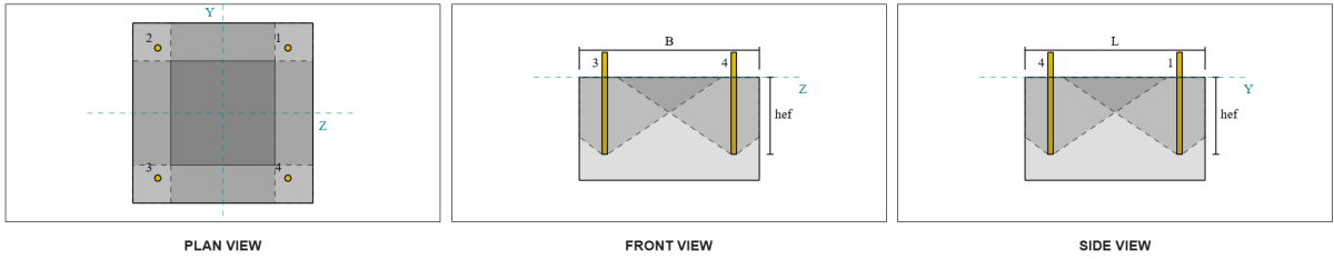
Therefore, the required resistance of the anchor group is the total resultant shear load of 7.07 kN.
\(
V_{res} = \sqrt{(V_y)^2 + (V_z)^2}
= \sqrt{(5 \,\text{kN})^2 + (5 \,\text{kN})^2}
= 7.0711 \,\text{kN}
\)
\(
V_{Ed} = \left(\frac{V_{res}}{n_{anc}}\right) n_{a,g1}
= \left(\frac{7.0711 \,\text{kN}}{4}\right) \times 4
= 7.0711 \,\text{kN}
\)
Since 7.0711 kN < 59.478 kN, the shear pryout capacity is sufficient.
Check #5: Calculate anchor rod shear capacity
The calculation of the anchor rod shear capacity depends on whether the shear load is applied with a moment arm. To determine this, we refer to EN 1992-4:2018, Clause 6.2.2.3, where the thickness and material of the grout, the number of fasteners in the design, the spacing of the fasteners, and other factors are checked.
The SkyCiv Base Plate Design software performs all the necessary checks to determine whether the shear load acts with or without a lever arm. For this design example, it is determined that the shear load is not applied with a lever arm. Therefore, we use EN 1992-4:2018, Clause 7.2.2.3.1, for the capacity equations.
We begin by calculating the characteristic resistance of the steel fastener using EN 1992-4:2018, Equation 7.34.
\(
V^0_{Rk,s} = k_6 A_s f_{u,anc}
= 0.5 \times 113.1 \,\text{mm}^2 \times 800 \,\text{MPa}
= 45.239 \,\text{kN}
\)
Next, we apply the factor for the ductility of the single anchor or the anchor group, taking k7 = 1.
\(
V_{Rk,s} = k_7 V^{0}_{Rk,s}
= 1 \times 45.239 \,\text{kN}
= 45.239 \,\text{kN}
\)
We then obtain the partial factor for steel shear failure using EN 1992-4:2018, Table 4.1. For an anchor with 8.8 material, the resulting partial factor is:
\(
\gamma_{Ms,shear}
= \max \left( 1.0 \left( \frac{F_{u,anc}}{F_{y,anc}} \right), \, 1.25 \right)
= \max \left( 1 \times \frac{800 \,\text{MPa}}{640 \,\text{MPa}}, \, 1.25 \right)
= 1.25
\)
Applying this factor to the characteristic resistance, the design resistance is 36.19 kN.
\(
V_{Rd,s} = \frac{V_{Rk,s}}{\gamma_{Ms,shear}}
= \frac{45.239 \,\text{kN}}{1.25}
= 36.191 \,\text{kN}
\)
The required shear resistance per anchor rod is the resultant shear load divided by the total number of anchor rods, which calculates to 1.77 kN.
\(
V_{Ed} = \frac{\sqrt{ (V_y)^2 + (V_z)^2 }}{n_{anc}}
\)
\(
V_{Ed} = \frac{\sqrt{ (5 \,\text{kN})^2 + (5 \,\text{kN})^2 }}{4}
= 1.7678 \,\text{kN}
\)
Since 1.7678 kN < 36.191 kN, the anchor rod steel shear capacity is sufficient.
Check #6: Calculate base plate bearing capacity
An additional base plate bearing resistance check was introduced in a later update of the software. Please refer to this link for a sample calculation and detailed explanation.
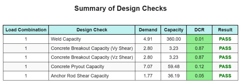
Design Summary
The SkyCiv Base Plate Design software can automatically generate a step-by-step calculation report for this design example. It also provides a summary of the checks performed and their resulting ratios, making the information easy to understand at a glance. Below is a sample summary table, which is included in the report.
SkyCiv Sample Report
See the level of detail and clarity you can expect from a SkyCiv Base Plate Design Report. The report includes all key design checks, equations, and results presented in a clear and easy-to-read format. It is fully compliant with design standards. Click below to view a sample report generated using the SkyCiv Base Plate Calculator.
Purchase Base Plate Software
Purchase the full version of the base plate design module on its own without any other SkyCiv modules. This gives you a full set of results for Base Plate Design, including detailed reports and more functionality.