Base Plate Design Example using CSA S16:19 and CSA A23.3:19
Problem Statement
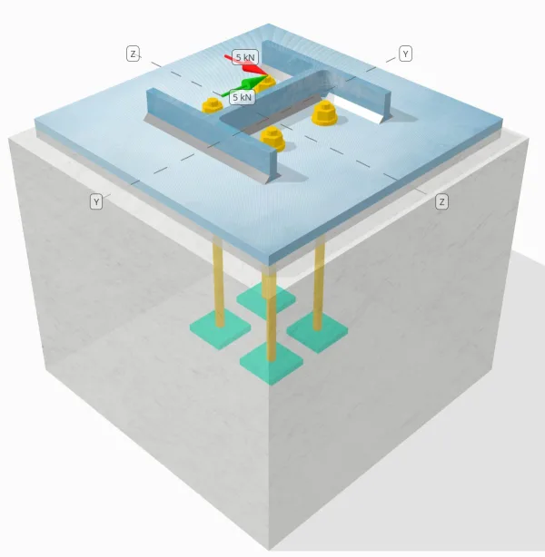
Determine whether the designed column-to-base plate connection is sufficient for a Vy=5-kN and Vz=5-kN shear loads.
Given Data
Column:
Column section: HP200x54
Column area: 6840.0 mm2
Column material: 350W
Base Plate:
Base plate dimensions: 400 mm x 400 mm
Base plate thickness: 13 mm
Base plate material: 300W
Grout:
Grout Thickness: 13 mm
Concrete:
Concrete dimensions: 450 mm x 450 mm
Concrete thickness: 380 mm
Concrete material: 20.68 MPa
Cracked or Uncracked: Cracked
Anchors:
Anchor diameter: 12.7 mm
Effective embedment length: 300 mm
Plate washer thickness: 0 mm
Plate washer connection: No
Welds:
Weld size: 8 mm
Filler metal classification: E43XX
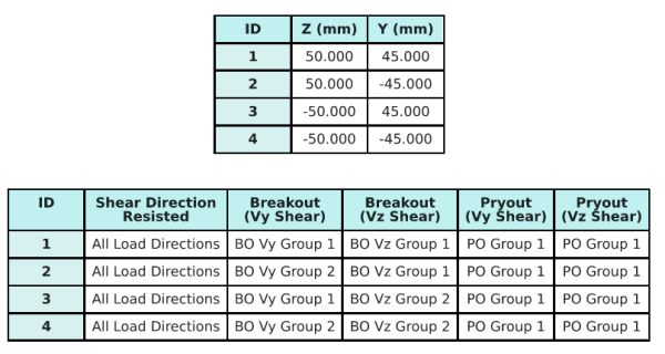
Anchor Data (from SkyCiv Calculator):
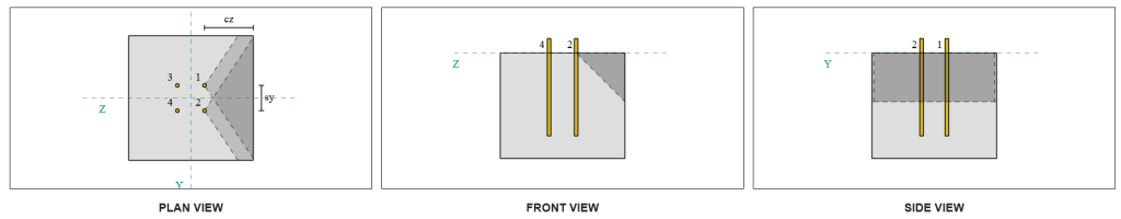
Model in SkyCiv Free Tool
Model the base plate design above using our free online tool today! No sign-up required.
Definitions
Load Path:
The design follows the CSA A23.3:2019 standards and the recommendations of AISC Design Guide 1, 3rd Edition. Shear loads applied to the column are transferred to the base plate through the welds, and then to the supporting concrete through the anchor rods. Friction and shear lugs are not considered in this example, as these mechanisms are not supported in the current software.
By default, the applied shear load is distributed to all anchors, either through the use of welded plate washers or by other engineering means. The load carried by each anchor is determined using the three (3) cases stated in CSA A23.3:2019 Clause D.7.2.1 and Figure D.13. Each anchor then transfers the load to the supporting concrete below. The load distribution in accordance with these references is also used when checking the anchor steel shear strength to ensure continuity in the load transfer assumptions.
As an alternative, the software allows a simplified and more conservative assumption, where the entire shear load is assigned only to the anchors nearest the loaded edge. In this case, the shear capacity check is performed on these edge anchors alone, ensuring that potential shear failure is conservatively addressed.
Anchor Groups:
The SkyCiv Base Plate Design Software includes an intuitive feature that identifies which anchors are part of an anchor group for evaluating concrete shear breakout and concrete shear pryout failures.
An anchor group is defined as two or more anchors with overlapping projected resistance areas. In this case, the anchors act together, and their combined resistance is checked against the applied load on the group.
A single anchor is defined as an anchor whose projected resistance area does not overlap with any other. In this case, the anchor acts alone, and the applied shear force on that anchor is checked directly against its individual resistance.
This distinction allows the software to capture both group behavior and individual anchor performance when assessing shear-related failure modes.
Step-by-Step Calculations
Check #1: Calculate weld capacity
The first step is to calculate the total weld length available to resist shear. The total weld length, Lweld , is obtained by summing the welds on all sides.
\( L_{weld} = 2b_f + 2(d_{col} – 2t_f – 2r_{col}) + 2(b_f – t_w – 2r_{col}) \)
\( L_{weld} = 2 \times 207,\text{mm} + 2 \times (204,\text{mm} – 2 \times 11.3,\text{mm} – 2 \times 9.7,\text{mm}) + 2 \times (207,\text{mm} – 11.3,\text{mm} – 2 \times 9.7,\text{mm}) = 1090.6,\text{mm} \)
Using this weld length, the applied shear forces in the y- and z-directions are divided to determine the average shear force per unit length in each direction:
\( v_{fy} = \frac{V_y}{L_{weld}} = \frac{5,\text{kN}}{1090.6,\text{mm}} = 0.0045846,\text{kN/mm} \)
\( v_{fz} = \frac{V_z}{L_{weld}} = \frac{5,\text{kN}}{1090.6,\text{mm}} = 0.0045846,\text{kN/mm} \)
The resultant shear demand per unit length is then determined using the square root of the sum of the squares (SRSS) method.
\( v_f = \sqrt{\left((v_{fy})^2\right) + \left((v_{fz})^2\right)} \)
\( v_f = \sqrt{\left((0.0045846,\text{kN/mm})^2\right) + \left((0.0045846,\text{kN/mm})^2\right)} = 0.0064836,\text{kN/mm} \)
Next, the weld capacity is calculated using CSA S16:19 Clause 13.13.2.2, with the directional strength coefficient taken as kds=1.0 to be conservative. The weld capacity for an 8mm weld on both the flanges and web is:
\( v_r = 0.67\phi t_{w,flange}X_u = 0.67 \times 0.67 \times 5.657,\text{mm} \times 430,\text{MPa} = 1.092,\text{kN/mm} \)
\( v_r = 0.67\phi t_{w,web}X_u = 0.67 \times 0.67 \times 5.657,\text{mm} \times 430,\text{MPa} = 1.092,\text{kN/mm} \)
The governing fillet weld capacity is:
\( v_{r,fillet} = \min(v_r, v_i) = \min(1.092\,\text{kN/mm}, 1.092\,\text{kN/mm}) = 1.092\,\text{kN/mm} \)
For this welded connection, the electrode strength does not overmatch the base metal strengths. Therefore, the base metal check is not governing and does not need to be performed.
Since 0.0064 kN/mm < 1.092 kN/mm, the factored weld capacity is sufficient.
Check #2: Calculate concrete breakout capacity due to Vy shear
Perpendicular Edge Capacity:
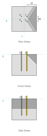
Using the ca1 values of each anchor to project the failure cones, the software identified that the failure cones of these anchors overlap. Therefore, we can treat them as an anchor group. Referring to CSA A23.3:19 Fig. D.13, because s<ca1 , we use Case 3 to determine the resistance of the anchor group against shear breakout. Furthermore, the support was determined not to be a narrow member, so the ca1 distance is used directly without modification.
Case 3:
The total force to be considered for Case 3 is the full shear force along the Vy direction. This shear force is applied to the front anchors only.
\( V_{fa\perp,case3} = V_y = 5\,\text{kN} \)
To calculate the capacity of the anchor group, we use CSA A23.3:19 Clause D.7.2. The maximum projected area for a single anchor is calculated using Equation D.34 with the actual ca dimension.
\( A_{Vco} = 4.5(c_{a1,g1})^2 = 4.5 \times (180\,\text{mm})^2 = 145800\,\text{mm}^2 \)
To get the actual projected area of the anchor group, we first determine the width of the failure surface:
\( B_{Vc} = \min(c_{\text{left},g1}, 1.5c_{a1,g1}) + (\min(s_{\text{sum},x,g1}, 3c_{a1,g1}(n_{x,g1} – 1))) + \min(c_{\text{right},g1}, 1.5c_{a1,g1}) \)
\( B_{Vc} = \min(175\,\text{mm}, 1.5 \times 180\,\text{mm}) + (\min(100\,\text{mm}, 3 \times 180\,\text{mm} \times (2-1))) + \min(175\,\text{mm}, 1.5 \times 180\,\text{mm}) \)
\( B_{Vc} = 450\,\text{mm} \)
The height of the failure surface is:
\( H_{Vc} = \min(1.5c_{a1,g1}, t_{\text{conc}}) = \min(1.5 \times 180\,\text{mm}, 380\,\text{mm}) = 270\,\text{mm} \)
This gives the total area as:
\( A_{Vc} = B_{Vc}.H_{Vc} = 450\,\text{mm} \times 270\,\text{mm} = 121500\,\text{mm}^2 \)
We then use CSA A23.3:19 Equations D.35 and D.36 to obtain the basic single anchor breakout strength.
\( V_{br1} = 0.58\left(\frac{\min(l_e, 8d_a)}{d_a}\right)^{0.2}\sqrt{\frac{d_a}{mm}}\phi\lambda_a\sqrt{\frac{f’_c}{MPa}}\left(\frac{c_{a1,g1}}{mm}\right)^{1.5}R(N) \)
\( V_{br1} = 0.58 \times \left(\frac{\min(300\,\text{mm}, 8 \times 12.7\,\text{mm})}{12.7\,\text{mm}}\right)^{0.2} \times \sqrt{\frac{12.7\,\text{mm}}{1\,\text{mm}}} \times 0.65 \times 1 \times \sqrt{\frac{20.68\,\text{MPa}}{1\,\text{MPa}}} \times \left(\frac{180\,\text{mm}}{1\,\text{mm}}\right)^{1.5} \times 1 \times 0.001\,\text{kN} \)
\( V_{br1} = 22.364\,\text{kN} \)
\( V_{br2} = 3.75\lambda_a\phi\sqrt{\frac{f’_c}{MPa}}\left(\frac{c_{a1,g1}}{mm}\right)^{1.5}R(N) \)
\( V_{br2} = 3.75 \times 1 \times 0.65 \times \sqrt{\frac{20.68\,\text{MPa}}{1\,\text{MPa}}} \times \left(\frac{180\,\text{mm}}{1\,\text{mm}}\right)^{1.5} \times 1 \times 0.001\,\text{kN} = 26.769\,\text{kN} \)
The governing capacity between the two conditions is:
\( V_{br} = \min(V_{\text{br1}}, V_{\text{br2}}) = \min(22.364\,\text{kN}, 26.769\,\text{kN}) = 22.364\,\text{kN} \)
Next, we calculate the eccentricity factor, edge effect factor, and thickness factor using CSA A23.3:19 Clauses D.7.2.5, D.7.2.6, and D.7.2.8.
The eccentricity factor is:
\( \Psi_{ec,V} = \min\left(1.0, \frac{1}{1 + \frac{2e’_N}{3c_{a1,g1}}}\right) = \min\left(1, \frac{1}{1 + \frac{2\times0}{3\times180\,\text{mm}}}\right) = 1 \)
The edge effect factor is:
\( \Psi_{ed,V} = \min\left(1.0, 0.7 + 0.3\left(\frac{c_{a2,g1}}{1.5c_{a1,g1}}\right)\right) = \min\left(1, 0.7 + 0.3 \times \left(\frac{175\,\text{mm}}{1.5 \times 180\,\text{mm}}\right)\right) = 0.89444 \)
The thickness factor is:
\( \Psi_{h,V} = \max\left(\sqrt{\frac{1.5c_{a1,g1}}{t_{\text{conc}}}}, 1.0\right) = \max\left(\sqrt{\frac{1.5 \times 180\,\text{mm}}{380\,\text{mm}}}, 1\right) = 1 \)
Finally, the breakout strength of the anchor group, calculated using CSA A23.3:19 Clause D.7.2.1, is:
\( V_{cbg\perp} = \left(\frac{A_{Vc}}{A_{Vco}}\right)\Psi_{ec,V}\Psi_{ed,V}\Psi_{c,V}\Psi_{h,V}V_{br} \)
\( V_{cbg\perp} = \left(\frac{121500\,\text{mm}^2}{145800\,\text{mm}^2}\right) \times 1 \times 0.89444 \times 1 \times 1 \times 22.364\,\text{kN} = 16.669\,\text{kN} \)
The calculated capacity for Vy shear in the perpendicular direction is 16.669 kN.
Parallel Edge Capacity:
Failure along the edge parallel to the load is also possible in this scenario, so the concrete breakout capacity for the parallel edge must be determined. The anchors involved are different due to the new failure cone projection. Based on the figure below, the failure cone projections overlap; therefore, the anchors are again treated as an anchor group.
Case 3:
The Case to use is still Case 3 since s<ca1. Therefore, the load taken by this anchor group is the full Vy shear load.
\( V_{fa\perp,case3} = V_y = 5\,\text{kN} \)
We then follow the same steps as for the perpendicular capacity.
The failure surface for an individual anchor is:
\( A_{Vco} = 4.5(c_{a1,g1})^2 = 4.5 \times (175\,\text{mm})^2 = 137810\,\text{mm}^2 \)
The actual failure surface of the anchor group is:
\( B_{Vc} = \min(c_{\text{bottom},g1}, 1.5c_{a1,g1}) + (\min(s_{\text{sum},y,g1}, 3c_{a1,g1}(n_{y,g1} – 1))) + \min(c_{\text{top},g1}, 1.5c_{a1,g1}) \)
\( B_{Vc} = \min(180\,\text{mm}, 1.5 \times 175\,\text{mm}) + (\min(90\,\text{mm}, 3 \times 175\,\text{mm} \times (2-1))) + \min(180\,\text{mm}, 1.5 \times 175\,\text{mm}) \)
\( B_{Vc} = 450\,\text{mm} \)
\( H_{Vc} = \min(1.5c_{a1,g1}, t_{\text{conc}}) = \min(1.5 \times 175\,\text{mm}, 380\,\text{mm}) = 262.5\,\text{mm} \)
\( A_{Vc} = B_{Vc}H_{Vc} = 450\,\text{mm} \times 262.5\,\text{mm} = 118130\,\text{mm}^2 \)
Similarly, the basic single anchor breakout strengths are calculated as follows:
\( V_{br1} = 0.58\left(\frac{\min(l_e, 8d_a)}{d_a}\right)^{0.2}\sqrt{\frac{d_a}{mm}}\phi\lambda_a\sqrt{\frac{f’_c}{MPa}}\left(\frac{c_{a1,g1}}{mm}\right)^{1.5}R(N) \)
\( V_{br1} = 0.58 \times \left(\frac{\min(300\,\text{mm}, 8 \times 12.7\,\text{mm})}{12.7\,\text{mm}}\right)^{0.2} \times \sqrt{\frac{12.7\,\text{mm}}{1\,\text{mm}}} \times 0.65 \times 1 \times \sqrt{\frac{20.68\,\text{MPa}}{1\,\text{MPa}}} \times \left(\frac{175\,\text{mm}}{1\,\text{mm}}\right)^{1.5} \times 1 \times 0.001\,\text{kN} \)
\( V_{br1} = 21.438\,\text{kN} \)
\( V_{br2} = 3.75\lambda_a\phi\sqrt{\frac{f’_c}{MPa}}\left(\frac{c_{a1,g1}}{mm}\right)^{1.5}R(N) \)
\( V_{br2} = 3.75 \times 1 \times 0.65 \times \sqrt{\frac{20.68\,\text{MPa}}{1\,\text{MPa}}} \times \left(\frac{175\,\text{mm}}{1\,\text{mm}}\right)^{1.5} \times 1 \times 0.001\,\text{kN} = 25.661\,\text{kN} \)
The governing strength is:
\( V_{br} = \min(V_{\text{br1}}, V_{\text{br2}}) = \min(21.438\,\text{kN}, 25.661\,\text{kN}) = 21.438\,\text{kN} \)
We then calculate the eccentricity factor and thickness factor:
\( \Psi_{ec,V} = \min\left(1.0, \frac{1}{1 + \frac{2e’_N}{3c_{a1,g1}}}\right) = \min\left(1, \frac{1}{1 + \frac{2\times0}{3\times175\,\text{mm}}}\right) = 1 \)
\( \Psi_{h,V} = \max\left(\sqrt{\frac{1.5c_{a1,g1}}{t_{\text{conc}}}}, 1.0\right) = \max\left(\sqrt{\frac{1.5 \times 175\,\text{mm}}{380\,\text{mm}}}, 1\right) = 1 \)
For the breakout edge effect factor, we take it as 1.0 per CSA A23.3:19 Clause D.7.2.1c. In addition, the value of the breakout capacity for the perpendicular edge is taken as twice the calculated value using Equation D.33 (for an anchor group).
The factored breakout capacity of the anchor group is:
\( V_{cbgr\parallel} = 2\left(\frac{A_{Vc}}{A_{Vco}}\right)\Psi_{ec,V}\Psi_{ed,V}\Psi_{c,V}\Psi_{h,V}V_{br} \)
\( V_{cbgr\parallel} = 2 \times \left(\frac{118130\,\text{mm}^2}{137810\,\text{mm}^2}\right) \times 1 \times 1 \times 1 \times 1 \times 21.438\,\text{kN} = 36.752\,\text{kN} \)
- For the perpendicular edge failure, since 5 kN < 16.7 kN, the concrete shear breakout capacity is sufficient.
- For the parallel edge failure, since 5 kN < 36.8 kN, the concrete shear breakout capacity is sufficient.
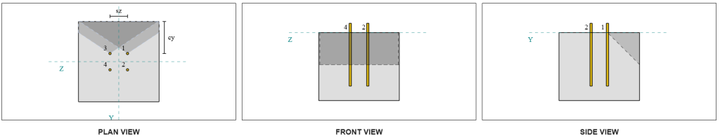
Calculate concrete breakout capacity due to Vz shear
The base plate is also subjected to Vz shear, so the failure edges perpendicular and parallel to the Vz shear must be checked. Using the same approach, the perpendicular and parallel capacities are calculated as 16.6 kN and 37.3 kN, respectively.
Perpendicular Edge:
Parallel Edge:
These capacities are then compared to the required strengths.
- For the perpendicular edge failure, since 5 kN < 16.6 kN, the factored concrete shear breakout capacity is sufficient.
- For the parallel edge failure, since 5 kN < 37.3 kN, the factored concrete shear breakout capacity is sufficient.
Check #4: Calculate concrete pryout capacity
The concrete cone for pryout failure is the same cone used in the tensile breakout check. To calculate the shear pryout capacity, the nominal tensile breakout strength of the single anchors or anchor group must first be determined. Detailed calculations for the tensile breakout check are already covered in the SkyCiv Design Examples for Tension Load and will not be repeated here.
It is important to note that the anchor group determination for shear breakout is different from that for shear pryout. The anchors in the design must still be checked to determine whether they act as a group or as single anchors. The classification of the support as a narrow section must also be verified and should follow the same conditions used for tension breakout.
According to the SkyCiv software, the nominal tensile breakout strength of the anchor group is 60.207 kN. With a pryout factor of 2.0, the factored pryout capacity is:
\( V_{cpgr} = k_{cp}N_{cbr} = 2 \times 60.207\,\text{kN} = 120.41\,\text{kN} \)
The required strength is the resultant of the applied shear loads. Since all anchors belong to a single group, the total resultant shear is assigned to the group.
\( V_{fa} = \sqrt{((V_y)^2) + ((V_z)^2)} = \sqrt{((5\,\text{kN})^2) + ((5\,\text{kN})^2)} = 7.0711\,\text{kN} \)
\( V_{fa} = \left(\frac{V_{fa}}{n_a}\right)n_{a,g1} = \left(\frac{7.0711\,\text{kN}}{4}\right) \times 4 = 7.0711\,\text{kN} \)
Since 7.07 kN < 120.4 kN, the factored pryout capacity is sufficient.
Check #5: Calculate anchor rod shear capacity
Recall that in this design example, shear is distributed to all anchors. The total shear load per anchor is therefore the resultant of its share of the Vy load and its share of the Vz load. We also consider the governing case used in the shear breakout checks.
For Vy shear, Case 3 is governing.
\( V_{fa,y} = \frac{V_y}{n_{z,g1}} = \frac{5\,\text{kN}}{2} = 2.5\,\text{kN} \)
Similarly, for Vz shear, Case 3 is governing.
\( V_{fa,z} = \frac{V_z}{n_{y,g1}} = \frac{5\,\text{kN}}{2} = 2.5\,\text{kN} \)
This gives the shear force on the anchor rod as:
\( V_{fa} = \sqrt{((V_{fa,y})^2) + ((V_{fa,z})^2)} = \sqrt{((2.5\,\text{kN})^2) + ((2.5\,\text{kN})^2)} = 3.5355\,\text{kN} \)
In this design example, grout is present. Therefore, the anchor rod also experiences bending due to eccentric shear. To account for this, we can either apply the grout reduction factor per CSA A23.3:19 Clause D.7.1.3 or check shear–bending interaction using CSA S16:19 Clause 13.12.1.4.
For this calculation, we opted to use the 0.8 reduction factor from CSA A23.3. To allow for individual engineering judgment, the SkyCiv Base Plate software provides the option to disable this reduction factor and instead use the shear–bending interaction check. This feature can be explored using the Base Plate Free Tool.
CSA A23.3 Anchor Rod Shear Capacity:
First, we calculate the anchor rod shear capacity using CSA A23.3. The minimum tensile stress of the anchor rod is:
\( f_{uta} = \min(F_{u\_anc}, 1.9F_{y\_anc}, 860) = \min(400\,\text{MPa}, 1.9 \times 248.2\,\text{MPa}, 860.00\,\text{MPa}) = 400\,\text{MPa} \)
The factored anchor rod shear capacity, calculated using CSA A23.3:19 Equation D.31 and Clause D.7.1.3, is:
\( V_{sar,a23} = 0.8A_{se,V}\phi_s0.6f_{uta}R = 0.8 \times 92\,\text{mm}^2 \times 0.85 \times 0.6 \times 400\,\text{MPa} \times 0.75 = 11.258\,\text{kN} \)
Note that the 0.8 reduction factor is applied here due to the presence of grout. This reduced shear capacity accounts for the additional bending in the anchor rod.
CSA S16 Anchor Rod Shear Capacity:
For the CSA S16 capacity, only the shear capacity is checked, since the bending due to eccentric shear has already been accounted for in the CSA A23.3 check.
The factored shear capacity is calculated using CSA S16:19 Clause 25.3.3.3.
\( V_{r,s16} = 0.7\phi_m 0.6n A_{sr} F_{u\_anc} = 0.7 \times 0.67 \times 0.6 \times 1 \times 126.68\,\text{mm}^2 \times 400\,\text{MPa} = 14.255\,\text{kN} \)
To ensure both methods are considered, the governing capacity is taken as the lesser of the two values, which is 11.258 kN.
Since 3.54 kN < 11.258 kN, the factored anchor rod shear capacity is sufficient.
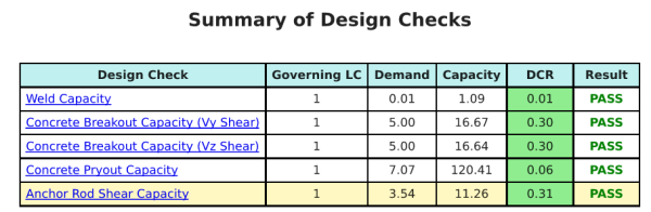
Design Summary
The SkyCiv Base Plate Design software can automatically generate a step-by-step calculation report for this design example. It also provides a summary of the checks performed and their resulting ratios, making the information easy to understand at a glance. Below is a sample summary table, which is included in the report.
SkyCiv Sample Report
See the level of detail and clarity you can expect from a SkyCiv Base Plate Design Report. The report includes all key design checks, equations, and results presented in a clear and easy-to-read format. It is fully compliant with design standards. Click below to view a sample report generated using the SkyCiv Base Plate Calculator.
Purchase Base Plate Software
Purchase the full version of the base plate design module on its own without any other SkyCiv modules. This gives you a full set of results for Base Plate Design, including detailed reports and more functionality.