Base Plate Design Example using EN 1993-1-8-2005, EN 1993-1-1-2005 and EN 1992-1-1-2004
Problem Statement
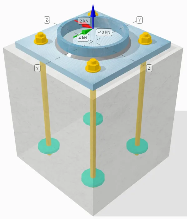
Determine whether the designed column-to-base plate connection is sufficient for a 50-kN tension load, 4-kN Vy shear load, and 2-kN Vz shear load.
Given Data
Column:
Column section: CHS193.7×10
Column area: 5770.0 mm²
Column material: S460
Base Plate:
Base plate dimensions: 300mm x 300mm
Base plate thickness: 18mm
Base plate material: S235
Grout:
Grout thickness: 0 mm
Concrete:
Concrete dimensions: 350mm x 350mm
Concrete thickness: 400 mm
Concrete material: C35/45
Cracked or Uncracked: Cracked
Anchors:
Anchor diameter: 16 mm
Effective embedment length: 350 mm
Embedded plate diameter: 70 mm
Embedded plate thickness: 10 mm
Anchor material: 4.8
Welds:
Weld type: Fillet
Weld size: 7mm
Filler metal classification: E42
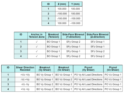
Anchor Data (from SkyCiv Calculator):
Model in SkyCiv Free Tool
Model the base plate design above using our free online tool today! No sign-up required.
Notes
The purpose of this design example is to demonstrate the step-by-step calculations for capacity checks involving concurrent shear and axial loads. Some of the required checks have already been discussed in the previous design examples. Please refer to the links provided in each section.
Step-by-Step Calculations
Check #1: Calculate weld capacity
The full tensile load is resisted by the entire weld section, while the shear load components are distributed only to a portion of the total weld length. This portion is determined by projecting a 90° sector from the center of the column to its circumference. Therefore, only half of the total circumference is designed to resist the shear load.
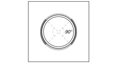
We first compute the total weld length and the portion of the weld within the 90° projection.
\(L_{weld,full} = \pi d_{col} = \pi \times 193.7\ \text{mm} = 608.53\ \text{mm}\)
\(L_{weld} = \frac{\pi d_{col}}{2} = \frac{\pi \times 193.7\ \text{mm}}{2} = 304.26\ \text{mm}\)
Next, we calculate the resultant shear load.
\(V_r = \sqrt{(V_y)^2 + (V_z)^2} = \sqrt{(4\ \text{kN})^2 + (2\ \text{kN})^2} = 4.4721\ \text{kN}\)
We then compute the normal and shear stresses, taking into account the assumed load distribution.
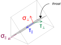
\( \sigma_{\perp} = \frac{N_x}{L_{weld,full}\,a\,\sqrt{2}} = \frac{40\ \text{kN}}{608.53\ \text{mm} \times 4.95\ \text{mm} \times \sqrt{2}} = 9.39\ \text{MPa} \)
\( \tau_{\perp} = \frac{N_x}{L_{weld,full}\,a\,\sqrt{2}} = \frac{40\ \text{kN}}{608.53\ \text{mm} \times 4.95\ \text{mm} \times \sqrt{2}} = 9.39\ \text{MPa} \)
\( \tau_{\parallel} = \frac{V_r}{L_{weld}\,a} = \frac{4.4721\ \text{kN}}{304.26\ \text{mm} \times 4.95\ \text{mm}} = 2.9693\ \text{MPa} \)
After that, we calculate the combined stresses using EN 1993-1-8:2005 Eq. (4.1).
\(F_{w,Ed1} = \sqrt{(\sigma_{\perp})^2 + 3\big((\tau_{\perp})^2 + (\tau_{\parallel})^2\big)}\)
\(F_{w,Ed1} = \sqrt{(9.39\ \text{MPa})^2 + 3\big((9.39\ \text{MPa})^2 + (2.9693\ \text{MPa})^2\big)}\)
\(F_{w,Ed1} = 19.471\ \text{MPa}\)
At the same time, we determine the stress on the base metal using the same equation.
\(F_{w,Ed2} = \sigma_{\perp} = 9.39\ \text{MPa}\)
Next, we calculate the weld capacity. We first determine the ultimate tensile strength (fu) of the weaker material, and then use EN 1993-1-8:2005 Eq. (4.1) to obtain the fillet weld resistance and base metal resistance.
\(f_u = \min\!\left(F_{u,\text{col}},\ f_{u,\text{bp}},\ f_{u,w}\right) = \min\!\left(550\ \text{MPa},\ 360\ \text{MPa},\ 500\ \text{MPa}\right) = 360\ \text{MPa}\)
\(F_{w,Rd1} = \frac{f_u}{\beta_w\,(\gamma_{M2,\text{weld}})} = \frac{360\ \text{MPa}}{0.8 \times (1.25)} = 360\ \text{MPa}\)
\(F_{w,Rd2} = \frac{0.9\,f_u}{\gamma_{M2,\text{weld}}} = \frac{0.9 \times 360\ \text{MPa}}{1.25} = 259.2\ \text{MPa}\)
Since 19.471 MPa < 360 MPa, the weld capacity is sufficient.
Check #2: Calculate base plate flexural yielding capacity due to tension load
A design example for the base plate flexural yielding capacity is already discussed in the Base Plate Design Example for Tension. Please refer to this link for the step-by-step calculation.
Check #3: Calculate concrete breakout capacity in tension
A design example for the capacity of the concrete in breakout due to tension load is already discussed in the Base Plate Design Example for Tension. Please refer to this link for the step-by-step calculation.
Check #4: Calculate anchor pullout capacity
A design example for the anchor pullout capacity is already discussed in the Base Plate Design Example for Tension. Please refer to this link for the step-by-step calculation.
Check #5: Calculate side-face blowout capacity in Y-direction
A design example for the side-face blowout capacity in Y-direction is already discussed in the Base Plate Design Example for Tension. Please refer to this link for the step-by-step calculation.
Check #6: Calculate side-face blowout capacity in Z-direction
A design example for the side-face blowout capacity in Z-direction is already discussed in the Base Plate Design Example for Tension. Please refer to this link for the step-by-step calculation.
Check #7: Calculate base plate bearing capacity at anchor holes (Vy shear)
A design example for the base plate bearing capacity in the anchor holes for Vy shear is already discussed in the Base Plate Design Example for Compression and Shear. Please refer to this link for the step-by-step calculation.
Check #8: Calculate base plate bearing capacity at anchor holes (Vz shear)
A design example for the base plate bearing capacity in the anchor holes for Vz shear is already discussed in the Base Plate Design Example for Compression and Shear. Please refer to this link for the step-by-step calculation.
Check #9: Calculate concrete breakout capacity (Vy shear)
A design example for the concrete capacity in breakout failure due to Vy shear is already discussed in the Base Plate Design Example for Shear. Please refer to this link for the step-by-step calculation.
Check #10: Calculate concrete breakout capacity (Vz shear)
A design example for the concrete capacity in breakout failure due to Vz shear is already discussed in the Base Plate Design Example for Shear. Please refer to this link for the step-by-step calculation.
Check #11: Calculate pryout capacity
A design example for the concrete pryout capacity is already discussed in the Base Plate Design Example for Shear. Please refer to this link for the step-by-step calculation.
Check #12: Calculate anchor rod shear capacity
The effect of the tension load on the anchor rod capacity is considered in this check if the shear force acts with a lever arm. However, in this example, the shear acts without a lever arm. Therefore, the interaction between shear and tensile stresses on the anchor rod will be evaluated separately in the interaction check.
For the step-by-step calculation of the shear capacity without a lever arm, please refer to this link.
The SkyCiv Base Plate Design software can perform all the necessary checks to determine whether the shear load acts with or without a lever arm. You can try out the free tool today.
Check #13: Calculate anchor steel interaction check
We use EN 1992-4:2018 Table 7.3 Eq. (7.54) to evaluate the interaction between the shear and tensile stresses on the anchor rod. By substituting the tensile stress and capacity as well as the shear stress and capacity into the equation, the resulting interaction value is:
\(I_{int} = \left(\frac{N_{Ed}}{N_{Rd,s}}\right)^2 + \left(\frac{V_{Ed}}{V_{Rd,s}}\right)^2\)
\(I_{int} = \left(\frac{10\ \text{kN}}{49.22\ \text{kN}}\right)^2 + \left(\frac{1.118\ \text{kN}}{38.604\ \text{kN}}\right)^2 = 0.042117\)
Since 0.042 < 1.0, the anchor rod steel failure interaction check is sufficient.
Check #14: Calculate concrete failure interaction check
An additional interaction check is required for concrete failures under simultaneous shear and tensile loading. For this, we use EN 1992-4:2018 Table 7.3 Eq. (7.55) and Eq. (7.56).
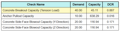
Here are the resulting ratios for all tensile checks.
Here are the resulting ratios for all shear checks.
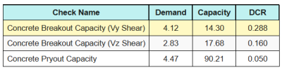
First, we check using Eq. (7.55) and compare the result to the maximum interaction limit of 1.0.
\(I_{\text{case1}} = \left(\left(\frac{N_{Ed}}{N_{Rd}}\right)^{1.5}\right) + \left(\left(\frac{V_{Ed}}{V_{Rd}}\right)^{1.5}\right)\)
\(I_{\text{case1}} = \left(\left(\frac{40}{45.106}\right)^{1.5}\right) + \left(\left(\frac{4.1231}{14.296}\right)^{1.5}\right) = 0.99\)
Next, we check using Eq. (7.56) and compare the result to the maximum interaction limit of 1.2.
\(I_{\text{case2}} = \frac{N_{Ed}}{N_{Rd}} + \frac{V_{Ed}}{V_{Rd}} = \frac{40}{45.106} + \frac{4.1231}{14.296} = 1.1752\)
Since 0.99 < 1.0 and 1.175 < 1.2, the concrete failure interaction check is sufficient.
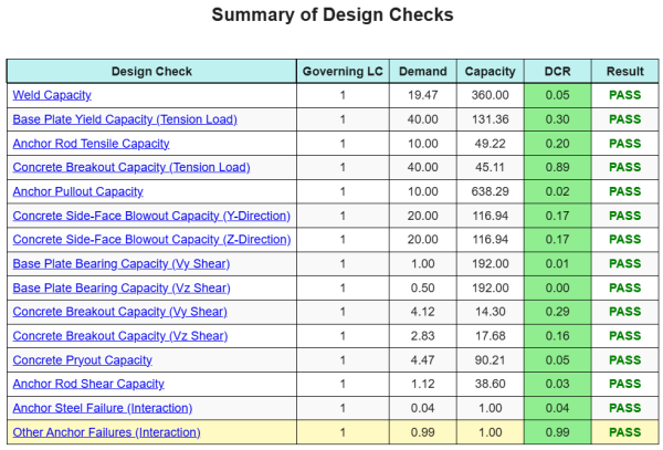
Design Summary
The SkyCiv Base Plate Design software can automatically generate a step-by-step calculation report for this design example. It also provides a summary of the checks performed and their resulting ratios, making the information easy to understand at a glance. Below is a sample summary table, which is included in the report.
SkyCiv Sample Report
See the level of detail and clarity you can expect from a SkyCiv Base Plate Design Report. The report includes all key design checks, equations, and results presented in a clear and easy-to-read format. It is fully compliant with design standards. Click below to view a sample report generated using the SkyCiv Base Plate Calculator.
(Sample report to be added soon)
Purchase Base Plate Software
Purchase the full version of the base plate design module on its own without any other SkyCiv modules. This gives you a full set of results for Base Plate Design, including detailed reports and more functionality.