Base Plate Design Example using CSA S16:19 and CSA A23.3:19
Problem Statement
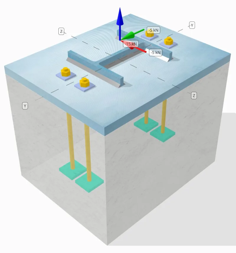
Determine whether the designed column-to-base plate connection is sufficient for 15 kN tension load, 5 kN Vy shear load, and 5 kN Vz shear load.
Given Data
Column:
Column section: HP200x54
Column area: 6840.0 mm2
Column material: 350W
Base Plate:
Base plate dimensions: 400 mm x 500 mm
Base plate thickness: 25 mm
Base plate material: 300W
Grout:
Grout Thickness: 0 mm
Concrete:
Concrete dimensions: 400 mm x 500 mm
Concrete thickness: 380 mm
Concrete material: 20.7 MPa
Cracked or Uncracked: Cracked
Anchors:
Anchor diameter: 12.7 mm
Effective embedment length: 300 mm
Anchor Ending: Rectangular Plate
Embedded plate width: 60mm
Embedded plate thickness: 10 mm
Steel Material: F1554 Gr.55
Threads in Shear Plane: Included
Welds:
Weld size: 8 mm
Filler metal classification: E43XX-X
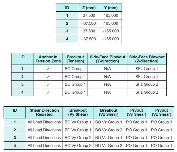
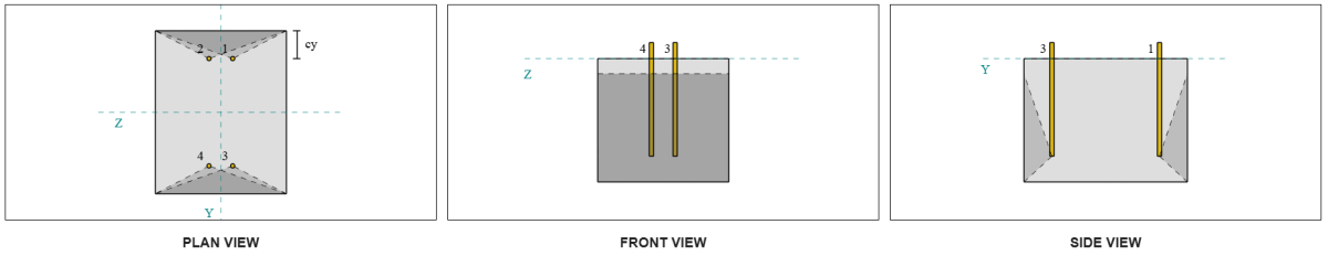
Anchor Data (from SkyCiv Calculator):
Model in SkyCiv Free Tool
Model the base plate design above using our free online tool today! No sign-up required.
Note
The purpose of this design example is to demonstrate the step-by-step calculations for capacity checks involving concurrent shear and axial loads. Some of the required checks have already been discussed in the previous design examples. Please refer to the links provided in each section.
Step-by-Step Calculations
Check #1: Calculate weld capacity
To determine the weld capacity under simultaneous loading, we first need to calculate the weld demand due to the shear load and the weld demand due to the tension load. You may refer to this link for the procedure to obtain the weld demands for shear, and this link for the tension weld demands.
For this design, the weld demand at the flange due to the tension load is found to be as follows, where the stress is expressed as force per unit length.
\( v_{f,flg} = \frac{T_{u,anchor}}{l_{eff}} = \frac{3.75\,\text{kN}}{100.5\,\text{mm}} = 0.037313\,\text{kN/mm} \)
Furthermore, the weld stress at any part of the column section due to the shear load is determined as:
\( v_{fy} = \frac{V_y}{L_{weld}} = \frac{5\,\text{kN}}{1090.6\,\text{mm}} = 0.0045846\,\text{kN/mm} \)
\( v_{fz} = \frac{V_z}{L_{weld}} = \frac{5\,\text{kN}}{1090.6\,\text{mm}} = 0.0045846\,\text{kN/mm} \)
Since there is a combination of tension and shear loads at the web, we need to obtain the resultant. Expressing this as force per unit length, we have:
\(r_f = \sqrt{(r_{f,\text{flg}})^2 + (v_{fy})^2 + (v_{fz})^2}\)
\( r_f = \sqrt{(0.037313\,\text{kN/mm})^2 + (0.0045846\,\text{kN/mm})^2 + (0.0045846\,\text{kN/mm})^2} \)
\(r_f = 0.037873\ \text{kN/mm}\)
For the web, only shear stresses are present. Thus, the resultant is:
\( r_f = \sqrt{((v_{fy})^2) + ((v_{fz})^2)} \)
\( r_f = \sqrt{((0.0045846\,\text{kN/mm})^2) + ((0.0045846\,\text{kN/mm})^2)} = 0.0064836\,\text{kN/mm} \)
Next, we calculate the factored weld capacity using CSA S16:19 Clause 13.13.2.2. We conservatively assume kds = 1.0, by always setting angle of load to 0 deg, neglecting any additional capacity added by the actual load angle.
\( v_{r,web} = 0.67\phi t_wX_u = 0.67 \times 0.67 \times 5.657\,\text{mm} \times 430\,\text{MPa} = 1.092\,\text{kN/mm} \)
\( v_{r,flg} = 0.67\phi t_wX_u = 0.67 \times 0.67 \times 5.657\,\text{mm} \times 430\,\text{MPa} = 1.092\,\text{kN/mm} \)
For this welded connection, the electrode strength does not overmatch the base metal strengths. Therefore, the base metal check is not governing and does not need to be performed.
Since 0.0064836 kN/mm < 1.092 kN/mm and 0.037873 kN/mm < 1.092 kN/mm, the weld capacity is sufficient.
Check #2: Calculate base plate flexural yielding capacity due to tension load
A design example for the base plate flexural yielding capacity is already discussed in the Base Plate Design Example for Tension. Please refer to this link for the step-by-step calculation.
Check #3: Calculate anchor rod tensile capacity
A design example for the anchor rod tensile capacity is already discussed in the Base Plate Design Example for Tension. Please refer to this link for the step-by-step calculation. Please refer to this link for the step-by-step calculation.
Check #4: Calculate concrete breakout capacity in tension
A design example for the capacity of the concrete in tension breakout is already discussed in the Base Plate Design Example for Tension. Please refer to this link for the step-by-step calculation. Please refer to this link for the step-by-step calculation.
Check #5: Calculate anchor pullout capacity
A design example for the anchor pull out capacity is already discussed in the Base Plate Design Example for Tension. Please refer to this link for the step-by-step calculation. Please refer to this link for the step-by-step calculation.
Check #6: Calculate embed plate flexural capacity
A design example for the supplementary check on the embedded plate flexural yielding capacity is already discussed in the Base Plate Design Example for Tension. Please refer to this link for the step-by-step calculation.
Check #7: Calculate side-face blowout capacity in Y-direction
Side-face blowout failure along the Y-direction is not applicable because the anchors are not located close enough to the left and right edges of the concrete support.
Check #8: Calculate side-face blowout capacity in Z-direction
To calculate the Side-Face Blowout (SFBO) capacity, we first determine the total tension force on the anchors closest to the edge. For this check, we will evaluate the capacity of the edge along the Z-direction.
Since the failure cone projections of the SFBO along the Z-direction overlap, the anchors are treated as an anchor group.
The total tension demand of the anchor group is calculated as:
\( N_{fa} = \left(\frac{N_z}{n_{a,t}}\right)n_{z,g1} = \left(\frac{15\,\text{kN}}{4}\right) \times 2 = 7.5\,\text{kN} \)
Next, we determine the edge distances:
\( c_{y,min} = \min(c_{\text{top},g1}, c_{\text{bottom},g1}) = \min(85\,\text{mm}, 415\,\text{mm}) = 85\,\text{mm} \)
\( c_{z,min} = \min(c_{\text{left},g1}, c_{\text{right},g1}) = \min(162.5\,\text{mm}, 162.5\,\text{mm}) = 162.5\,\text{mm} \)
Using these edge distances, we calculate the anchor group capacity in accordance with CSA A23.3:19 Clause D.6.4.
\( N_{sbgr} = \left(\frac{1 + \frac{c_{z,min}}{c_{y,min}}}{4} + \frac{s_{sum,z,g1}}{6c_{y,min}}\right)13.3\left(\frac{c_{y,min}}{mm}\right)\sqrt{\frac{A_{brg}}{mm^2}}\phi\lambda_a\sqrt{\frac{f’_c}{MPa}}R(N) \)
\( N_{sbgr} = \left(\frac{1 + \frac{162.5\,\text{mm}}{85\,\text{mm}}}{4} + \frac{75\,\text{mm}}{6 \times 85\,\text{mm}}\right) \times 13.3 \times \left(\frac{85\,\text{mm}}{1\,\text{mm}}\right) \times \sqrt{\frac{3473.3\,\text{mm}^2}{1\,\text{mm}^2}} \times 0.65 \times 1 \times \sqrt{\frac{20.68\,\text{MPa}}{1\,\text{MPa}}} \times 1 \times 0.001\,\text{kN} \)
\( N_{sbgr} = 172.32\,\text{kN} \)
In the original equation, a reduction factor is applied when the anchor spacing is less than 6ca₁, assuming the headed anchors have sufficient edge distance. However, in this design example, since ca₂ < 3ca₁, the SkyCiv calculator applies an additional reduction factor to account for the reduced edge capacity.
Since 7.5 kN < 172.32 kN, the SFBO capacity along the Z-direction is sufficient.
Check #9: Calculate breakout capacity (Vy shear)
A design example for the concrete breakout capacity in Vy shear is already discussed in the Base Plate Design Example for Shear. Please refer to this link for the step-by-step calculation.
Check #10: Calculate breakout capacity (Vz shear)
A design example for the concrete breakout capacity in Vy shear is already discussed in the Base Plate Design Example for Shear. Please refer to this link for the step-by-step calculation.
Check #11: Calculate pryout capacity (Vy shear)
A design example for the capacity of the concrete against pryout failure due to Vy shear is already discussed in the Base Plate Design Example for Shear. Please refer to this link for the step-by-step calculation.
Check #12: Calculate pryout capacity (Vz shear)
A design example for the capacity of the concrete against pryout failure due to Vy shear is already discussed in the Base Plate Design Example for Shear. Please refer to this link for the step-by-step calculation.
Check #13: Calculate anchor rod shear capacity
A design example for the anchor rod shear capacity is already discussed in the Base Plate Design Example for Shear. Please refer to this link for the step-by-step calculation.
Check #14: Calculate anchor rod shear and tension capacity (CSA S16)
To determine the capacity of the anchor rod under combined shear and axial loads, we use CSA S16:19 Clause 13.12.1.4.
The total tensile force experienced by the anchors, including additional bending from eccentric shear load is shown below.
\( T_{f,total} = T_f + N_{fa} = 18.038\,\text{kN} + 3.75\,\text{kN} = 21.788\,\text{kN} \)
Using the demand and capacity values for both shear and tension checks performed, we now calculate the interaction equation.
\( I = \left(\left(\frac{V_{fa}}{V_{c,zh}}\right)^2\right) + \left(\left(\frac{T_{f,total}}{T_c}\right)^2\right) \)
\( I = \left(\left(\frac{3.5355\,\text{kN}}{14.255\,\text{kN}}\right)^2\right) + \left(\left(\frac{21.788\,\text{kN}}{28.85\,\text{kN}}\right)^2\right) = 0.63189 \)
Since 0.63 < 1.0, the anchor rod interaction capacity per CSA S16 is sufficient.
Check #15: Calculate interaction checks (CSA A23.3)
When checking the anchor rod capacity under combined shear and tension loads using CSA A23.3, a different approach is applied. For completeness, we also perform the CSA A23.3 interaction checks in this calculation, which include other concrete interaction checks as well.
Here are the resulting ratios for all CSA A23.3 tension checks:
And here are the resulting ratios for all CSA A23.3 shear checks:
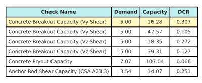
We take the design check with the largest ratio and compare it to the maximum interaction ratio using CSA A23.3:19 Equation D.46.
\( I_{int} = \frac{N_{fa}}{N_{ra}} + \frac{V_{fa}}{V_{ra}} = \frac{15}{53.52} + \frac{5}{16.278} = 0.58743 \)
Since 0.587 < 1.2, the interaction check is sufficient.
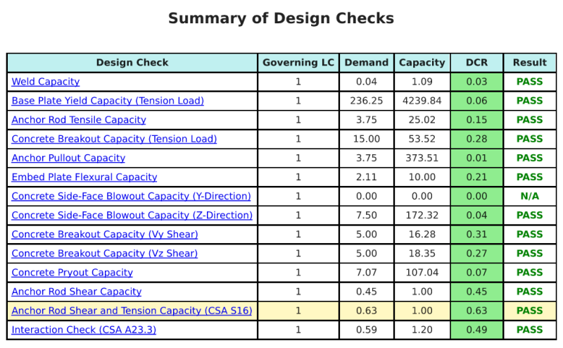
Design Summary
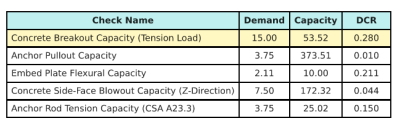
The SkyCiv Base Plate Design software can automatically generate a step-by-step calculation report for this design example. It also provides a summary of the checks performed and their resulting ratios, making the information easy to understand at a glance. Below is a sample summary table, which is included in the report.
SkyCiv Sample Report
See the level of detail and clarity you can expect from a SkyCiv Base Plate Design Report. The report includes all key design checks, equations, and results presented in a clear and easy-to-read format. It is fully compliant with design standards. Click below to view a sample report generated using the SkyCiv Base Plate Calculator.
Purchase Base Plate Software
Purchase the full version of the base plate design module on its own without any other SkyCiv modules. This gives you a full set of results for Base Plate Design, including detailed reports and more functionality.