You are probably here because you designed an anchorage using engineering software, one or more checks failed, and you were not sure what to change next.
This tutorial is written for new engineers and engineering students who want to understand anchor failure modes under ACI 318-19 and how to adjust a design logically. This is not a replacement for the code. For full provisions and requirements, always refer to ACI 318-19 Chapter 17.
The goal here is to help you recognize what is failing, why it is failing, and which design parameters actually increase capacity, instead of randomly changing inputs.
If you want to see how these checks are applied step by step in a design workflow, you may also refer to the SkyCiv Base Plate Design Software, which reports all ACI anchor checks with complete calculations.
What Is an Anchor?
An anchor is typically a steel rod embedded into concrete to connect another structural element, most commonly a steel base plate. Anchors transfer tension, shear, or combined forces from steel into the concrete support.
Anchors are commonly classified by installation method.
Cast-In Anchors
Cast-in anchors are placed before concrete is poured and become embedded as the concrete hardens.
Post-Installed Anchors
Post-installed anchors are installed into hardened concrete by drilling holes and fastening the anchor using:
- Mechanical expansion
- Adhesive or chemical bonding
Which One Is Better?
Neither anchor type is inherently better. The choice depends on constructability, project constraints, and availability. For example, if a steel column is added to an existing slab or footing, cast-in anchors are no longer an option, and post-installed anchors are typically used.
Availability also matters, as anchor types, sizes, and installation limits depend on manufacturer supply. Common anchor manufacturers include Hilti, DeWalt, and Fischer, each offering different mechanical and adhesive anchoring systems with product-specific design data and installation requirements.
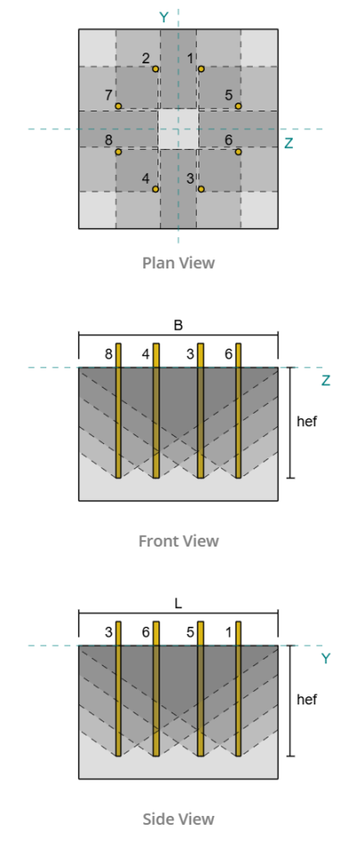
Single Anchors vs Anchor Groups
When anchor checks fail, the failure does not always occur at just one anchor. Depending on the layout, failure may occur at a single anchor or across a group of anchors acting together. ACI 318 makes this distinction because the governing failure mode and capacity can be very different.
Whether a failure is evaluated as a single anchor failure or an anchor group failure depends primarily on the overlap of projected failure surfaces. This overlap is typically controlled by anchor spacing, embedment depth, and edge distance.
To visualize this behavior during design, tools such as the SkyCiv Base Plate Design Software display projected failure areas and automatically determine whether anchors are evaluated individually or as a group based on geometry.
Single Anchors
If anchors are widely spaced or have shallow embedment depth, their projected failure areas do not overlap. In this case, failure is evaluated at the individual anchor level. One anchor may reach its limit without significant contribution from adjacent anchors.
Anchor Groups
When anchors are placed closer together with sufficient embedment depth, their projected failure surfaces overlap. In this case, the concrete limits the capacity of the entire group, and failure occurs when the combined projected failure area reaches its limit. The group capacity is not equal to the sum of individual anchor capacities.
This distinction is critical because several ACI tension and shear checks explicitly change depending on whether failure is governed by a single anchor or an anchor group. Misidentifying the governing failure type can lead to unconservative or overly conservative designs.
Design Examples
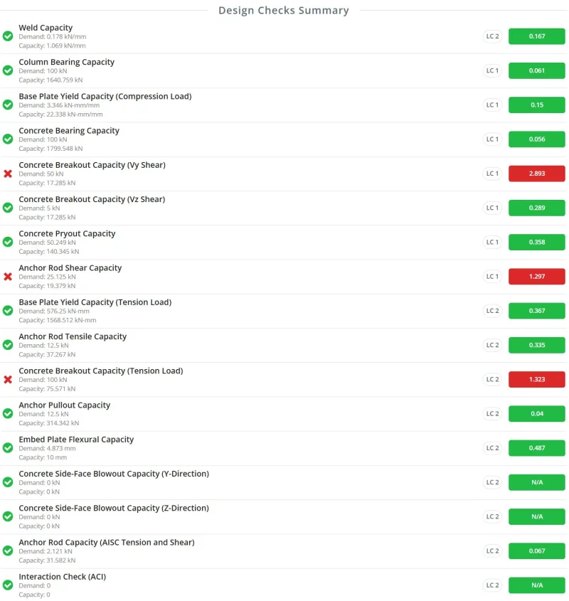
Design examples illustrating single-anchor and anchor-group failures can be found in the SkyCiv base plate design resources. Here is a sample set of design checks performed by the SkyCiv Base Plate Design Software.
Anchor Tension Checks per ACI 318-19
When anchors are subjected to tension, ACI 318-19 requires several checks. Each check corresponds to a different physical failure mechanism. Once you understand the mechanism, it becomes much easier to adjust the design.
Steel Strength in Tension
Anchor steel check considers yielding and rupture of the anchor steel.
How to Increase Steel Tensile Capacity
Choose larger anchor diameter
Larger diameters provide larger tensile area. For diameter selection, many engineers begin in the range of 1/2 inch to 3/4 inch. If demand is higher than expected, increase the diameter. This judgment improves with experience.
Increase anchor material strength
Higher material grades increase capacity but also increase cost.Common anchor materials include ASTM F1554. A practical design approach is to start with lower grades such as Grade 36, then increase to Grade 55 or Grade 105 only if required by demand.
Provide more anchors
If the anchor diameter and material grade are already maximized and the steel tension check still governs, adding more anchors in the same row may be an option. This typically requires adjusting spacing, edge distances, or base plate dimensions. Adding additional rows is permitted, but it changes load distribution and should be evaluated carefully.
Capacity Equation:
\( N_{sa} = A_{se,N} f_{uta} \)
Concrete Breakout Strength in Tension
Concrete breakout occurs when a cone-shaped portion of concrete separates from the support. In this case, the anchor steel remains intact, but the surrounding concrete fails.
This failure mode applies to headed anchors, expansion anchors, screw anchors, and undercut anchors.
How to Increase Concrete Breakout Capacity
Increase embedment depth
The breakout cone is idealized as extending from the embedded end of the anchor to the concrete surface. Increasing embedment depth enlarges the cone and significantly increases capacity. Embedment depth also directly increases the basic breakout strength defined by ACI.
Increase anchor spacing
Closely spaced anchors restrict the width of the projected failure area. Increasing spacing allows a larger effective breakout area, particularly for anchor groups.
Increase edge distance
Anchors placed near edges cannot develop a full breakout cone. Increasing edge distance often results in a noticeable capacity increase.
Use higher-strength concrete
Upgrading from a lower grade concrete to a higher grade concrete increases the basic breakout strength and is often effective when geometry is constrained.
Assume non-cracked concrete when appropriate
Uncracked concrete provides slightly higher capacity. This assumption should only be used when justified, as it changes design assumptions.
Provide reinforcement designed to carry tension
When reinforcement is explicitly designed and detailed to carry the anchor tension force, concrete breakout checks may be waived. This must be an intentional design decision, not an assumption.
Capacity Equation for Single Anchors:
\( N_{cb} = \frac{A_{Nc}}{A_{Nco}} \Psi_{ed,N} \Psi_{c,N} \Psi_{cp,N} N_b \)
Capacity Equation for Anchor Groups:
\( N_{cbg} = \frac{A_{Nc}}{A_{Nco}} \Psi_{ec,N} \Psi_{ed,N} \Psi_{c,N} \Psi_{cp,N} N_b \)
Anchor Pullout Strength
Pullout failure occurs when the anchor is pulled out of the concrete without forming a full breakout cone. This check applies to cast-in anchors and certain post-installed mechanical anchors and is evaluated for individual anchors only.
For post-installed anchors, capacity is determined through experimental testing. For cast-in anchors, capacity is generally based on anchor dimensions.
In cast-in headed studs, capacity is controlled by bearing at the embedded end, while in hooked anchors, it is controlled by the effective hook length.
How to Fix Pullout Failure
Use wider or thicker embedded plates or larger bolt heads (Headed Anchors)
For anchors with embedded ends, increasing the bearing area improves capacity. When using an embedded plate, increase the plate dimensions or thickness. For anchors with an embedded head or nut, selecting a larger head or nut at the embedded end increases the bearing area.
Extend anchor hooks or increase rod diameter (Hooked Anchors)
Short hooks or small anchor rods can lead to pullout, even if the concrete cone does not fail. Longer hooks or larger rods increase capacity and reduce the risk of pullout.
Use higher-strength concrete
Upgrading from a lower grade concrete to a higher grade concrete increases the pullout strength and is often effective when geometry is constrained.
Use non-cracking concrete when appropriate
Uncracked concrete provides better pullout resistance. This should only be assumed when justified by the design conditions.
Pullout failures are usually addressed by improving bearing conditions rather than changing spacing or edge distances.
Capacity Equation for Headed:
\( N_{pn} = \Psi_{c,p} N_p \)
where,
\( N_p = 8A_{brg}f_c’ \)
Capacity Equation for Hooked:
\( N_{pn} = \Psi_{c,p} N_p \)
where,
\( N_p = 0.9f_c’e_h d_a \)
Concrete Side-Face Blowout Strength
Side-face blowout occurs when an anchor with relatively deep embedment is placed too close to a free edge. Instead of forming a breakout cone upwards, the cone extends sideways, causing the side face of the concrete to fracture and blow out.
This failure mode is governed by the relationship between embedment depth and edge distance. When these parameters are sized in certain ways, this failure mechanism may not apply.
Since concrete cones may overlap, both single anchors and anchor groups must be checked.
How to Fix Side-Face Blowout
Increase edge distance
Increasing the edge distance improves nominal strength. Also, a much larger edge distance i.e.\( ca_1 > \frac{h_{ef}}{2.5 }\) makes this failure not applicable.
Adjust anchor spacing for anchor groups
In anchor groups, multiple anchors can cause simultaneous side-face blowout. Spacing anchors farther apart, while still allowing some cone overlap, increases the effective concrete cone size and capacity.
Reduce anchor rod embedment depth
Very long anchor rods near edges increase the likelihood of blowout. Using shorter rods relative to the edge distance can make this check not applicable.
Use higher-strength concrete
Upgrading from a lower grade concrete to a higher grade concrete increases the side-face blowout strength and is often effective when geometry is constrained.
Capacity Equation for Single Anchors:
\( N_{sb} = 160c_{a1}\sqrt{A_{brg}}\lambda_a\sqrt{f’_c} \)
Capacity Equation for Anchor Groups:
\( N_{sbg} = \left(1 + \frac{s}{6c_{a1}}\right) N_{sb} \)
Bond Strength of Adhesive Anchors
For post-installed adhesive anchors, bond strength is checked under tensile forces. The capacity is calculated based on the influence area of the bonded anchor and the characteristic bond stress. Characteristic bond stress values come from experimental testing, and if test data is unavailable, conservative values from ACI 318-19 Table 17.6.2.5 can be used.
Since influence areas can overlap, both single anchors and anchor groups must be evaluated.
The bond capacity already accounts for:
-
The bond between the anchor and the adhesive
-
The bond between the adhesive and the concrete
How to Increase Bond Capacity
Increase anchor diameter
A larger anchor diameter adds capacity to the basic bond strength, as well as the influence area. The geometry of the influence area is greatly influenced by the diameter.
Increase embedment depth
A deeper embedment increases the basic bond strength of an adhesive anchor.
Increase spacing and edge distances
For anchor groups or single anchors close to an edge, adjusting spacing and edge distances removes limitation on the total influence area.
Use an adhesive with higher characteristic bond stress
Choosing an adhesive with higher bond strength improves capacity. Larger characteristic bond stress means larger influence area, thus increasing the capacity.
Capacity Equation for Single Anchors:
\( N_a = \frac{A_{Na}}{A_{Nao}} \Psi_{ed,Na} \Psi_{cp,Na} N_{ba} \)
Capacity Equation for Anchor Groups:
\( N_{ag} = \frac{A_{Na}}{A_{Nao}} \Psi_{ec,Na} \Psi_{ed,Na} \Psi_{cp,Na} N_{ba} \)
Anchor Shear Checks per ACI 318-19
Anchor Rod Shear Capacity
Similar to the tensile capacity of anchor rods, the anchor steel check considers yielding and rupture of the anchor steel due to the applied shear load. This failure mode occurs when the steel strength of the anchor rod is reached before the surrounding concrete fails.
The shear capacity of anchor rods primarily depends on the anchor diameter, the material strength of the steel, and the number of anchors resisting the applied load.
How to Increase Steel Shear Capacity
Choose Larger Anchor Diameter
Similar to anchor tensile strength, the shear strength of anchors relies on their physical dimensions. Increasing the anchor diameter increases the cross-sectional area of the steel, which results in a higher shear capacity.
Increase Anchor Material Strength
If increasing the diameter is not possible due to geometric constraints, selecting a stronger anchor material may be considered. Common anchor rod grades include Grade 36, Grade 55, and Grade 105. Higher strength grades provide greater resistance to shear forces.
Add More Anchors
Another approach is to increase the number of anchors resisting the load. Adding more anchors distributes the applied force across additional elements and reduces the shear demand on each individual anchor.
Capacity Equation for Cast-In Headed Stud Anchor:
\( V_{sa} = A_{se,V} f_{uta} \)
Capacity Equation for Cast-In Headed Bolt and Hooked Bolt Anchor:
\( V_{sa} = 0.6A_{se,V} f_{uta} \)
If built-up grout pads are present, the shear strength of anchor rods is reduced by 80 percent according to ACI provisions.
Concrete Breakout Due to Shear
Concrete breakout strength in shear occurs when a cone-shaped portion of the concrete separates from the support due to the applied shear forces. This failure can occur when shear acts parallel to the concrete edge or perpendicular to the edge.
ACI provisions indicate that the capacity for shear parallel to an edge is generally larger than the capacity for shear acting perpendicular to the edge. However, it is still recommended to check both directions as implemented in the SkyCiv Base Plate Design Software.
How to Increase Concrete Breakout Capacity
Increase Edge Distance
Increasing the edge distance of anchors from the concrete edge allows a larger breakout cone to develop. The farther the anchors are placed from the edge, the larger the projected failure surface becomes. The basic concrete breakout strength in shear is also directly related to the edge distance.
Increase Anchor Spacing
Increasing the spacing between anchors allows the projected breakout area of the anchor group to expand. Closely spaced anchors restrict the development of the breakout cone, while larger spacing allows a larger failure surface to form.
Increase Thickness
The breakout cone may be limited by the thickness of the concrete support. If the anchor end is located too close to the bottom of the support, the breakout cone cannot fully develop. Increasing the thickness of the concrete support allows a more complete breakout projection.
Increase Anchor Length
The basic concrete breakout strength in shear is partly determined by the load-bearing length of the anchor. For anchors with constant stiffness, this length is generally equal to the anchor embedment depth. For torque-controlled expansion anchors, the load-bearing length is typically taken as twice the anchor diameter. In all cases, this length should not exceed eight times the anchor diameter.
Increase Anchor Diameter
Increasing the anchor diameter also increases the basic concrete breakout strength.
Use Higher-Strength Concrete
Using higher-strength concrete increases the basic breakout strength. This approach is often effective when geometric parameters such as spacing or edge distance cannot be easily increased.
Assume Non-Cracked Concrete When Appropriate
Concrete breakout capacity is slightly higher when the concrete is assumed to be non-cracked. This assumption should only be used when justified by the design conditions.
Provide Reinforcement Designed to Carry Tension
If reinforcement is intentionally designed and detailed to carry the anchor forces, concrete breakout may be prevented from governing. When properly designed reinforcement is provided, ACI allows the breakout check to be waived.
Capacity equation for single anchors:
\( V_{cb} = \frac{A_{Vc}}{A_{Vco}} \psi_{ed,V} \psi_{c,V} \psi_{h,V} V_b \)
Capacity equation for anchor groups:
\( V_{cbg} = \frac{A_{Vc}}{A_{Vco}} \psi_{ec,V} \psi_{ed,V} \psi_{c,V} \psi_{h,V} V_b \)
Concrete Pryout Due to Shear
Concrete pryout is another failure mode associated with anchors subjected to shear. This failure occurs when the anchor pulls a wedge-shaped portion of concrete upward due to the applied shear force.
According to ACI provisions, the concrete pryout strength is related to the concrete breakout strength in tension. This failure mode applies to several anchor types including headed anchors, expansion anchors, screw anchors, and undercut anchors.
How to Increase Concrete Pryout Capacity
Increase Embedment Depth
The breakout cone is idealized as extending from the embedded end of the anchor to the concrete surface. Increasing the embedment depth enlarges this cone and significantly increases the pryout capacity. Embedment depth also increases the basic breakout strength defined by ACI. In addition, a larger embedment depth results in a larger kcp factor used in the pryout strength calculation, which further increases the pryout capacity.
Increase Anchor Spacing
Closely spaced anchors restrict the projected breakout area. Increasing the spacing between anchors allows a larger effective breakout area to develop, especially for anchor groups.
Increase Edge Distance
Anchors located near edges cannot develop a full breakout cone. Increasing the edge distance allows the breakout surface to expand and improves the pryout capacity.
Use Higher-Strength Concrete
Using higher-strength concrete increases the basic breakout strength and can improve pryout capacity when geometric parameters cannot be modified.
Assume Non-Cracked Concrete When Appropriate
Non-cracked concrete provides slightly higher capacity. This assumption should only be used when justified by the design conditions.
Capacity equation for single anchors:
\( V_{cp} = k_{cp} N_{cp} \)
Capacity equation for anchor groups:
\( V_{cpg} = k_{cp} N_{cpg} \)
Anchor Tension and Shear Interaction Checks per ACI 318-19
This section will be published soon.