Adding tapered, non-prismatic or haunches in SkyCiv Structural 3D
A non-prismatic member has a varying cross-section along its length. This is opposed to a prismatic member which has a constant cross-section along its length. Non-prismatic members are modeled using multiple prismatic members. These include both tapers and haunches.
In Structural 3D, users can add tapered members via our Section Builder to be run in the structural analysis. In the solver, the member is broken into smaller values, with a gradual moment of inertia and polygon differences, so that accurate analysis can be performed on the members. The software UI retains this all as a single member for ease of use and convenience. 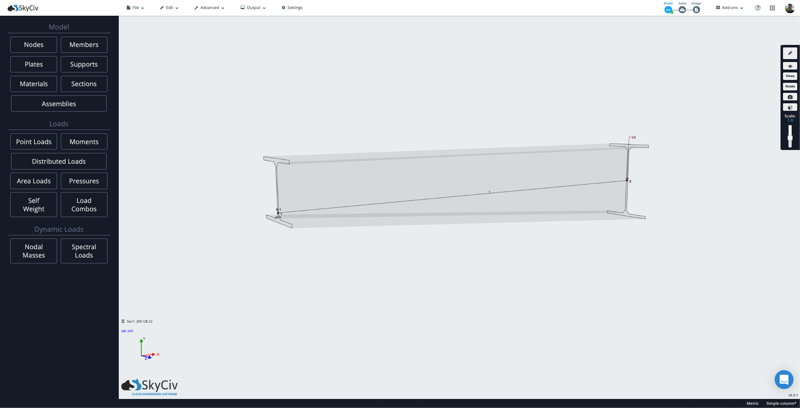
Adding a tapered beam in S3D
Tapers and haunches will only function on single, standard template shapes. Tapered sections are currently supported in the following section types:
- I Beams
- Rectangular
- Hollow Rectangular
- T Beams
Start by opening one of these template shapes from within the SkyCiv Section Builder from within Structural 3D:
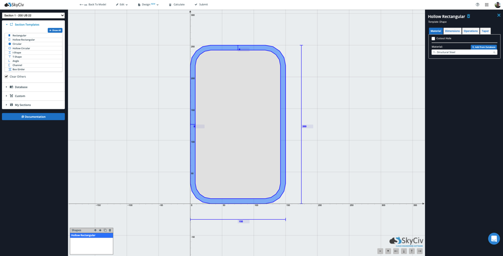
After checking on Non-Prismatic from within the Tapers tab, the options for tapered beams will display on the right:
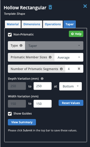
Each option has helpful tooltips to help guide you through the process, however below are the general options available:
Prismatic Member Sizes
In the solver, the member is broken into smaller segments. You can choose what section height to base the analysis on. The grey shape shows the tapered section, while the blue lines show the section heights that will be used in the analysis, based on each option:

- Maximum will take the largest section height as the basis of the taper (least conservative);
- Average will take the average section height;
- Minimum will take the smallest section height as the basis of the taper (most conservative)
Number of Prismatic Segments
This is the number of segments that the member will be broken into during the analysis. We recommend using at least 4 prismatic member segments for accurate results. The downside to using too many segments is that it can take the solver longer to automatically process them.
Depth Variation
This is the main input when controlling the taper of the member. This defines the beginning and end shape of the member ends. Here’s an example where we taper the depth of the above HSS from 250mm start to 120mm end:
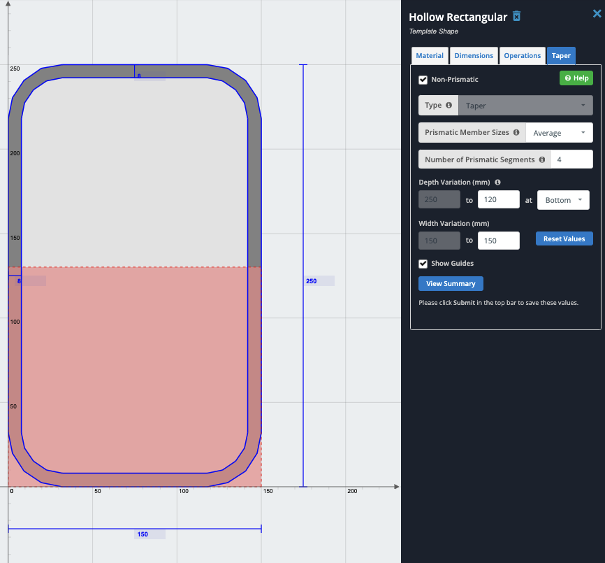
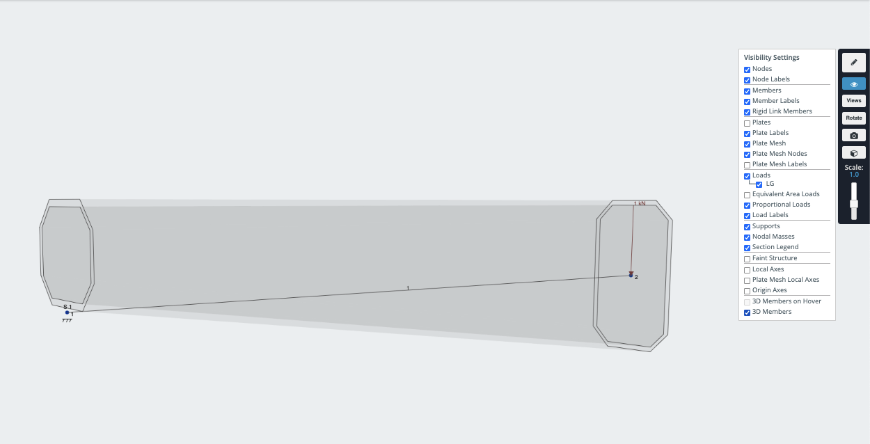
The pink square shows an estimate of the end shape. We can see in the above example, we ended at the bottom so the end shape is displayed at the bottom. Once you submit the shape, this can be confirmed and visualized by toggling on 3D Members on the right visibility settings and viewing the beam. This shows the example of how the variation is along the bottom of the beam (as per the above input) and that the top of the member remains flat:
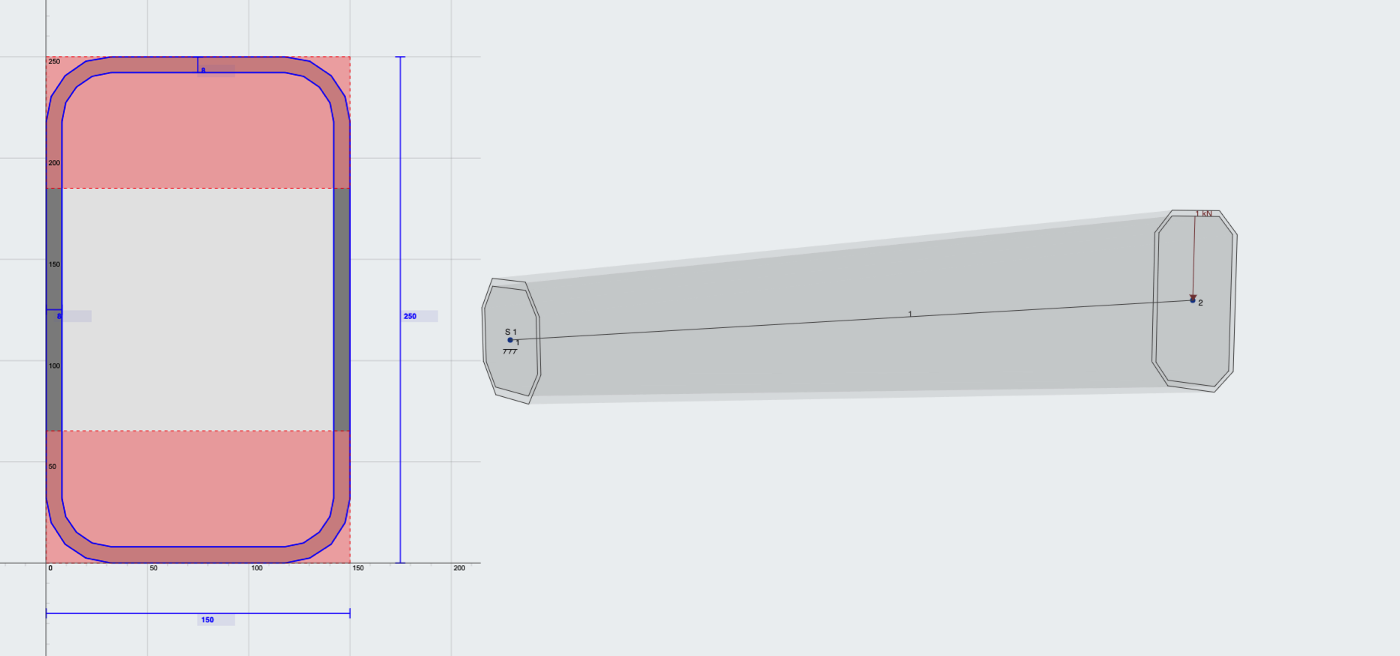
Conversely, by setting the taper to be on both top and bottom, you have the following behavior, where the beam tapers from both the top and bottom:
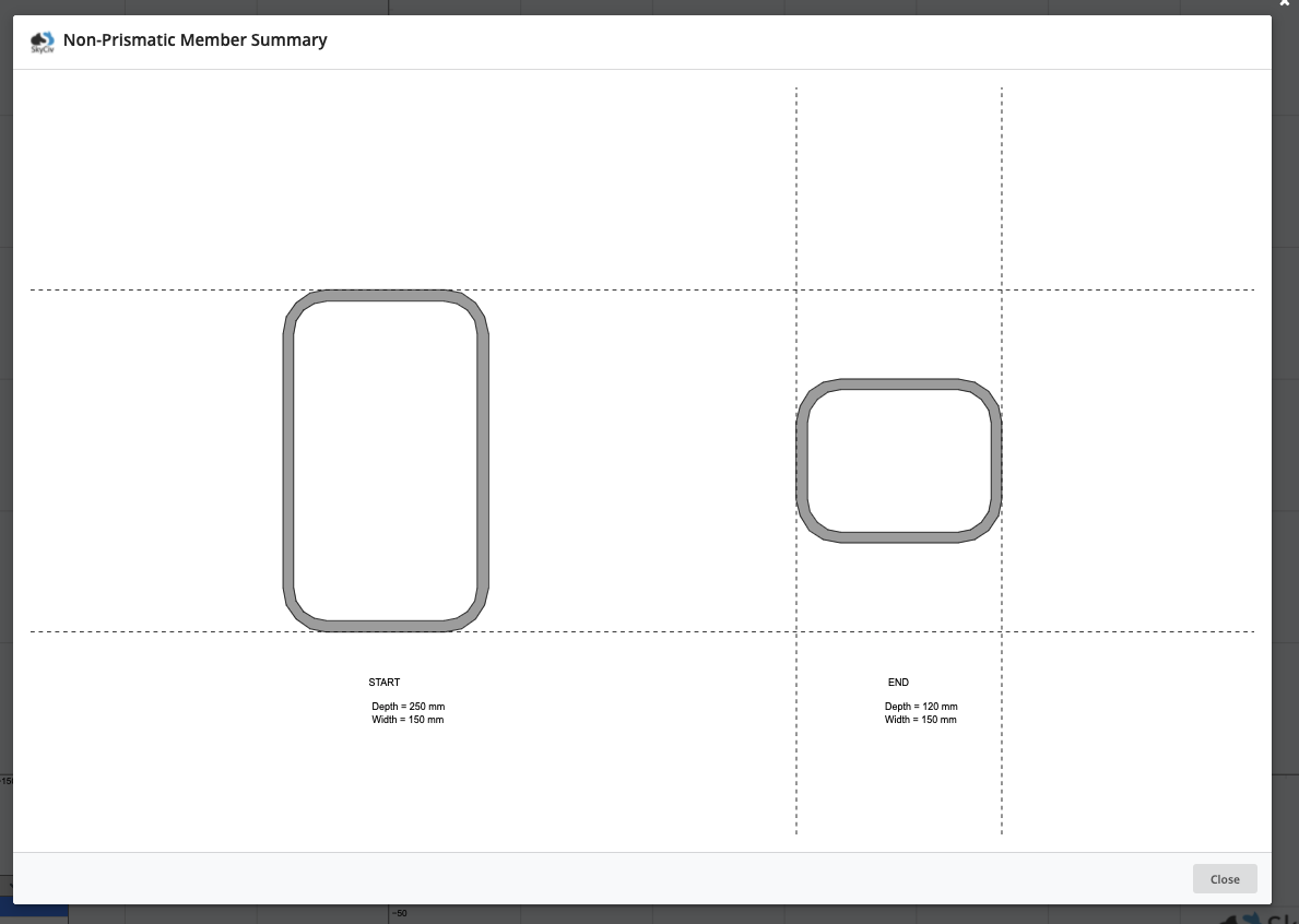
Another way to visualise this in the software is by clicking View Summary:
Haunches
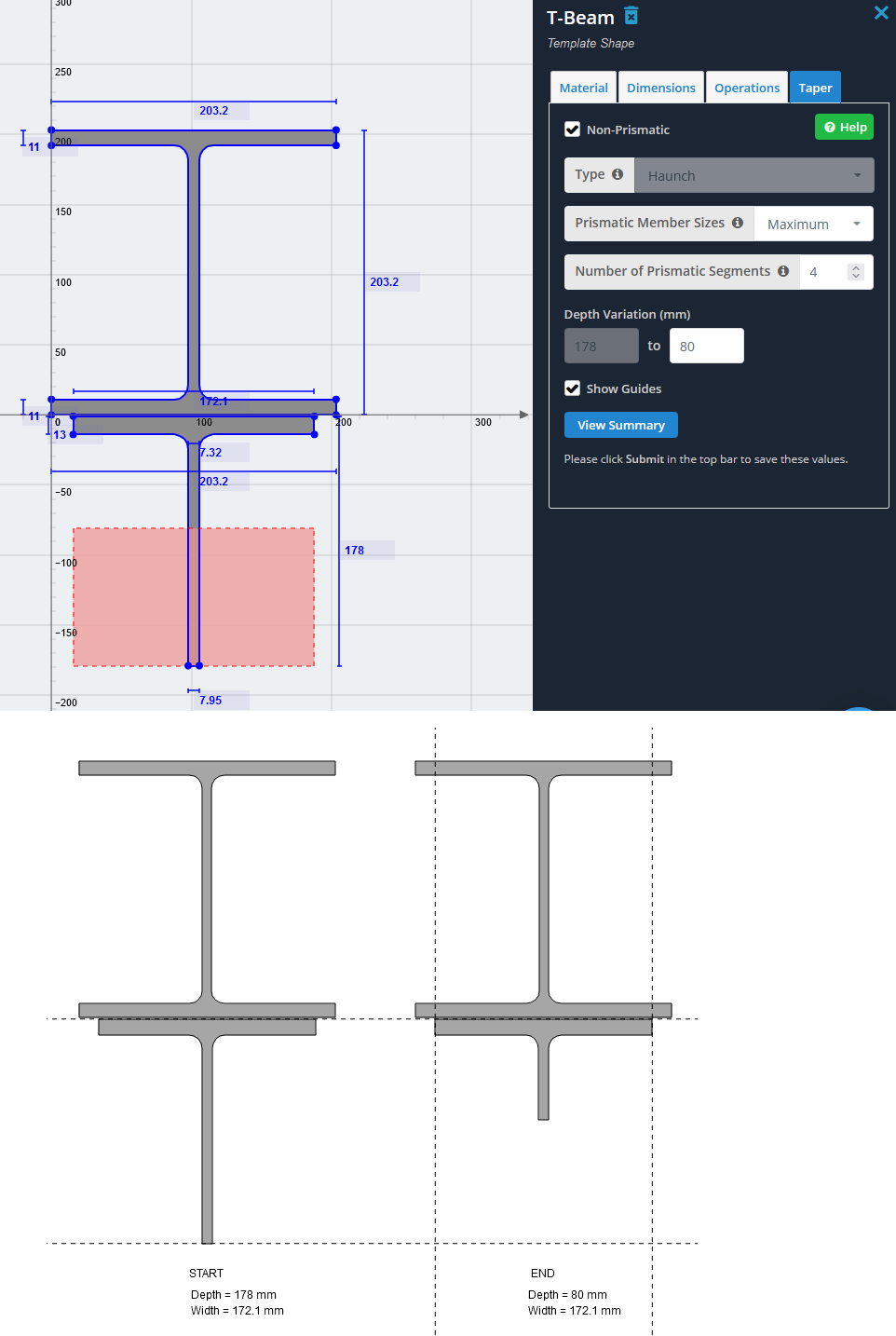
If you have two shapes, the first shape is main and the second shape is always the haunch. To add a haunch, add two shapes where the first shape is the main section and the second shape is the tapered haunch which is typically below the main section. When this is done the “Type” field will automatically be changed to “Haunch” rather than “Taper”

A haunch must be used on the SECOND of two shapes only, which is typically underneath the main section, like so:
