Knee brace connections play a vital role in reinforcing steel structures against lateral forces. Adhering to AISC 360-16 standards, these connections use both Allowable Stress Design (ASD) and Load and Resistance Factor Design (LRFD) methodologies for robust designs.
SkyCiv’s platform simplifies knee brace connection design with user-friendly tools and advanced analysis features, including a specialized Knee Brace Connection Calculator. Engineers can efficiently navigate complex challenges through an intuitive interface and cloud-based collaboration.
Advantages of Knee Brace Connection:
- Cost-Effective: Requires less material and labor, reducing construction costs.
- Efficient Load Resistance: Effectively transfers lateral forces to foundations, ensuring stability in high-wind or seismic areas.
- Easy Construction: Quicker and simpler to install, saving time on site.
- Design Flexibility: Strategically placed braces that minimally impact usable space and aesthetics.
- Retrofit-Friendly: Easily added to existing structures to enhance seismic performance.
SkyCiv’s tools, compliant with AISC 360-16, empower engineers to design safe and efficient knee brace systems, ensuring strong, resilient structures. The Knee Brace Connection Calculator streamlines the design process, making it easier to achieve optimal results.
Now onto using the SkyCiv Knee Brace Connection Calculator…
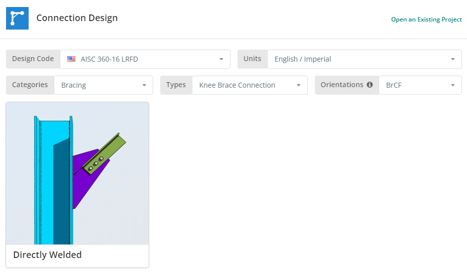
The Design Code can be AISC 360-16 ASD or LRFD. Units can be English/Imperial or SI/Metric. Now click the “Directly Welded” tile.
Project Tab
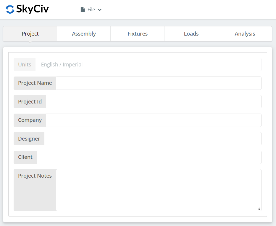
Here you can specify the details of the project you are currently working.
Assembly Tab
There are three tabs under Assembly. This is where you specify the Column or Girder, Brace, and Connection or Gusset Plate properties.
Column or Girder Tab
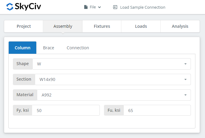
Brace Tab
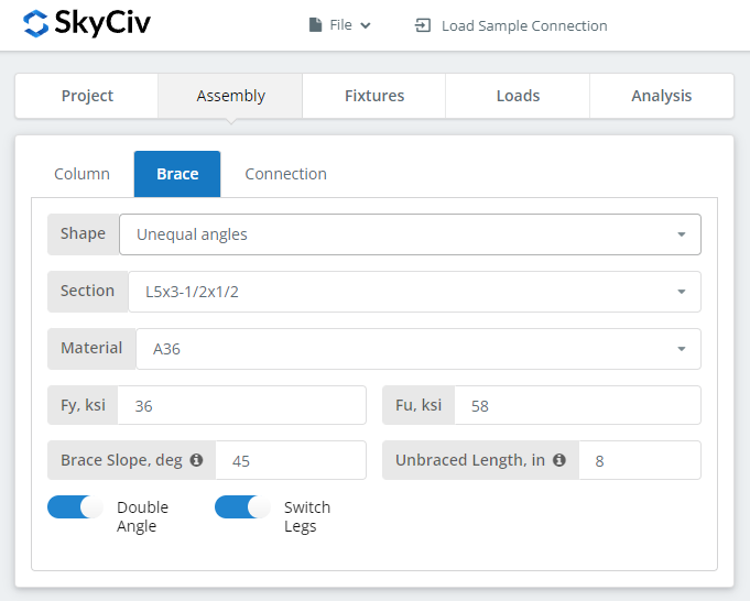
You can select many different brace shapes. Single Angles, Double Angles, Square and Rectangular HSS, and WT Sections.
Connection Tab

This is where you fill in the gusset plate properties.
Fixtures Tab
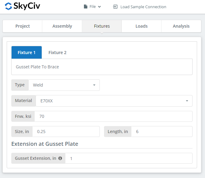
This is where you set your bolts and welds information. Gusset plate to brace and gusset plate to column or girder support information.
Loads Tab
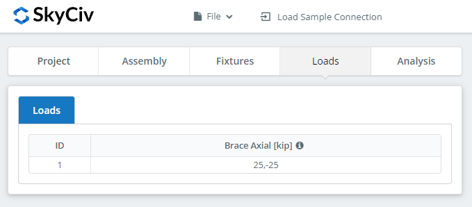
This is where you specify the loads. Make sure to hover over the tooltips for additional information.
Analysis Tab
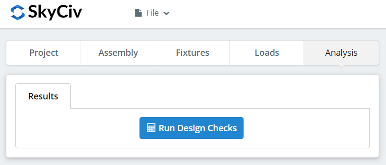
And finally, click “Run Design Checks”. If you missed any needed inputs on the previous tabs, this will notify you to fill in the missing inputs.
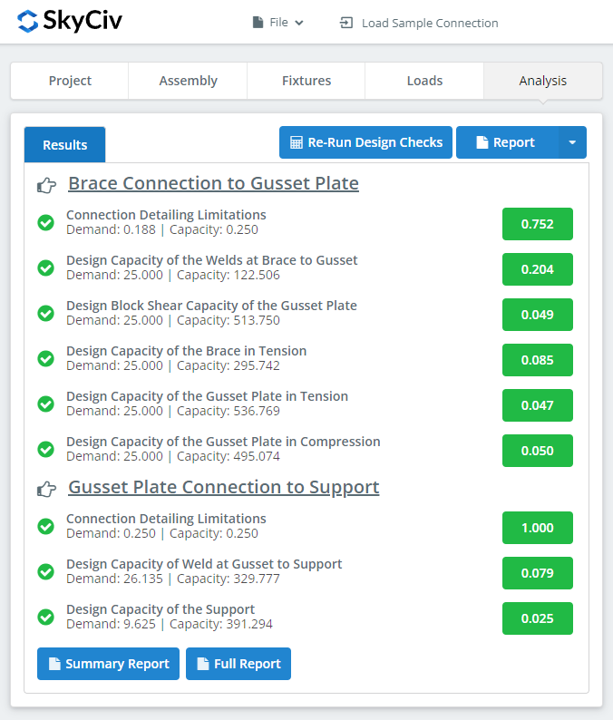
After clicking “Run Design Checks”, you can see a summary if your connection failed or not. If it failed, manually change the inputs in the previous tabs and then, click “Re-Run Design Checks”. When it’s finally okay, hover over “Report”. You can select “Summary Report” or “Full Report”, whatever fits your need.

What you see above is a snippet of the full report. As you can see, there is a reference to the AISC manual and/or specification. This should make it easier for the signing engineer to cross-check the calculations. Our calculations are very readable. It is written similar to how it’s written in the manual, specification, or design guides.
Here‘s a PDF copy of the full detailed calculation report. Check it out!


