The single plate connection is one of the five basic shear connection types presented in part 10 of the 15th Edition AISC Manual. This connection type is a fabricator-favorite since it is very cost effective. The plate is always shop-welded to the support and usually field-bolted to the connecting beam. You can also weld the plate to the connecting beam especially on a shop-welded frame assembly. Here’s a tip, do not weld the plate to the connecting beam if it means doing it on the field. Field-welding is labor-intensive thus very expensive.
Two configuration types
-
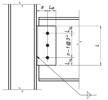
Conventional configuration
- Only a single vertical row of bolts is permitted. The number of bolts in the connection must be between 2 and 12.
- The distance from the bolt line to the weld line must be equal to or less than 3-1/2 in.
- Standard holes (STD) or horizontal short-slotted holes (HSSL) are permitted to be used as noted in Table 10-9 of the 15th Edition AISC manual.
- The vertical edge distance must satisfy AISC Specification Table J3.4 requirements. The horizontal edge distance should be greater than or equal to 2d for both plate and the beam web, where d is the bolt diameter.
- Either the plate thickness or the beam web thickness must satisfy the maximum thickness requirement given in Table 10-9 of the 15th Edition AISC manual.

-
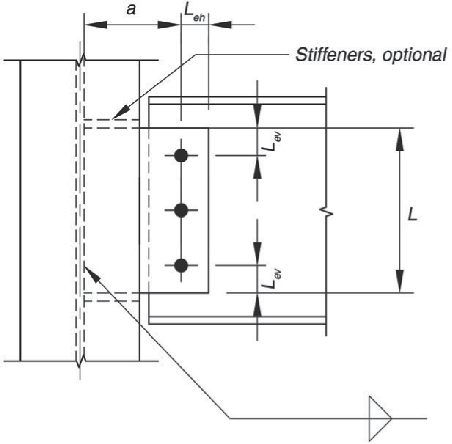
Extended Configuration
- The number of bolts is not limited.
- The distance from the weld line to the bolt line closest to the support is not limited.
- The use of holes must satisfy AISC Specification Section J3.2 requirements.
- The horizontal and vertical edge distances must satisfy AISC Specification Table J3.4 requirements.

Now onto using the software.
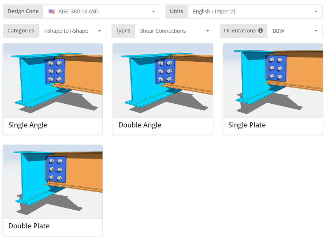
The Design Code can be AISC 360-16 ASD or LRFD. Units can be English/Imperial or SI/Metric. Orientation can either be BCF, BCW or BBW. Hover over the tooltip for more info. Now click the “Single Plate” tile.
Project Tab
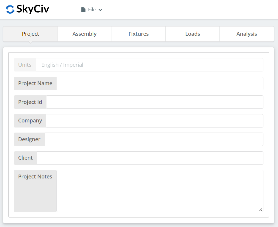
Here you can specify the details of the project you are currently working.
Assembly Tab
There are three tabs under Assembly. This is where you specify the Girder, Beam, and Connection (Single Plate) properties.
Girder Tab
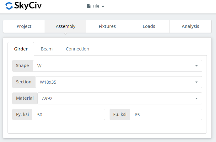
Here you can specify the section/shape of the girder and its material grade. You can either choose A992 or A36 material. But if you are using a different material, you can choose Custom and manually input the Fy and Fu values.
Beam Tab
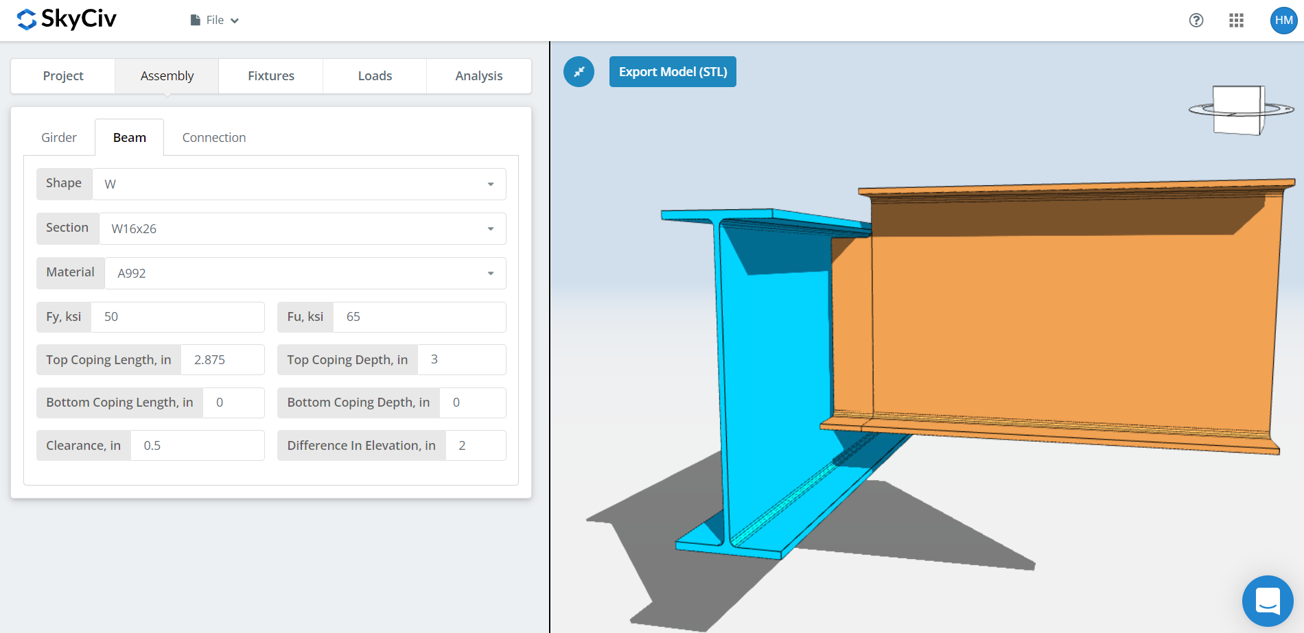
Similar to the girder tab, here you can specify the beam section/shape and material grade. In addition, you can also specify the cope dimensions as well as the beam clearance and difference in elevation. For BBW orientation, there is an automatic coping but you can also change this to your liking. Note that the automatic coping will recalculate whenever you change either the beam section, girder section, clearance, or the difference in elevation. If you select a clearance small enough that your beam is still inside the girder, this will mostly be a conventional single plate configuration unless if the girder flange is wide enough where the distance between the bolt to the girder web is greater than 3-1/2″. Otherwise, a clearance where the beam is completely outside the girder flange will automatically be an extended single plate configuration. As for the difference in elevation, a positive value means the beam is above the girder and negative if below.
Connection Tab
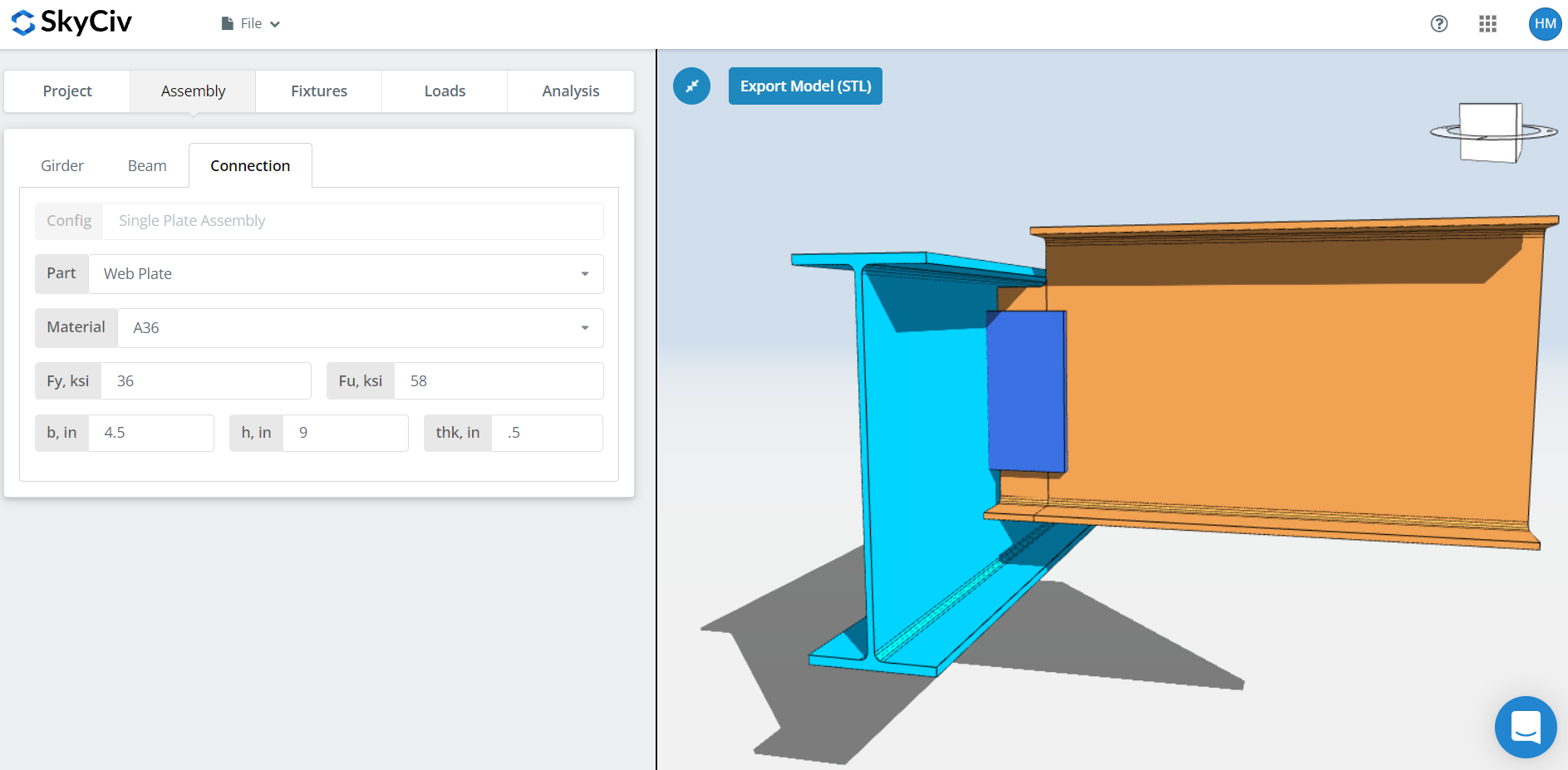
Here you can specify the properties of the web plate or single plate. Material grade of A36 or A992 but you can also specify “Custom” and manually input Fy and Fu. Set the plate width ‘b’, plate height ‘h’, and plate thickness ‘thk’. Now don’t forget to look closely at the 3D renderer and make sure the plate dimensions make sense. Plate height should be within the beam depth and plate width should be wide enough for the beam to bolt or weld to it especially on an extended plate configuration.
Fixture 1 Tab
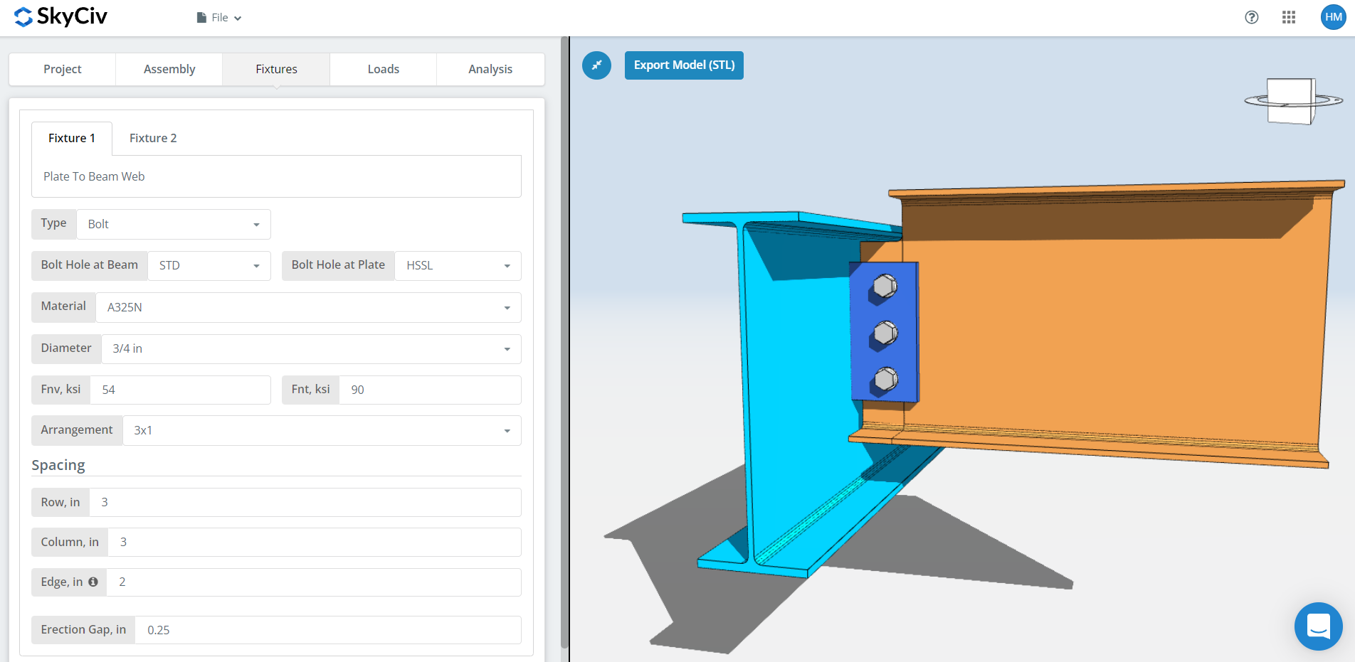
Here is where you can specify the plate to beam web connection. You can either choose bolted or welded but for this demonstration, let’s choose a bolted one.
First, specify the bolt hole types at both beam and plate. Fabricators usually prefer using standard holes (STD) at beam and horizontal short-slotted (HSSL) holes at plate to allow better fitting at the field.
Next, select the bolt material or grade. You can choose either A307, A325, A490, or a Custom input. N or X bolts for bearing-type connections and SC for slip critical connections. Note that slip critical connections generally have lesser bolt capacity. You should only use SC when there is a presumed slip in the direction of the force. In this specific example, if you use OVS holes at any of the beam or plate, the bolt will be automatically checked as slip critical. As for N versus X, X has a larger bolt shear capacity but you will have to make sure that bolt threads are excluded from the shear plane thus you will need to communicate this properly with the erector. And for SC(A) versus SC(B), SC(B) has a larger bolt capacity but you will also need a more thorough cleaning of the plies, for example, SSPC-SP6 or Commercial Blast Cleaning.
Next, specify the bolt diameter. You can choose from 5/8″ up to 1-1/2″ diameter or the equivalent metric units. Then, specify the bolt arrangement. You can choose up to 12 bolt rows and columns. Don’t forget to specify the bolt row and column spacing as well. Here’s a tip, you can use a larger bolt spacing instead of increasing the number of bolts if you need more bolt capacity. Just make sure the plate height still makes sense and within the allowable beam depth. Our bolt group strength utilizes the instantaneous center of rotation method (ICOR), which means you can specify any bolt spacing and capitalize its increase in bolt capacity. But, you need to make sure your fabricator is okay with variable bolt spacing. Some fabricators like using 3″ spacing typical. As for the “edge” input, this is the distance from the beam end to the first bolt column.
And finally, erection gap. As its name suggests, this is a gap to aid erection in the field. Just make sure you really need this gap since there is an equivalent decrease in bolt capacity.
Fixture 2 Tab
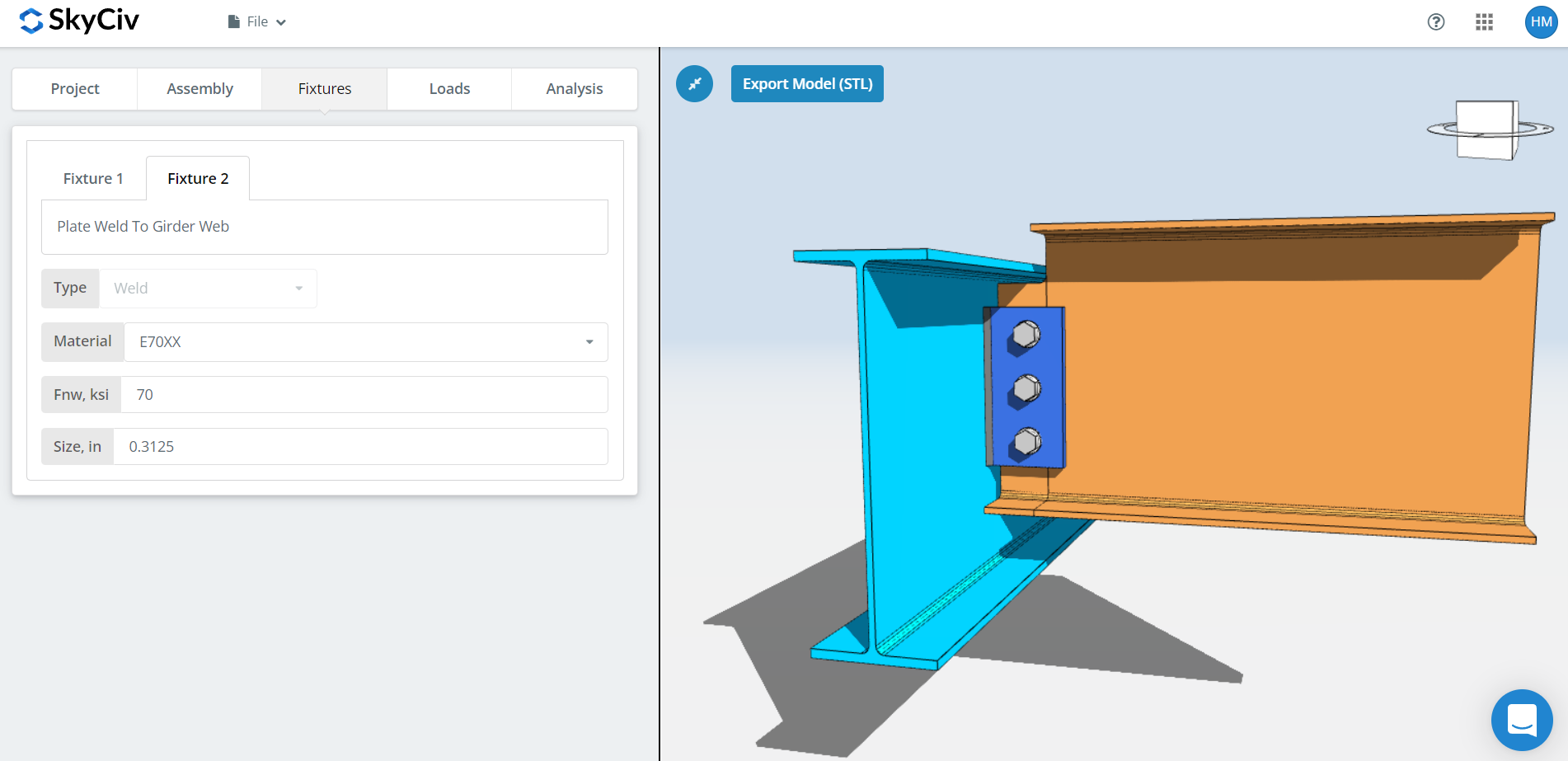
Here is where you can specify the plate to support (girder web, column flange, or column web) connection. You can only choose welded here for single plate connections. First, specify the weld material. There’s a couple of weld material options but if what you have is not there, you can use ‘Custom’ and manually input Fnw. And finally, don’t forget the weld size. For single plate connections, you will need a weld size that is at least 5/8 times the plate thickness. This is to make sure the weld develops the plate capacity. Here’s a tip, refer to Table 8-12 of the 15th Edition AISC on page 8-126. There is a big leap in number of weld passes from 5/16″ to 3/8″ fillet weld. You only need a single pass for 5/16″ but three passes on 3/8″. Which means, try sticking to a 1/2″ thick plate since this will only need a 5/16″ fillet weld to develop it. Try increasing the plate height up to the maximum allowable height first before increasing the plate thickness since a thicker plate requires a larger weld to develop it and possibly multiple weld passes. Multiple weld passes mean more weld deposits and more labor-time thus more expensive.
Loads Tab
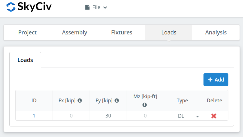
Don’t forget to input the vertical shear load under ‘Fy’.
Analysis Tab
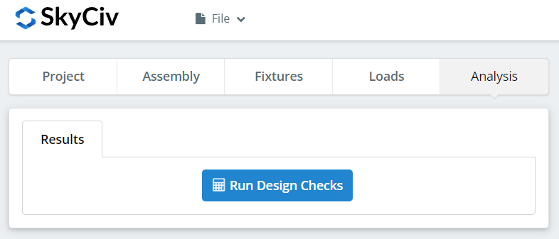
And finally, click “Run Design Checks”. If you missed any needed inputs on the previous tabs, this will notify you to fill in the missing inputs.
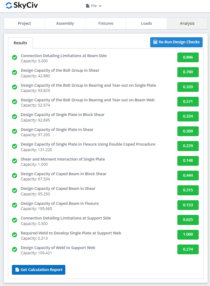
After clicking “Run Design Checks”, you can see a summary if your connection failed or not. If it failed, manually change the inputs in the previous tabs and then, click “Re-Run Design Checks”. When it’s finally okay, click “Get Calculation Report” to see the detailed report.
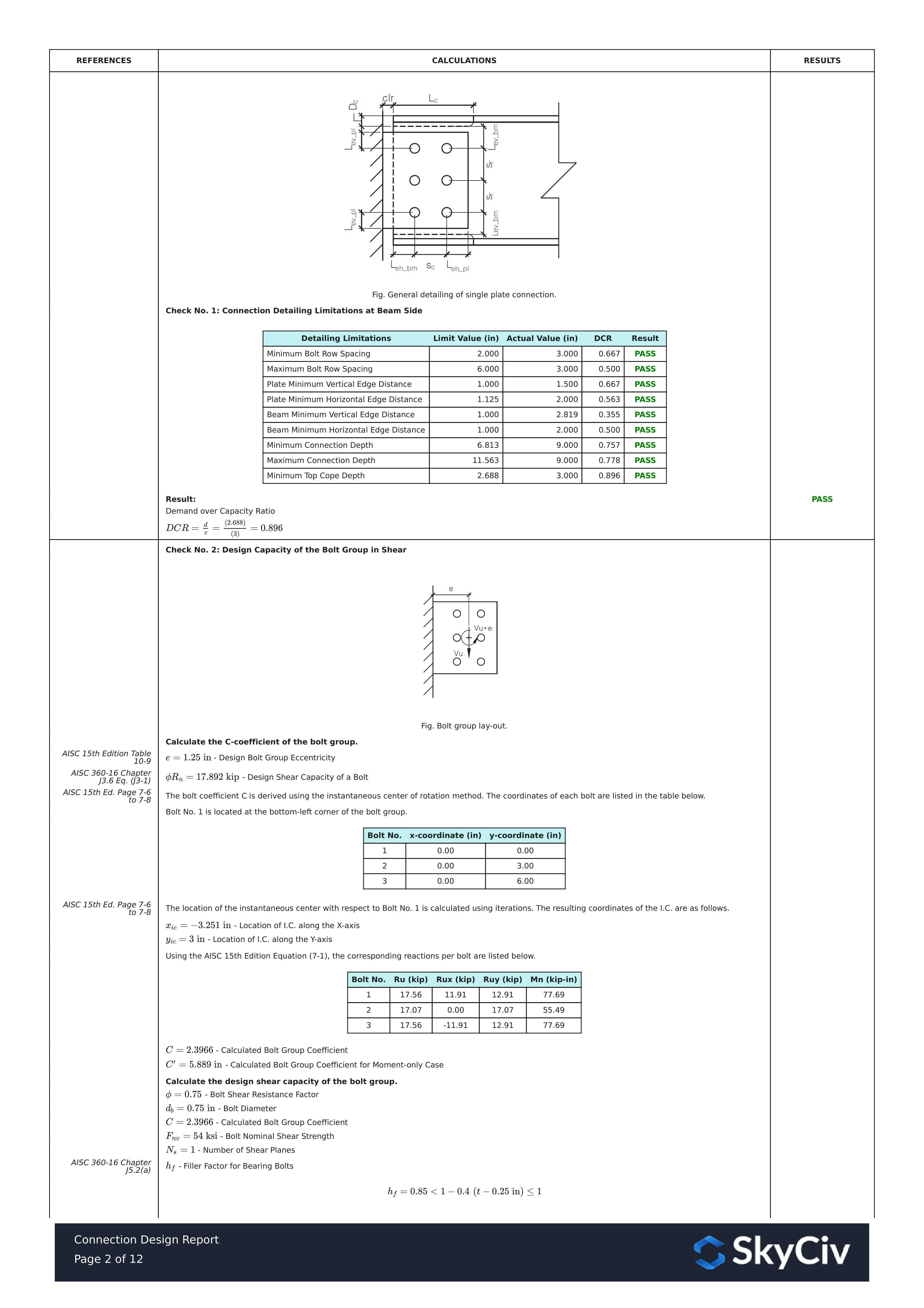
What you see above is a snippet of the detailed calculation report. As you can see, there is a reference to the AISC manual and/or specification. This should make it easier for the signing engineer to cross-check the calculations. Our calculations are very readable. It is written similar to how it’s written in the manual, specification, or design guides.
Here’s a PDF copy of the full detailed calculation report… Connection Design Report. Check it out!