How to Calculate an Indeterminate Beam – Double Integral Method
Indeterminate beams can be a challenge because of the extra steps needed for solving the reactions. Remember that indeterminate structures have what is called a degree of indeterminacy. To solve the structure, boundary conditions have to be introduced. Consequently, the higher the degree of indeterminacy, the more boundary conditions have to be identified. But before we can solve an indeterminate beam, we first need to identify if the beam is statically indeterminate. As beams are one-dimensional structures, using the equation to determine externally statically indeterminate structures is sufficient.
[math]
i_{e}=R-\left ( 3+e_{c} \right )
[math]
Where:
- ie = Degree of indeterminacy
- R = Total number of reactions
- ec = External conditions (e.g. internal hinge)
Typically, however, without the need to solve for the degree of indeterminacy, anything other than simple spans or cantilever beams are statically indeterminate, assuming such beams do not come with internal hinges.
There are many ways to approach it comes to solving indeterminate beams. Although for sake of simplicity and similarity with SkyCiv Beam’s hand calculations, we will discuss the Double Integration method.
Double Integration
Double Integration is perhaps the simplest of all methods for the analysis of beams. The concept for this method is pretty straightforward as opposed to other methods as it relies mainly on a basic understanding of integral calculus, hence the name. A bit of integral calculus is adapted from the relationship of the curvature of the beam to the moment which is shown below.
[math]
\frac{1}{\rho}=\frac{M}{EI}
[math]
Note that 1/ρ is the curvature of the beam and that ρ is the radius of the curve. Fundamentally, the definition of curvature is the rate of change of the tangent with respect to the arc length. As the moment is a function of the loading with respect to the length of the member, integrating the curvature with respect to the length of the member will yield the slope of the beam. Similarly, integrating the slope with respect to the length of the member will yield the beam deflection. As typical structural loadings are algebraic in nature, integration of these expressions is as simple as using the general power formula.
[math]
\int f\left ( x \right )^{n}dx=\frac{f\left ( x \right )^{n+1}}{n+1}+C
[math]
Perhaps the best way to understand the concept is by providing an example of a beam with the following given.

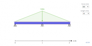
The sample beam above is an indeterminate beam with triangular loadings. With the supports, Ay, By and Cy for the first, second, and third supports respectively, the first step in solving these unknowns is by starting with the equilibrium equations.

Note that the beam has a degree of static indeterminacy of 1°. As there are four unknowns (Ax, Ay, By, and Cy) and there are three equations so far from the equilibrium equations above, it is necessary to create one more equation from the boundary conditions. Recall that the moment generated by a point load and a triangular load are the following.
Point Load:
[math]
M=F\times x; M = Fx
[math]
Triangular Load:
[math]
M=\frac{w_{0}\times x}{2}\times \left ( \frac{x}{3} \right ); M = \frac{w_{0}x^{2}}{6}
[math]
By using double integration method, these new equations are made and displayed below.

Note: The equations above are written as Macaulay functions where an expression is equal to zero when x < L. In this case, L = 1.
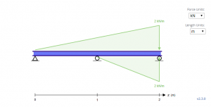
In the equations above, notice that the fourth term added seems to come out of nowhere. In fact, the direction of the loading is opposite the direction of gravity. This is due to the fact that the equations for triangular loadings only work when the load is ascending as the length increases. This is not much of an issue for equations for distributed and point loads due to their symmetry. In effect, the equivalent loading for the beam above looks like the beam below, thus the equations are based on it.

To solve for C1 and C2, the boundary conditions have to be determined. In the beam above, it can be observed that three such boundary conditions exist at x = 0, x = 1, and x = 2, where the deflection y is zero on the three locations.
Boundary Condition 1
[math]
x=0, y=0; C_{2}=0
[math]
Boundary Condition 2
[math]
x=0, y=0; C_{1}=\frac{1}{120}-\frac{A_{y}}{6}
[math]
After determining the values of each constant, the last equation can now be obtained using the last boundary condition.
Boundary Condition 3

Note that the boundary condition of θ = 0 at x = 1 can be used, although it is applicable only for the middle reaction of a symmetrical continuous beam with symmetrical loading.
As the four equations have been determined, they can now be solved simultaneously. Solving these equations will yield the following reactions.

With the reactions determined, the values of the reactions can be substituted back to the moment equation. This will allow us to determine the value of the moment in any part of the beam system.

Another convenience of Double Integration is that the moment equation is presented in a way that can be used to solve for shear with the relationship shown below.
[math]
V=\frac{dM}{dx}
[math]

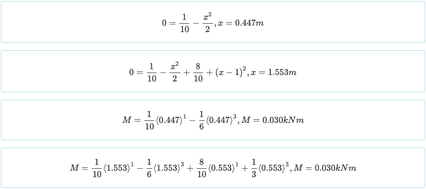
Again, using only a basic understanding of differential calculus, equating the derivative of a function to zero yields the maximum or minimum of that function. Thus, equating V = 0 will result to a maximum positive moment at x = 0.447 and x = 1.553 of M = 0.030

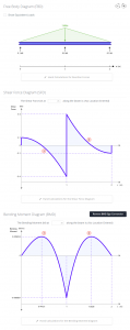
Of course, all this can be verified with SkyCiv Beam.

SkyCiv Beam Software
SkyCiv Beam Analysis Software allows users to analyze beam structures easily and accurately. You can get an analysis of your beam member, including reactions, shear force, bending moment, deflection, and stresses in a matter of seconds.
If you want to give it a try first, Free Beam Calculator is a great way to start, or simply sign up for free today!


