The following guide to the difference between LRFD and ASD will go through the following topics:
What is LRFD and ASD?
Simply put, ASD checks against allowable stresses and is an older, more traditional design process; whereas LRFD tends to be a more modern method, considering factored load forces and checking them against some maximum strength.
ASD and LRFD are methodologies or philosophies that provide a general workflow for the design of structural elements. Designing structural elements aims to safeguard the public health, safety, and general welfare of the occupants of the structure and the structure itself. This objective is fulfilled when elements in the structure are proportioned in such a way that, under certain loads, they do not reach a limit state.
Load and Resistance Factor Design (LRFD)
On the one hand, LRFD stands for Load and Resistance Factor Design. In short, it consists of proportioning structural elements using some factors to reduce their resistance such that no applicable limit state is reached when the structure is subjected to some appropriate LRFD load combinations. Those load combinations are the result of factoring the actual (nominal) loads by other factors to get ultimate state loading conditions. In the design of steel and wood structures, the term “LRFD” is used to refer to this method, however, for the design of concrete and masonry structures the term “strength design” is preferred when referring to this method.

Allowable Strength Design (ASD)
On the other hand, ASD stands for Allowable Stress Design (Also sometimes referred to as Permissible Stress Design). In summary, it consists of proportioning structural members such that elastically computed stresses at the analysis stage under nominal loads do not exceed some specified allowable stress. This method is also known as “working stress design”. Nominal loads, under which the elastic stresses are calculated, come from the ASD load combinations.

What is the difference between Serviceability and Strength?
There are two types of limit states; serviceability and strength. Serviceability limit state is reached when the structure is judged not to be useful for its intended function, this is normally associated with deflection or displacement limits. The AISC definition of Serviceability is “a state in which the function of a building, its appearance, maintainability, durability, and comfort of its occupants are preserved under normal usage.” Strength limit state is reached when the structure becomes unsafe, prior to ultimate collapse when material strength is exceeded.
In general, serviceability should be met whereas strength limits ensure safety of the structure and must be met. A good way to look at this is what is the outcome or effect of these limit states being exceeded? If the Strength Limits are reached, the structure is likely to experience some serious consequences such as buckling, instability, yielding or complete failure. If Serviceability issues are exceeded, these generally affect the people and usage of the building, for instance the occupants may feel uncomfortable if there is excessive deformations or vibrations in the building. This is not to discount the severity or seriousness of meeting serviceability checks, as these are generally contractually required, affect the building use and are extremely expensive to rectify if failure occurs.
Main differences between ASD and LRFD
Load Combinations
When using ASD, the load combinations factors do not increase the value of the service loads being combined but represent actual service loads. Most of the combinations in ASD include dead load with a unit factor, and when combined with dynamic loads like wind, snow, and earthquake, the latter are multiplied by a number less than one, accounting for a balance between the probability of nature, economics, and safety. For more information, check the ASD load combinations article.
In contrast, load combinations in LRFD do increase the values of service loads, using factors greater than one in most of the combinations. These factors account for the uncertainty about dynamic loads, and the possibility of overpassing the expected static loads during the structure’s life cycle. For more information, check the LRFD load combinations article.
Limit State Inequalities
For ASD, the limit state inequality is expressed as:
\(R_a \leq \frac{R_n}{\Omega}\)
Where \(R_a\), is the Required Strength based on the loads applied as per the ASD load combinations. \(R_n\) is the Nominal Strength provided by the checked member, and \(\Omega\) is the factor of safety. The fraction on the right corresponds to the allowable strength, which is the upper limit theoretically imposed on the structure material.
For LRFD, the limit state inequality looks like this:
\(R_a \leq \phi \cdot R_n\)
Where \(R_a\), is the Required Strength based on the loads applied as per the LRFD load combinations. \(R_n\) is the Nominal Strength provided by the checked member, and \(\phi\) is the resistance factor that varies depending on the limit state being checked. The fraction on the right corresponds to the design strength, which is the upper limit theoretically imposed on the structure material.
Available Strength
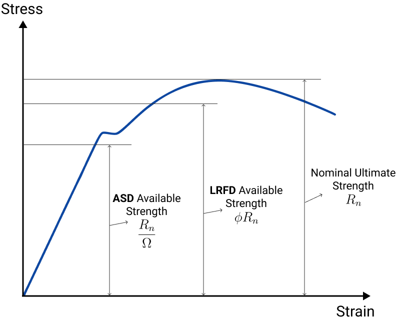
In ASD, the available strength is referred to as allowable strength, while in LRFD it is called design strength. In the limit state inequalities, it is the term on the right-hand side. Graphically, in a generic material strain-stress curve, the available strength looks as in the picture below, where the available strength for ASD is clearly lower than the one for LRFD. However, this does not mean that LRFD is always less conservative than ASD because the required strength (left-hand side of the inequality) is also scaled up by some factors in LRFD.

Factor of Safety
For the ASD philosophy, the factor of safety is taken as constant across the different load combinations, it only varies for the different limit state conditions: axial force, bending moment, torsion moment, and shear force.
For LRFD, the factor of safety is not explicit in the limit state inequality, but an effective factor of safety can be derived as follows:
\(R_a = U \cdot (R_{service\; loads}) \leq \phi \cdot R_n\)
\(R_{service\; loads} \leq \frac{R_n}{U/\phi} = \frac{R_n}{\Omega_{eff, \; LRFD}}\)
Where \(U\) are the different load factors that are specific for each load combination, therefore the effective factor of safety in LRFD varies depending on the load combination and limit state condition (bending, shear, axial, torsion) considered. That said, LRFD accounts better for the uncertainty of loads applied and the strength available, spreading the factors in the different load combinations and the limit state conditions.
Flowchart Comparison
For a further comparison between Limit State and ASD (or Permissible Stress), refer to the diagram below:

Use SkyCiv for running design checks using LRFD or ASD
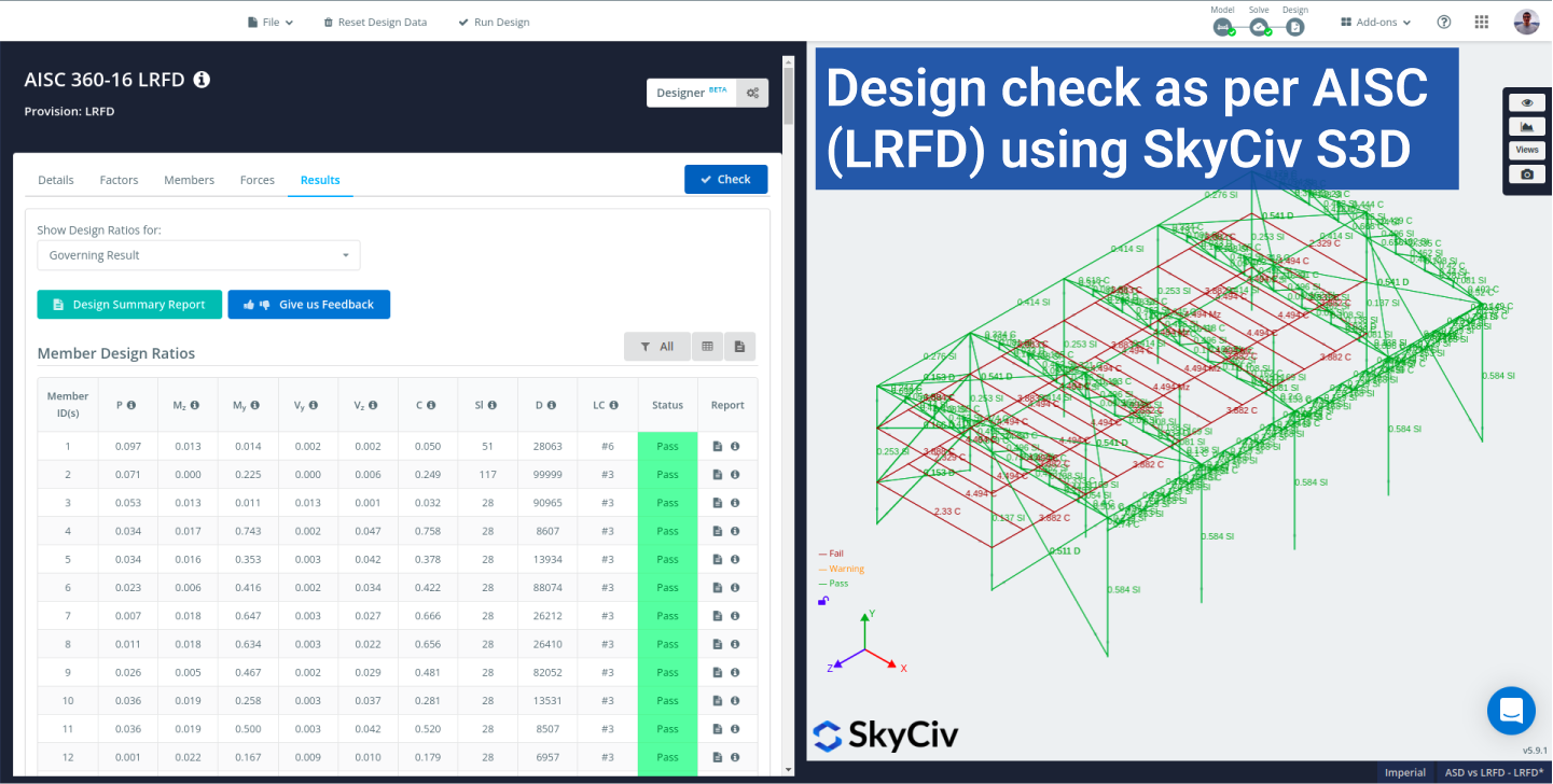
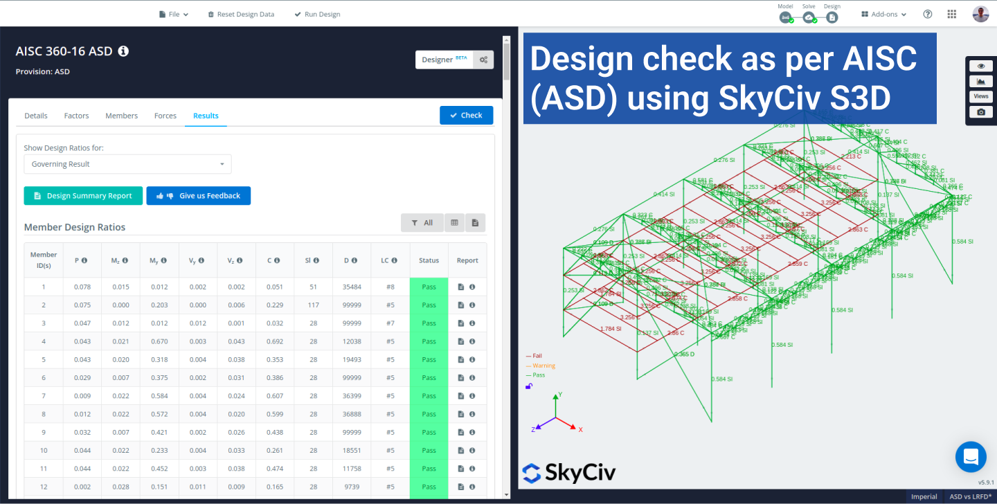
Using SkyCiv, it is possible to run design checks on a structure, using the LRFD and ASD methodologies. For both, we offer detailed calculation reports that make it easy to understand what the software is doing.

References
- 2015 International Building Code. International Code Council, 2015.
New to SkyCiv Structural 3D? Sign up today for FREE!
Product Developer
BEng (Civil)


