Introduction
The FE Plate Model type of Area Load uses the SkyCiv Finite Element (FE) solver to distribute the load over an area to equivalent loads on its supporting members.
The FE plate submodel is constructed and analysed automatically, and the shear force diagram of the members is used to determine the equivalent member loads.
The FE plate submodel area load offers the following advantages over other area load types:
- Can handle complex polygons
- Can distribute loads to portions of continuous members
- Can handle shapes with open edges
The FE plate submodel has the following limitations:
- Loads can be applied to a single ‘bay’ (polygon) only
Method of calculation – FE plate submodel
The FE plate submodel is created automatically in the following way.
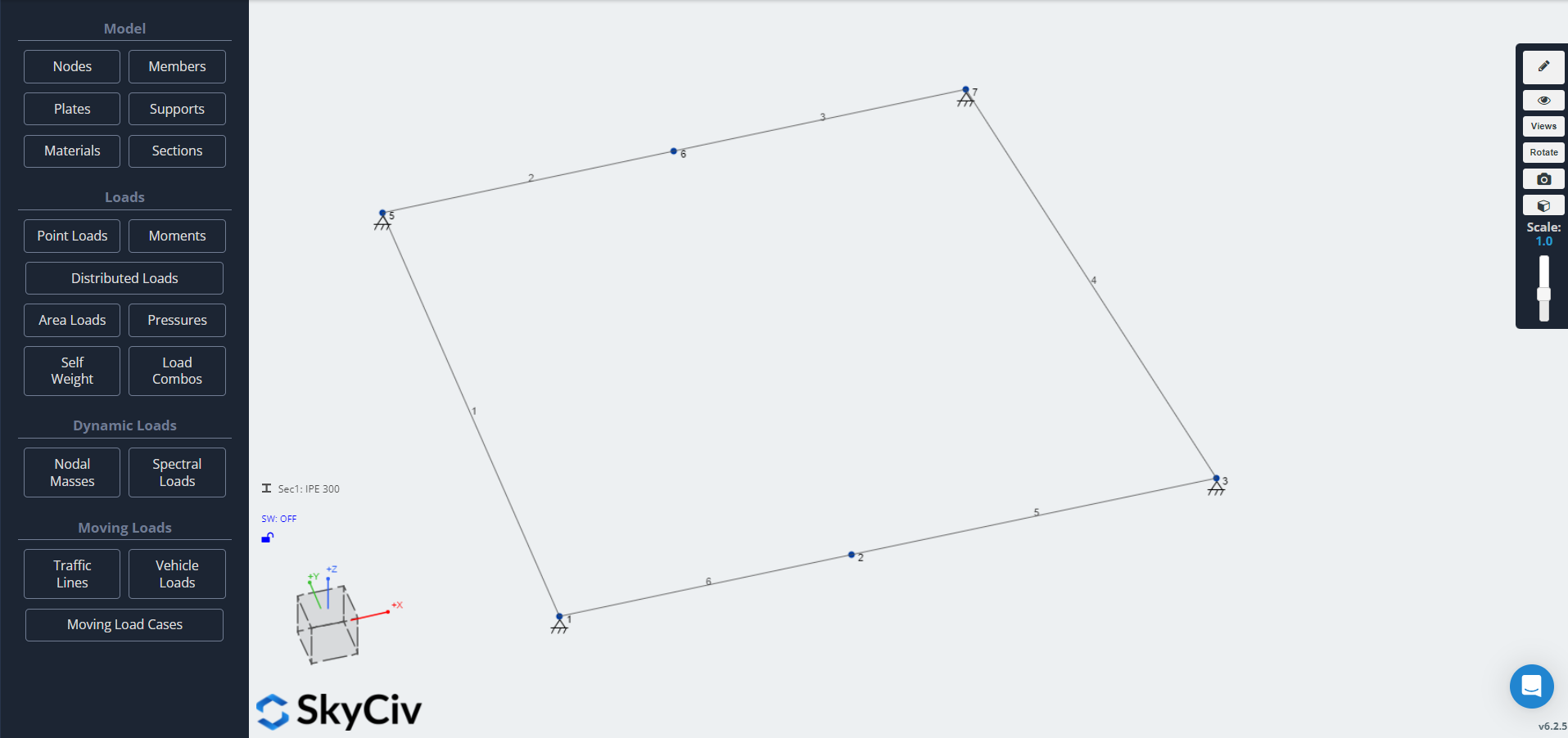
The Area Load is defined by the Corner Node IDs:
Given these Corner Node IDs, members around the periphery are detected and added to the submodel (interior members are not detected or added). At the Corner Nodes, pin supports are added:
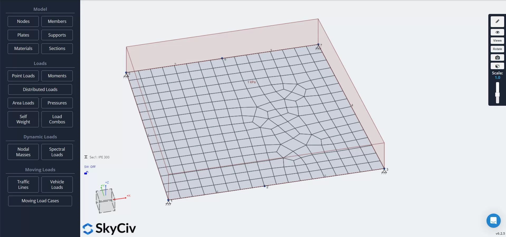
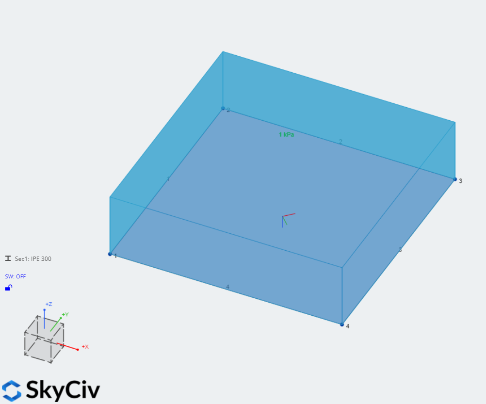
A plate is created within the area. The plate is meshed and a pressure load is applied:
The model is solved, giving the member shear force diagrams, as well as support reactions:
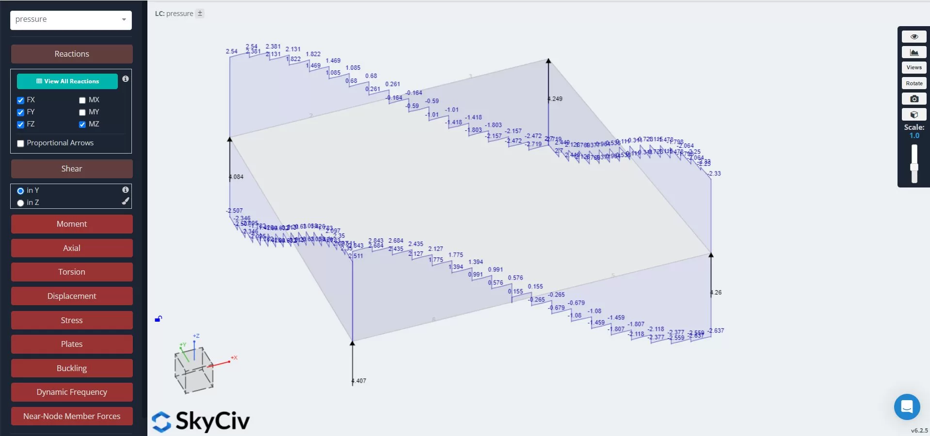
The equivalent loads are determined by looking at the shear force diagram, as well as the reactions.
Each step change in the shear force diagram gives the value of an equivalent point load. At support points, the combination of the shear force step and reaction force is used to calculate an equivalent point load.
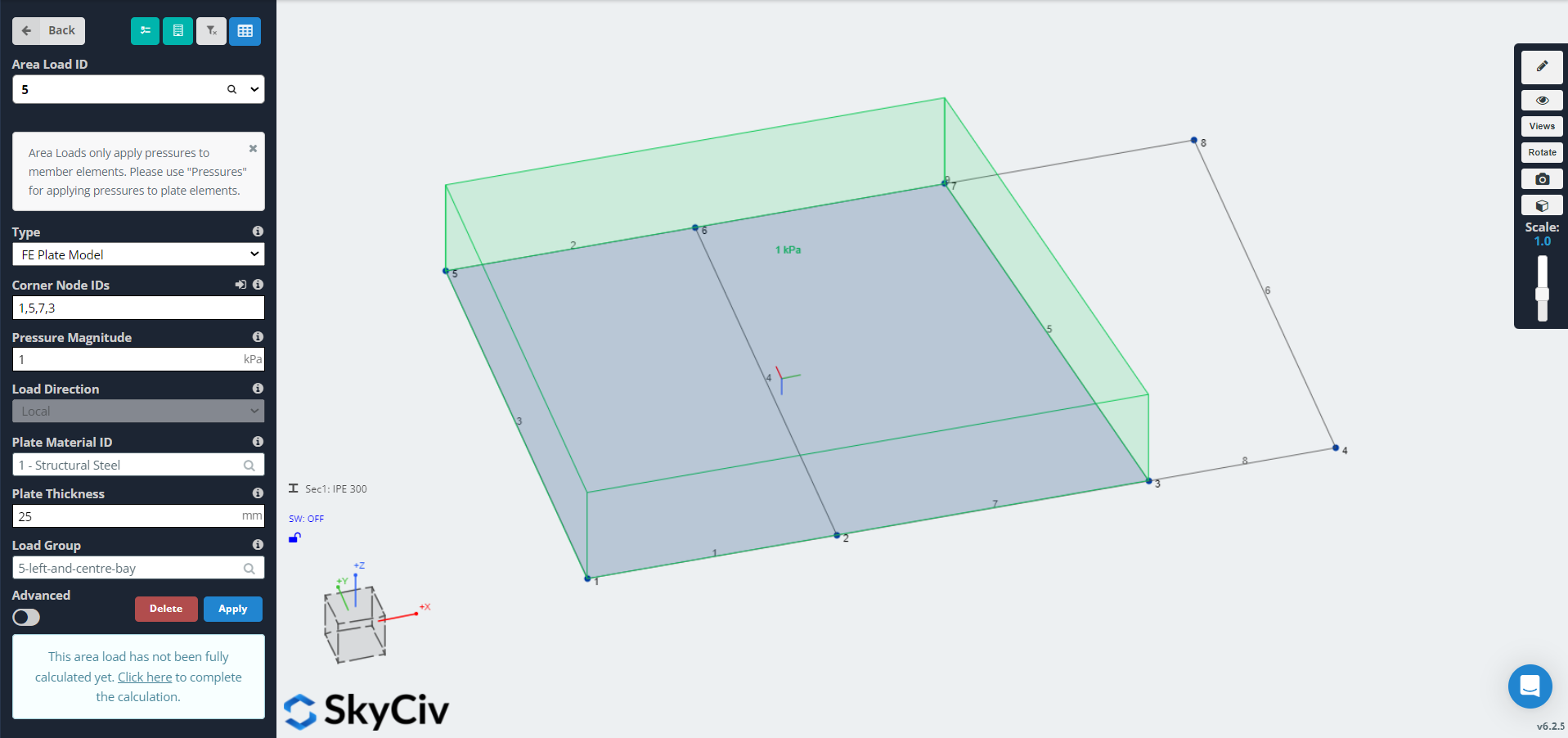
Working with FE Plate Model Area Loads in Structural 3D
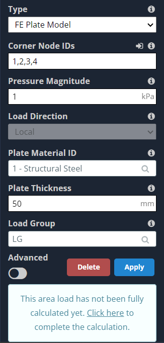
FE Plate Model Area Loads are found under Area Loads, Type = FE Plate Model.
The following inputs are required:
- Corner Node IDs – a list of nodes in the model.
- Nodes must form an enclosed area
- It is not necessary for members to be present on all edges
- Each node must have at least one member attached to it
- Pressure Magnitude
- The pressure to be applied (perpendicular to the area)
- Plate Material ID
- ID of a material in the S3D model, that will be used for the plate in the FE Plate submodel
- Plate Thickness
- Thickness of the plate in the FE Plate submodel
- Load Group
- Name of the load group for this load
Distributing the loads
Unlike other area load types, FE plate model area loads do not distribute automatically during modelling, because FE plate model area loads must run the SkyCiv finite element solver.
FE plate model area loads can be distributed manually by the user:
- For an individual area load, using the button in the left hand menu
- For multiple area loads at a time, from the Check Area Loads Variances
Manual distribution of a single FE plate model area load
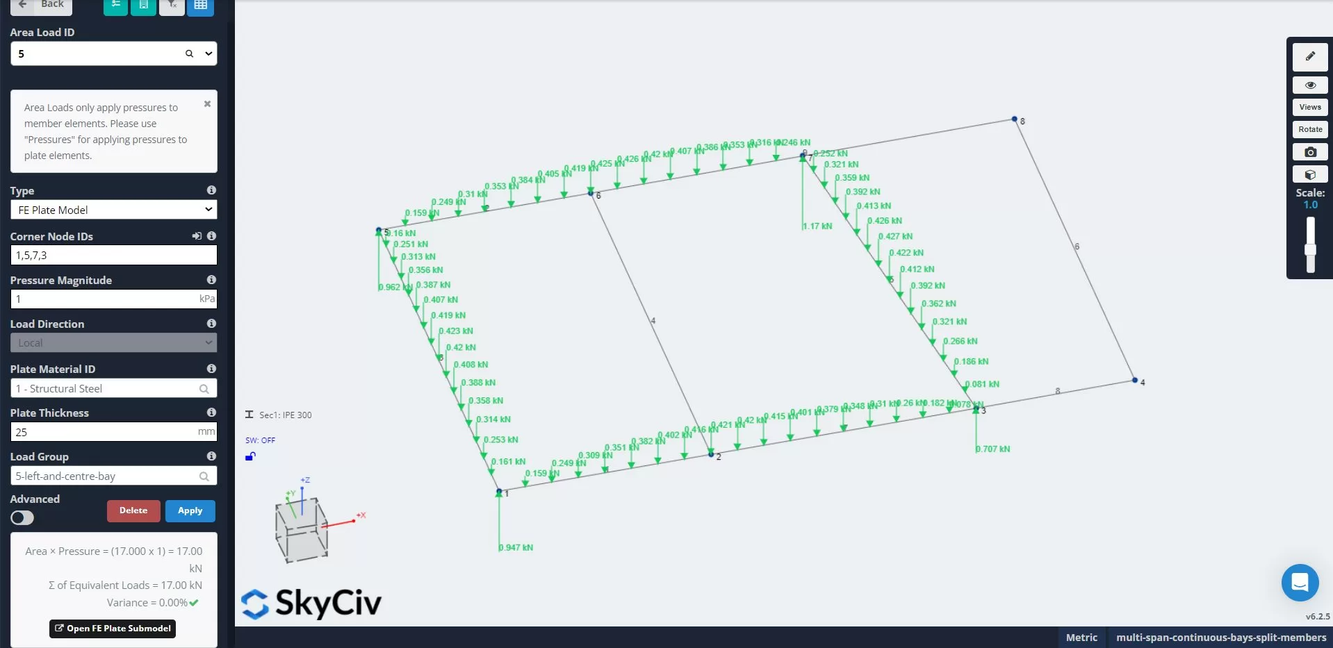
FE plate model area loads can be distributed manually, for an individual area load, using the button in the left hand menu:
Manual distribution of multiple FE plate model area loads
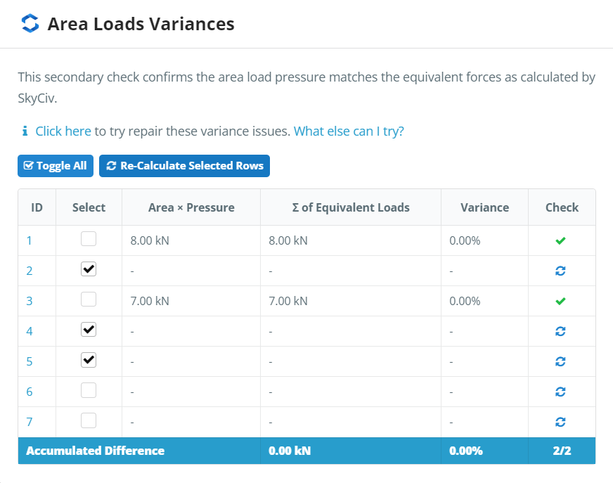
FE plate model area loads can be distributed manually, for multiple area loads at a time, from the Check Area Loads Variances dialog. This dialog can be launched from the Tools menu.:
Select the loads you wish to distribute, and select “Re-calculate Selected Rows”.
Automatic distribution of Fe plate model area loads on solve
Any FE plate model area loads that have not been manually distributed will be automatically distributed when any analysis is run.
Select Solve and then any desired analysis, and the distribution will run automatically.
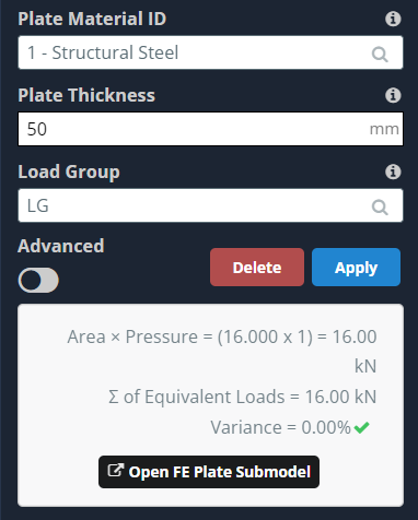
Inputs
FE Plate area loads have various inputs that affect the distribution and resulting equivalent point loads.
Plate Thickness
The plate thickness field sets the thickness of the plate in the FE submodel. Generally, when a lower thickness is used, the loads will distribute to the surrounding members.
When a higher thickness is used, the loads will distribute to the corners of the plate.
In the image below, the left hand area load has a thickness of 3 mm, and the right hand area load has a thickness of 300 mm:
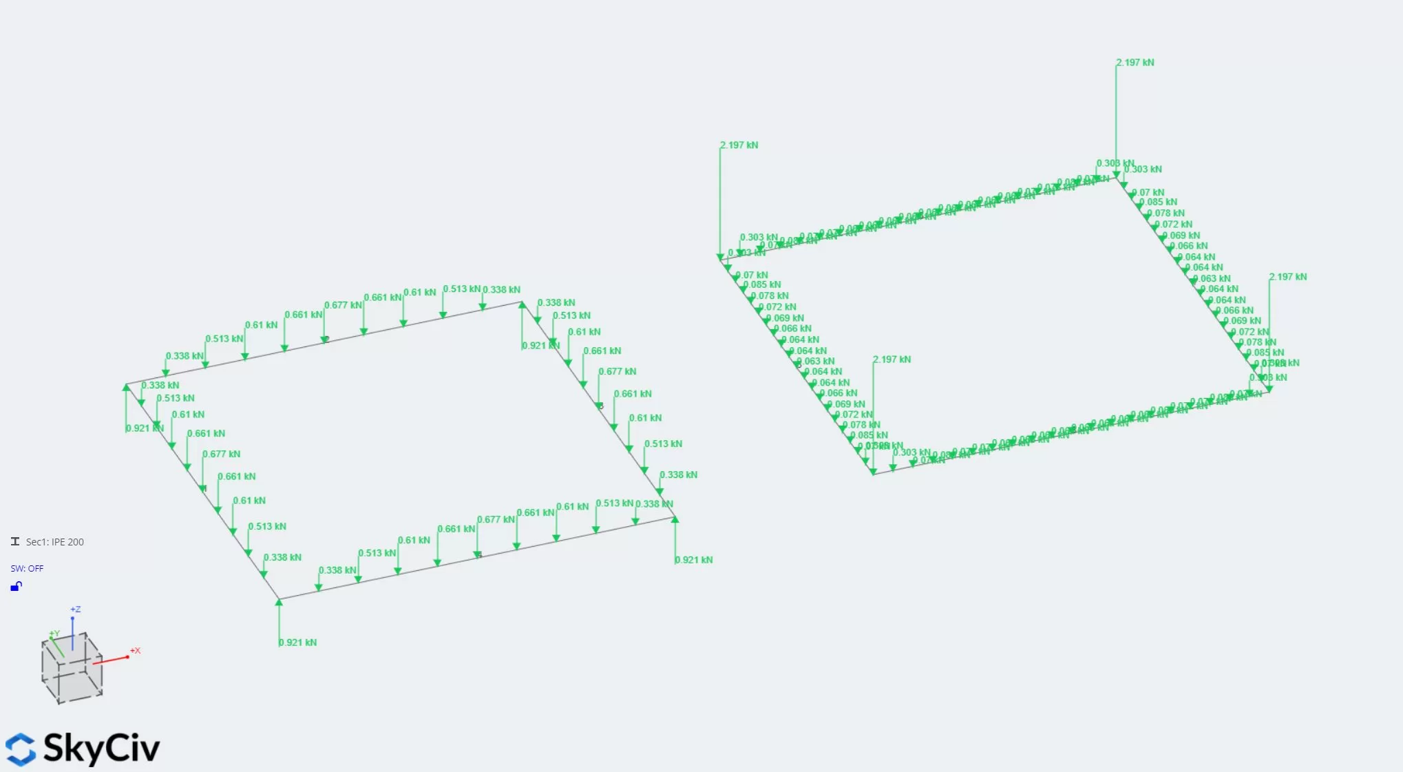
As discussed, it can be seen that the left hand area load, with a lower thickness, has plenty of load over the span of the member. The right hand area load, with a higher thickness has most of the load in the corners.
For discussion of uplift forces at corners, see the section on “impact of plate torsional stiffness on the load distribution”.
Advanced Inputs
Expanding the advanced setting will reveal the following additional input properties:
- Plate Torsional Stiffness – Yes/No
- Whether the plate in the FE plate submodel should have stiffness in torsion
- Plate Axis Rotation – angle in degrees
- The rotation of the plate axes in the FE plate submodel
- Number of Segments
- The number of segments used to divide the members, affecting the mesh size
Plate Torsional Stiffness
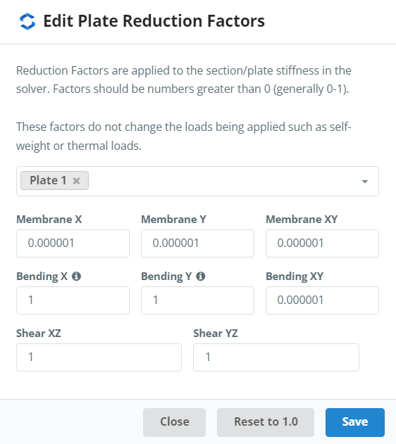
The torsional stiffness of the plate in the FE plate submodel can be enabled or disabled using this option. If “No” is selected, the following reduction factors are applied to the plate in the FE plate submodel:
Impact of the plate torsional stiffness on the load distribution
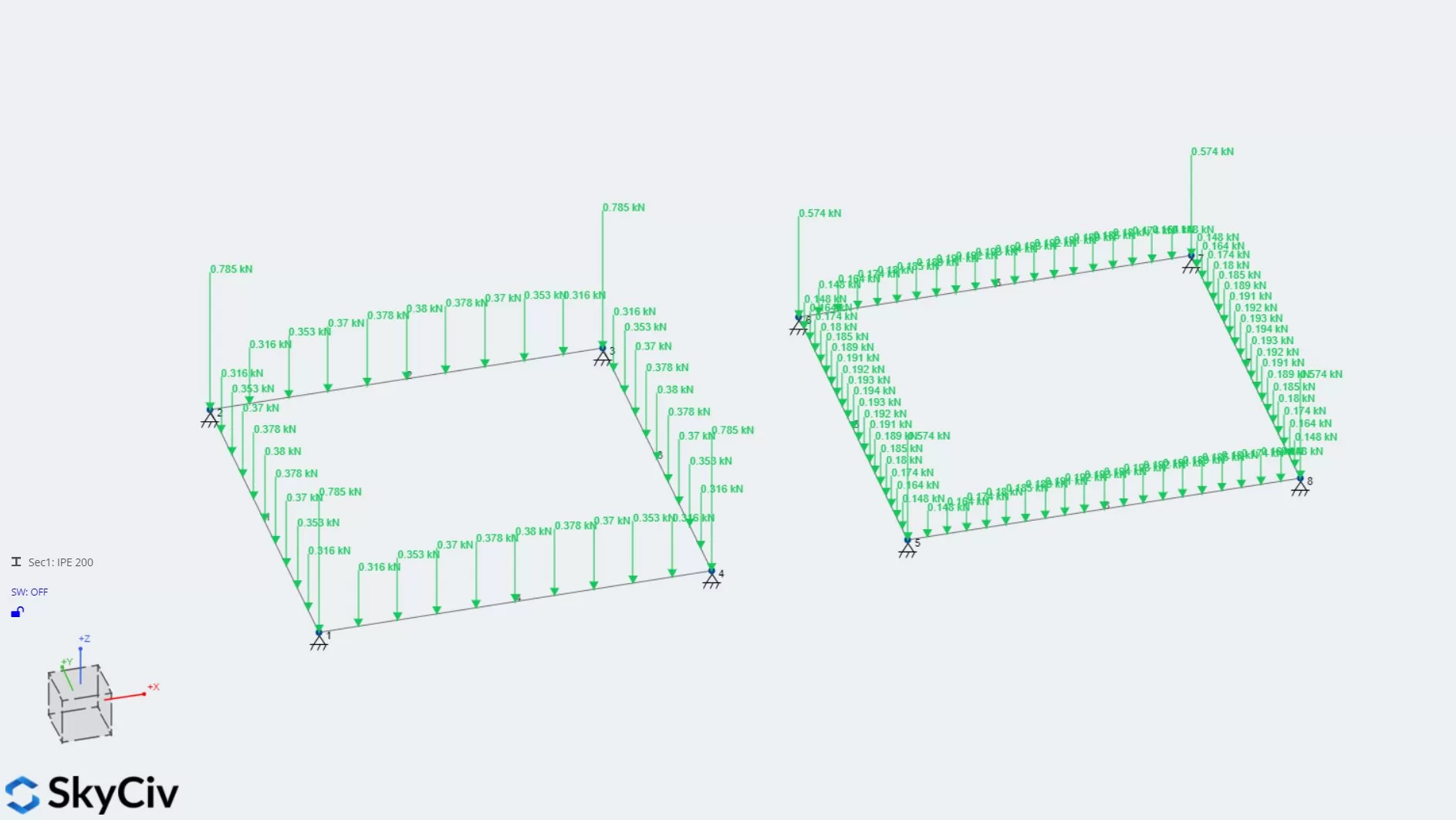
The plate torsional stiffness affects the distribution of the loads, in particular it eliminates the reversed forces at the plate corners. In the following image, area loads are applied to 2 4×4 m squares.
The area load on the left has plate torsional stiffness, the area load on the right does not have plate torsional stiffness.
It can be seen that the load distribution is different – in particular there is no upward force in the corners of the area load on the right, which has no torsional stiffness.
While less precise in theory, this leads to a distribution which is more similar to textbook two-way distributions, which might be preferable to some users.
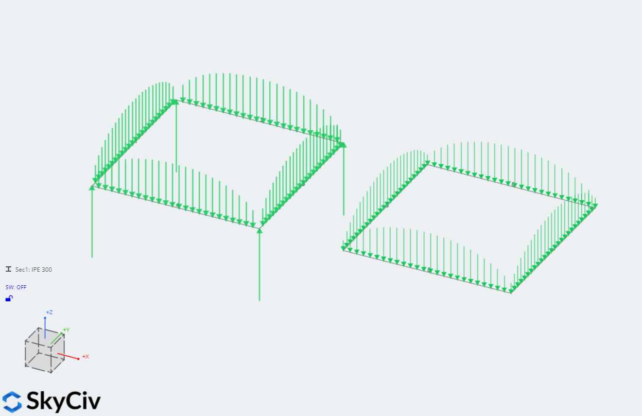
Plate axis rotation
By default, the axis system of the plate in the FE submodel is defined such that the X-axis aligns with the first 2 nodes entered in the Corner Node IDs field.
The plate axis can be modified in the left hand menu and is shown when the area load is selected:
The alignment of the plate axis affects the distribution of the loads in the following ways:
- Loads distribute toward the members along the line of the axes due to the bending stiffness of the plate
- Loads distribute toward the members away from the line of the axes due to the torsional stiffness of the plate
- Thus, where torsional stiffness is omitted (see above section), the plate axis rotation has a greater effect on the distribution of the load
Number of Segments
The number of segments is used to determine the mesh size, by dividing the shortest member length by the number of segments.
A greater number of segments gives a finer mesh, is slower to distribute, and gives more point loads on the resultant distribution.
A smaller number of segments gives a coarser mesh, will distribute faster, and gives fewer resulting point loads.
For example, in the following image, the square on the left is using 10 segments, and the square on the right is using 20 segments:
If the distribution does not look satisfactory, try increasing the number of segments to get a finer distribution.
If the distribution is taking too long, try reducing the number of segments to get the model to solve faster.
Opening the submodel to view the plate FE submodel
Once an FE plate model area load has been distributed, the plate submodel used to perform the distribution can be inspected using the button at the bottom of the left hand menu, when the area load is selected:
Clicking the button will open the FE Plate Submodel in another window.
Warnings and common issues
When distributing the loads, you may see errors or warnings. Some common issues are listed below.
Large displacement error
You may see the following error when trying to distribute FE Plate area loads:

This occurs because the plate is too flexible, and the solver cannot solve the model at all.
Try some or all of the following options to resolve the error:
- use a thicker plate
- use a stiffer plate material
- enable plate torsion
Large displacement warning
A similar warning regarding displacement may be displayed:
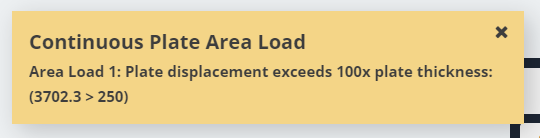
In this case, the plate is very flexible and a large displacement has been observed, but the solver has still managed to solve the model.
You can choose to ignore this warning, or try some or all of the following options to resolve it:
- use a thicker plate
- use a stiffer plate material
- enable plate torsion
Section missing warning
You may see the following warning when trying to distribute FE Plate area loads:
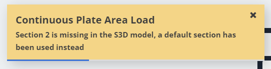
This warning occurs because the section referenced by one of the members bounding the area load does not exist in the main Structural 3D model. In this case, a default section (100 mm x 100 mm, or 4 in x 4 in) will be used instead in the FE Plate area load submodel.
Ensure the referenced section has been chosen in the Sections part of S3D to resolve this warning.
In-plane reaction warning
You may see the following warning when trying to distribute FE Plate area loads:
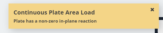
Typically, since the area load is perpendicular to the area it is applied to, all reactions in the area load submodel are perpendicular to the submodel plate.
This warning indicates that reactions in the plane of the plate have been found. This also means there are member shear forces in the plane of the plate.
These in-plane forces are ignored, and only the shear forces and reactions perpendicular to the plate are returned as equivalent point loads.
This occurs because the principal axes of the members bounding the area load are not aligned with the normal axis of the area load. This commonly happens because:
- The bounding members used asymmetric sections, e.g. L shapes
- The bounding members use symmetric sections, but have a rotation that is not a multiple of 90 degrees
To resolve this warning, ensure the two above conditions are not occurring.
Alternatively, you can choose to open the submodel and inspect the pattern of shear forces and reactions, to determine whether these are significant.
Summary
FE Plate area loads offer a way to distribute loads across areas with complex shapes, whilst simulating the behaviour of plates.
Want to give FE Plate area loads a try? Sign up for a 14 day free trial to try S3D and FE Plate area loads!