A fully worked example of Wind Load Calculation for Signs using EN 1991-1-4
In this article, we will be discussing how to calculate the wind loads on signboards using EN 1991-1-4 located in Oxfordshire, United Kingdom. Our references will be the EN 1991-1-4 Action on structures (wind load) and BS EN 1991-1-4 National Annex. We will be using similar data in EN 1991-1-4 Wind Load Calculation Example.
SkyCiv automates the wind speed calculations with a few parameters. Try our Signboard Wind Load Calculator:
Structure Data
In this example, we will use the data below. We will consider only wind source direction equal to 240°. Moreover, the ground elevation of the site is 57.35m.
Table 1. The signboard data that are needed for our wind load calculation.
| Location | Oxfordshire, UK |
| Occupancy | Miscellaneous – Signboard |
| Terrain | Flat farmland |
| Sign Horizontal Dimension, b | 12.0 m |
| Sign Horizontal Vertical, h |
12.0 m |
| Ground to top of signboard, H |
50.0m |
| Ground to signboard centroid, ze |
44.0 m |
| Reference area of signboard Asign |
144.0 sq.m. |
| Pole diameter, d |
1.0 m |
| Pole surface type |
Cast iron |
| Ground to top of pole, zg |
38.0 m |
| Reference area of pole Apole |
38.0 m |
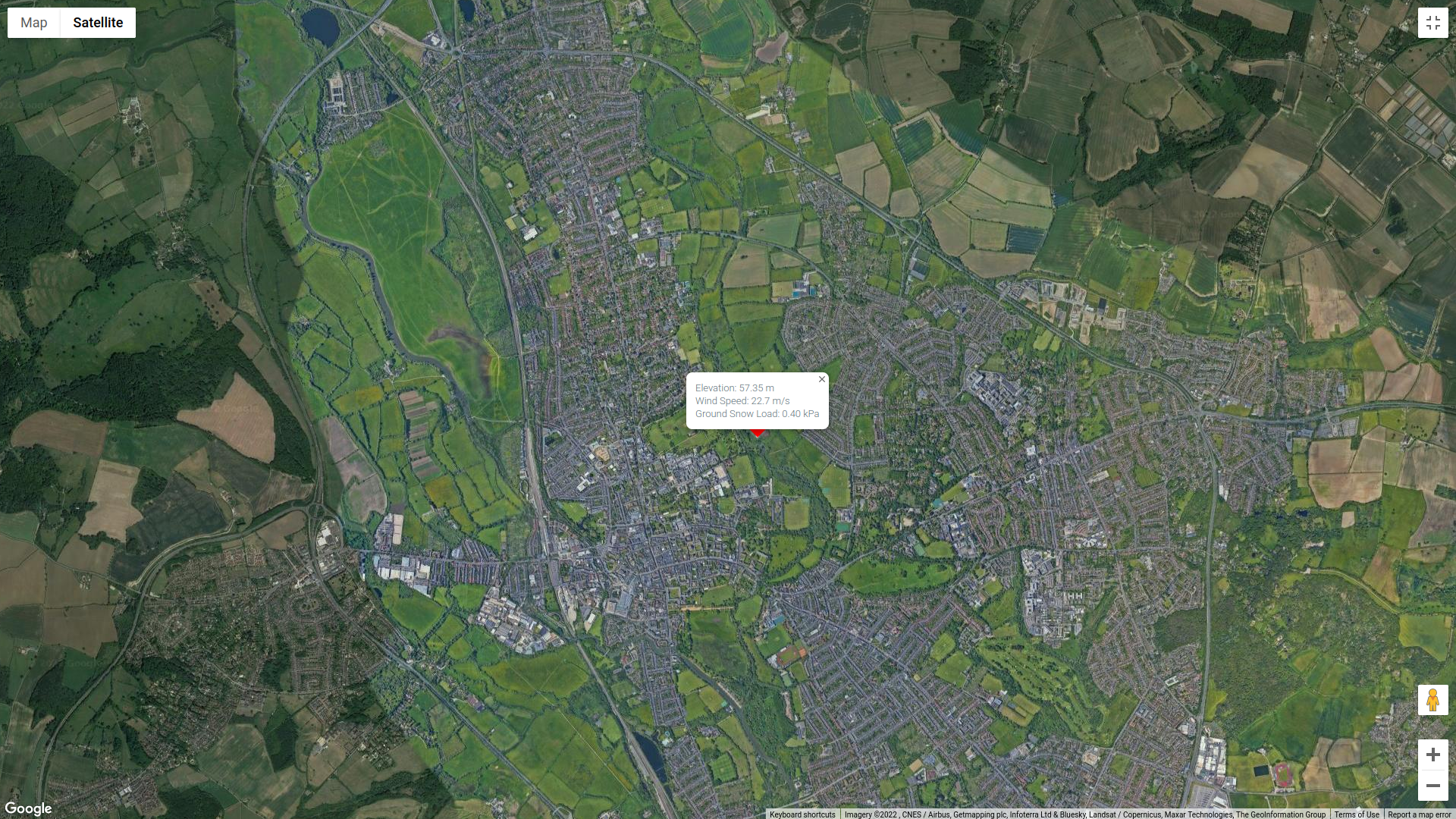
Figure 1. Site location (from Google Maps).

Figure 2. Signboard dimensions.
The formula in determining the design wind pressure are:
For basic wind velocity:
\({v}_{b} = {c}_{dir} {c}_{season} {c}_{alt} {v}_{b,map}\) (1)
Where:
\({v}_{b}\) = basic wind velocity in m/s
\({c}_{dir}\) = directional factor
\({c}_{season}\)= seasonal factor
\({c}_{alt}\)= altitude factor where:
\({c}_{alt} = 1 + 0.001A \) for \( z ≤ 10 \) (2)
\({c}_{alt} = 1 + 0.001A ({10/z}^{0.2}) \) for \( z > 10 \) (3)
\({v}_{b,map}\) = fundamental value of the basic wind velocity given in Figure NA.1 of BS EN 1991-1-4 National Annex
\( A \) = altitude of the site in metres above mean sea level
For basic velocity pressure:
\({q}_{b} = 0.5 {⍴}_{air} {{v}_{b}}^{2} \) (4)
Where:
\({q}_{b}\) = design wind pressure in Pa
\({⍴}_{air}\) = density of air (1.226kg/cu.m.)
\({v}_{b}\)= basic wind velocity in m/s
For peak pressure:
\({q}_{p}(z) = 0.5 {c}_{e}(z){q}_{b} \) for site in Country terrain (5)
\({q}_{p}(z) = 0.5 {c}_{e}(z){c}_{e,T}{q}_{b} \) for site in Town terrain (6)
Where:
\({c}_{e}(z)\) = exposure factor
\({c}_{e,T} \) = exposure correction factor for Town terrain
To calculate the wind force acting on the signboard/pole:
\({F}_{w} = {c}_{s}{c}_{d}{c}_{f}{q}_{p}({z}_{e}){A}_{ref} \) (7)
Where:
\( {c}_{s} {c}_{d} \) = structural factor
\({c}_{f} \) = force coefficient of the structure
\({q}_{p}({z}_{e}) \) = peak velocity pressure at reference height \({z}_{e} \)
\({A}_{ref} = b h\) = reference area of the structure
Terrain Category
Based on BS EN 1991-1-4 National Annex, the Terrain Categories in EN 1991-1-14 were aggregated into 3 categories: Terrain category 0 is referred to as Sea; Terrain categories I and II have been considered as Country terrain, and Terrain categories III and IV have been considered as Town terrain.
Considering wind coming from 240°, we can classify the terrain category of the upwind terrain as Town terrain.
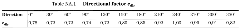
Directional and Season Factors, \({c}_{dir}\) & \({c}_{season}\)
In order to calculate for Equation (1), we need to determine the directional and season factors, \({c}_{dir}\) & \({c}_{season}\). From Table NA.1 of BS EN 1991-1-4 National Annex, since the wind source direction is 240°, the corresponding value for directional factor, \({c}_{dir}\), is equal to 1.0.
On the other hand, we want to consider a conservative case for the season factor, \({c}_{season}\), which we will set to 1.0.
Altitude Factor \({c}_{alt}\)
For the altitude factor, \({c}_{alt}\), we will only use Equation (2) for a more conservative approach using site elevation \( A \) equal to 57.35m. Therefore:
\({c}_{alt} = 1 + 0.001(57.35) = 1.05735\)
Basic Wind Velocity and Pressure, \({v}_{b}\) & \({q}_{b}\)
The wind speed map for the United Kingdom can be taken from Figure NA.1 of the National Annex for BS EN 1991-1-4.
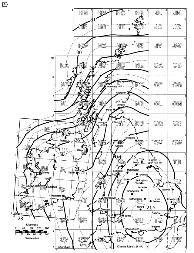
Figure 5. Basic wind speed for United Kingdom based on Figure NA.1 of BS EN 1991-1-4 National Annex.
For our site location, Oxfordshire, England, the calculated \( {v}_{b,map} \) is equal to 22.7 m/s.
\( {v}_{b} = {c}_{dir} {c}_{season} {c}_{alt} {v}_{b,map} = (1.0)(1.0)(1.05735)(22.7) \)
\( {v}_{b} = 24.0 m/s \)
We can calculate the basic wind pressure, \( {q}_{b,0} \), using Equations (4):
\( {q}_{b} = 0.5(1.226)({24}^{2}) = 353.09 Pa \)
SkyCiv now automates detection of wind region and getting the corresponding wind speed value with just a few input. Try our SkyCiv Free Wind Tool
Orography Factor \({c}_{o}(z)\)
For this structure, the terrain is relatively flat for the wind coming from 240°, the
altitude factor, \({c}_{alt}\), we will only use Equation (2) for a more conservative approach using site elevation \( A \) equal to 57.35m. Therefore:
Peak Velocity Pressure, \({q}_{p}(z)\)
For our structure, since the terrain category is classified as Town terrain, the peak Similarly, the peak velocity pressure, \({q}_{p}(z)\), can be solved using Equation (6):
\({q}_{p}(z) = {c}_{e}(z){c}_{e,T}{q}_{b} \)
Where:
\({c}_{e}(z)\) = exposure factor based on Figure NA.7 of BS EN 1991-1-4 National Annex
\({c}_{e,T} \) = exposure correction factor for Town terrain based on Figure NA.8 of BS EN 1991-1-4 National Annex
To determine the exposure factor, \({c}_{e}(z)\) , for the signboard, we need to calculate the \(z – {h}_{dis}\) and the distance upwind to shoreline in km. For simplicity, we will set the the displacement height, \({h}_{dis}\), to 0. For the \(z \) values, we will consider it on \(z = 38.0\) and \(z = 44.0\). Moreover, the distance upwind to shoreline is more than 100km. Therefore, using Figure NA.7 of BS EN 1991-1-4 National Annex:
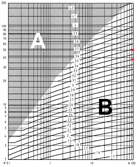
Figure 6. Figure NA.7 of BS EN 1991-1-4 National Annex.
Therefore:
\({c}_{e}(38.0) = 3.2\)
\({c}_{e}(44.0) = 3.3\)
On the other hand, the exposure correction factor \( {c}_{e,T} \) for the signboard can be determined from Figure NA.8 of BS EN 1991-1-4 National Annex. Using distance inside town terrain equal to 1km, we can get the exposure correction factor \( {c}_{e,T} \):

Figure 7. Figure NA.8 of BS EN 1991-1-4 National Annex.
Therefore:
\({c}_{e,T}(38.0) = 1.0\)
\({c}_{e,T}(44.0) = 1.0\)
Using the values above, we can calculate the peak velocity pressure, \({q}_{p}(z)\), for \(z = 38.0\) and \(z = 50.0\):
\({q}_{p}(44.0) = (3.3)(1.0)(353.09) = 1165.20 Pa \)
\({q}_{p}(38.0) = (3.2)(1.0)(353.09) = 1129.89 Pa \)
Structural Factor, \( {c}_{s}{c}_{d} \)
For our signboard, we will use simplified value for the structural factor, \({c}_{s}{c}_{d}\), to be equal to 1.0 based on Section 6 of EN 1991-1-4.
Force Coefficient, \( {c}_{f}\), for signboard
For signboards, the force coefficient, \({c}_{f}\), is equal to 1.8 based on Section 7.4.3 of EN 1991-1-4.
Wind Force, \( {F}_{w,signboard} \), acting on the signboard
The force acting on the signboard can be calculated using Equation (7) based on Section 5.3(2) of EN 1991-1-4.
\({F}_{w,signboard} = {c}_{s}{c}_{d}{c}_{f}{q}_{p}({z}_{e}){A}_{ref,signboard} = (1.0)(1.8)(1165.20Pa)(12.0m)(12.0m)\)
\({F}_{w,signboard} = 302019.84 N\)
Note that the horizontal eccentricity of this wind force acting on the centroid of the signboard is recommended to be equal to 3.0m.
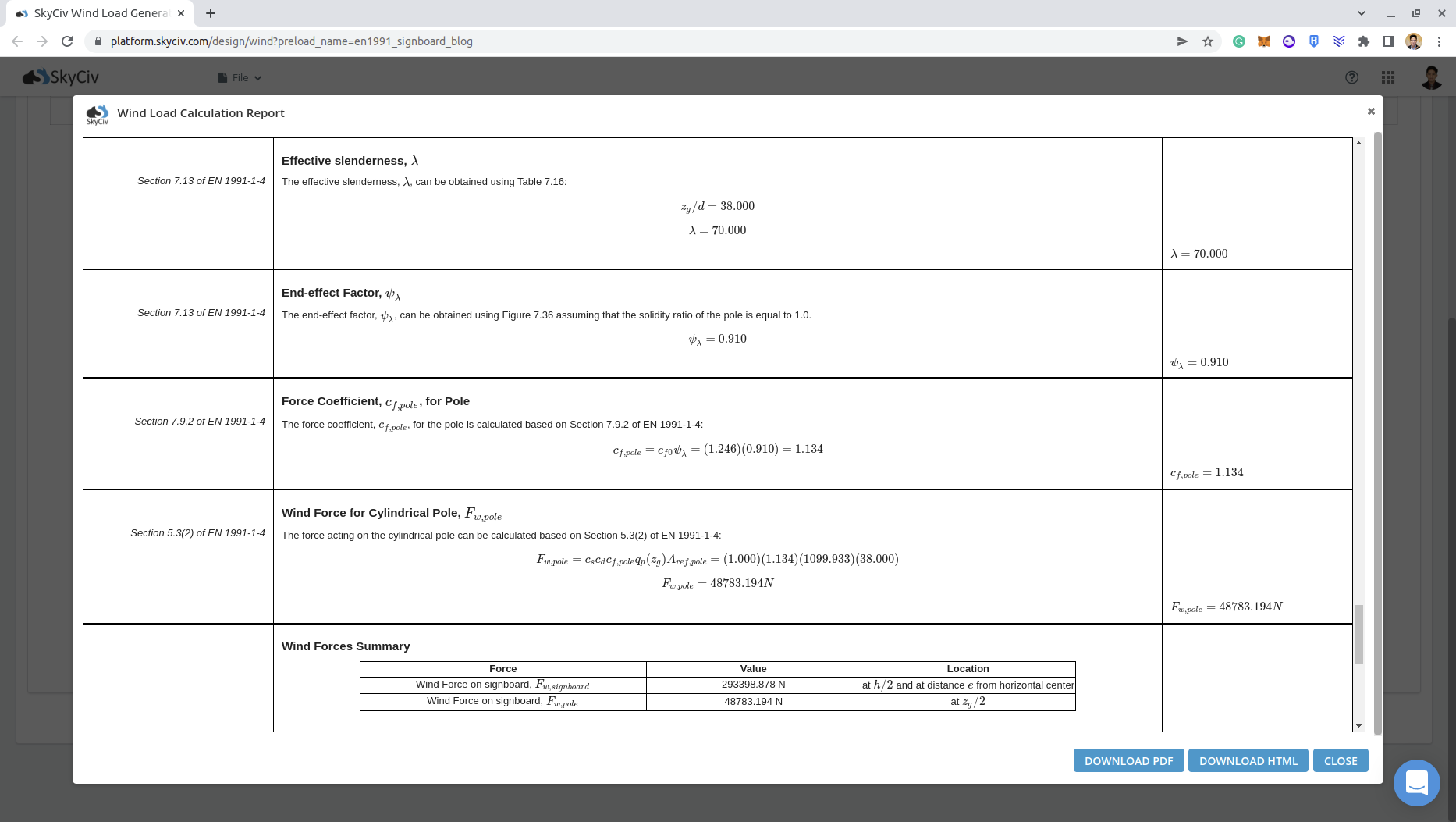
The wind calculations can all be performed using SkyCiv Load Generator for EN 1991 (signboard and pole wind load calculator). Users can enter the site location to get the wind speed and terrain data, enter the solar panel parameters and generate the design wind pressures. With the standalone version, you can streamline this process and get a detailed wind load calculation report for signboards and poles!
Wind Force, \( {F}_{w,pole} \), acting on the pole
Similarly, the force acting on the pole can be calculated using Equation (7) based on Section 5.3(2) of EN 1991-1-4.
\({F}_{w,pole} = {c}_{s}{c}_{d}{c}_{f}{q}_{p}({z}_{g}){A}_{ref,pole}\) (8)
Where:
\({c}_{f} = {c}_{f,0}{ψ}_{λ} \)
\({A}_{ref,pole} = {z}_{g}d \)
Note:
\(ψ_{λ} \) is calculated based on effective slenderness, \( λ \), using using Figure 7.36 of Section 7.13 of EN 1991-1-4
\({c}_{f,0}\) is calculated based on Reynolds number \( R_{e} \) using Figure 7.28 of EN 1991-1-4
Where:
\( {z}_{g} \) is the height of the pole from the ground in m
\( d \) is the diameter of the pole in m
\( ν = 0.000015 sq.m/s \) is the kinematic viscosity of the air
\( v({z}_{g}) = (2{q}_{p}({z}_{g})/ρ)^{0.5} \) (9)
\( {R}_{e} = v(z_{g})d/ ν \) (10)
We will dive deep into these parameters on the next sections
Reynolds number, \( {R}_{e} \), for the pole
Using the calculated values above, we can calculate \( v({z}_{g}) \) using Equation (9):
\( v({z}_{g}) = (2{q}_{p}({z}_{g})/ρ)^{0.5} = (2(1129.89)/(1.226))^{0.5} \)
\( v({z}_{g}) = 42.93 m/s\)
Therefore, the Reynolds number \( R_{e} \) for the pole, using Equation (10) is:
\( {R}_{e} = v({z}_{g})d/ ν = (42.93)(1.0)/(0.000015) \)
\( {R}_{e} = 2862000 \)
Force coefficient, \( {c}_{f0} \), without free-end flow
The pole material we used is cast-iron which has equivalent surface roughness \( k \) equal to 0.2 based on Table 7.13 of EN 1991-1-4.
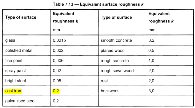
Figure 8. Table 7.13 of EN 1991-1-4 for Equivalent roughness \( k \).
The force coefficient \( {c}_{f0} \) can be determined using the formula from Figure 7.28 of of EN 1991-1-4 with \( k/d = 0.2\):
\( {c}_{f0}= 1.2 + {0.18log(10 k/d)}/{1 + 0.4log({R}_{e}/{10}^{6}} = 1.2 + {0.18log(10 (0.2)}/{1 + 0.4log((2862000)/{10}^{6}}\)
\( {c}_{f0} = 1.246 \)
Effective Slenderness, \( λ \)
The effective slenderness, \( λ \), for the pole can be determined from No.4 Table 7.16 of EN 1991-1-4.
\( λ = max(0.7 {z}_{g}/d, 70) \) for \( {z}_{g} \) > 50m
\( λ = max({z}_{g}/d, 70) \) for \( {z}_{g} \) < 15m
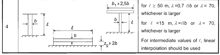
Figure 9. Table 7.16 of EN 1991-1-4 for calculating Effective Slenderness \( λ \).
Since \( {z}_{g} \) is equal to 38.0m, we need to interpolate the values of \( λ \) for 50m and 15m:
\( {z}_{g} = 38\)
\( {λ}_{50m} = max(0.7 (38), 70) = 70 \)
\( {λ}_{15m} = max((38), 70) = 70 \)
Therefore:
\( λ = 70 \)
End-effect Factor, \( {ψ}_{λ} \)
The end-effect factor, \( {ψ}_{λ} \), can be obtained using Figure 7.36 of EN 1991-1-4 requiring the solidity ratio \( φ \) and effective slenderness \( λ \). We will assume solidity ratio \( φ \) equal to 1.0 since the pipe column does not have any perforation.
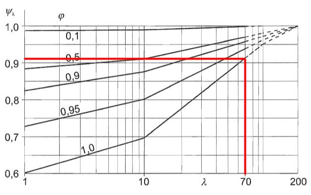
Figure 10. The corresponding end-effect factor \( {ψ}_{λ} \) for the pole supporting the signboard based on Figure 7.36 of EN 1991-1-4.
From Figure 10, we can deduce that the end-effect factor \( {ψ}_{λ} \) for the pole is equal to 0.910.
From the calculated parameters above,we can already calculate the Wind Force, \( {F}_{w,pole} \):
\({c}_{f} = {c}_{f,0}{ψ}_{λ} = (1.246)(0.910) = 1.134\)
\({F}_{w,pole} = {c}_{s}{c}_{d}{c}_{f}{q}_{p}({z}_{e}){A}_{ref,pole} = (1.0)(1.134)(1129.89)(38.0×1.0) \)
\({F}_{w,pole} = 48689.22 N \)
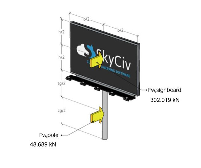
Figure 11. The wind forces acting on the signboard and pole.
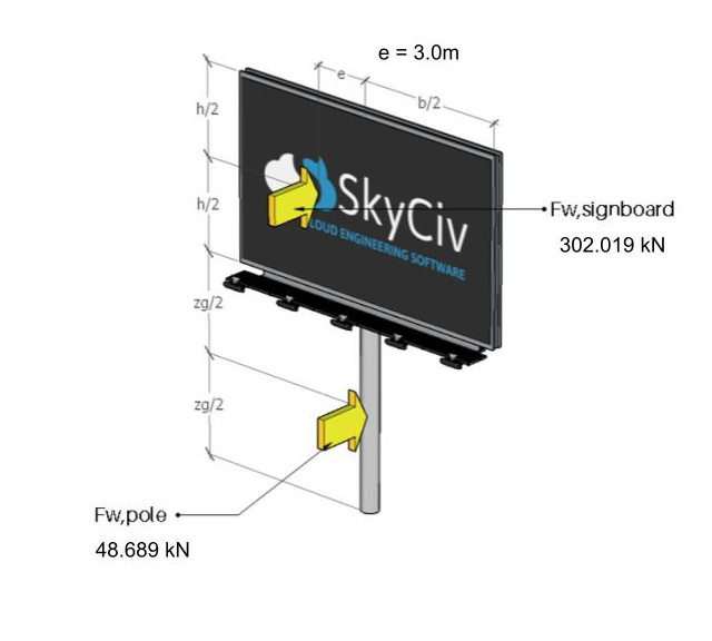
Figure 12. The wind forces acting on the signboard and pole for eccentric case.
SkyCiv Load Generator
Using the SkyCiv Load Generator, you can get wind loads for signboards and poles with just a few clicks and inputs. When you purchase the standalone version or signup for Professional account, you will be able to generate the detailed wind report for your signboard project!

You can check the detailed wind load report for the signboard thru these links:

Structural Engineer, Product Development
MS Civil Engineering
References:
- En, B. (2005). Eurocode 1: Actions on Structures—Part 1–4: General Actions—Wind Actions.
- BSI. (2005). BS EN 1991-1-4: 2005+ A1: 2010: Eurocode 1. Actions on structures. General actions. Wind actions.