Moment Sign Conventions
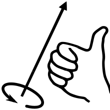
Applied loads, displacements, and reactions are positive when they act along or about the positive axis direction. For rotations (like moments) the positive direction is with respect to the RIGHT-HAND RULE:
Be wary of the axes which are used to define loads. By default, loads are along the global axes however distributed loads can be defined with respect to the local member axis. Similarly, plate pressures can be defined globally or locally to the plate. Also, remember that the local axes of members and plates can be viewed and toggled from the Visibility Settings.
Member Actions
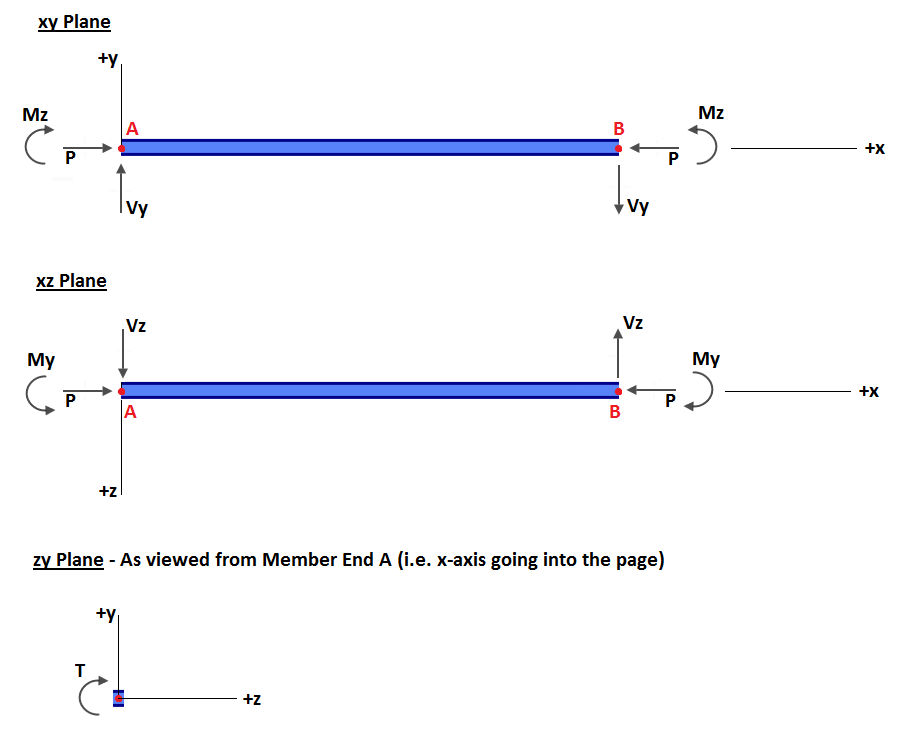
In the diagram above:
- P = Axial Force
- T = Torsional Force (i.e. moment about member’s x-axis)
- Vy = Shear Force in member’s y-axis
- Vz = Shear Force in member’s z-axis
- My = Bending Moment in member’s y-axis
- Mz = Bending Moment in member’s z-axis
The diagram above can be summarized as follows:
- Positive Axial Force (P): Compression
- Positive Moment (M): Compression on the positive axis side of the member
- Positive Shear (V): Node A of the member translates in the positive axis with respect to Node B.
- Positive Torsion (T): Node B rotates clockwise when viewed from the Node A end. Or Node A of the member rotates counter-clockwise when viewed from the Node B end. Both instances conform to the right-hand rule.
NOTE: There is a setting in Settings called “Reverse BMD Sign” which reverses the sign convention of the bending moment diagrams to suit whichever convention you’re most familiar with. You can find this by going to the top toolbar and then Settings > View > Reverse BMD Sign.
Simple Example
By default, a simple downward distributed load with two-point loads will display the following bending moment diagram:
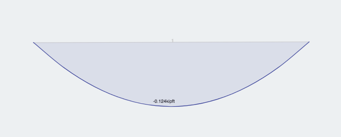
If the ‘Reverse BMD Sign’ setting is toggled on, the exact same model would produce the following bending moment diagram:
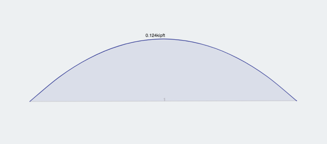
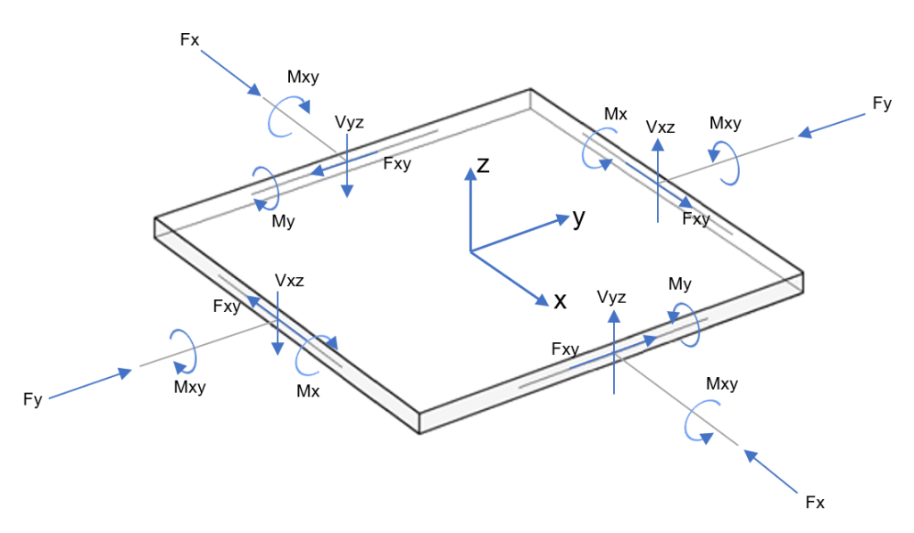
Plate Actions
SkyCiv uses a finite element plate for bending analysis in two principal directions. The plate actions are shown in the following images.
