Load Combinations are used to linearly combine multiple load Groups in various building standards. Each load group within a load combination is multiplied by a Load Factor or Coefficient, which adjusts the weighting of each Load Group. The Load Combinations and their associated Load Factors are described in the various building standards, for example, in ASCE-7 in the United States.
Managing Load Combinations
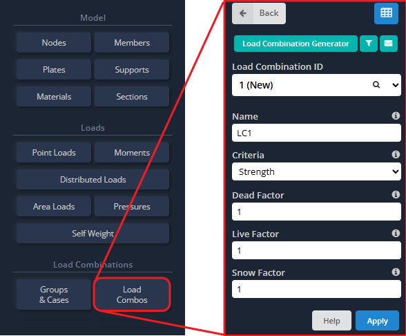
To start, Load Combinations can be added by clicking the Load Combos button within the left menu as shown below. You cannot add a Load Factor> to Load Groups that do not exist yet, so if you are looking to create new load groups, have a look at our video on Load Groups and our video on Load Combinations.
Generating Load Combinations from Building Standards
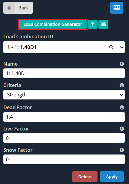
Users can generate Load Combinations from a variety of building standards from across the globe – including the United States (US), Australia, Europe, Canada and India. To get started, click on the Load Combination Generator button while in the Load Combos menu, as shown in the image below.
 Setup Tab
 Setup Tab
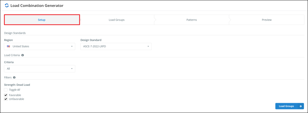
In the Setup tab, you define the Region and Standard to be used to fetch the appropriate load cases and Load Combinations Schema (the Schema is the blueprint for Load Combination generation). Next, the Criteria and Filter sections allow filtering of the generated load combinations. For example, selecting a Criteria of “Strength” and checking “Unfavorable” dead loads only, the Load Combination Generator will ignore all “Serviceability” Load Combinations and those with “Favorable” Dead Load coefficients.
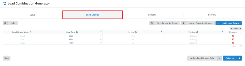
Load Groups Tab
In the Load Groups Tab, you can manage (add, edit or remove) (add, edit or delete). You can also assign Load Cases to Load Groups by selecting the appropriate Load Case in the dropdown menu. If you find yourself often using the same Load Groups (and associated Load Cases) in multiple projects, you can also save and import favorite groups by using the Save Favorite Group / Import Favorite Group buttons.
Patterns Tab
In the Patterns Tab, the number of distinct Load Groups associated to each Load Case is added up and summarized.
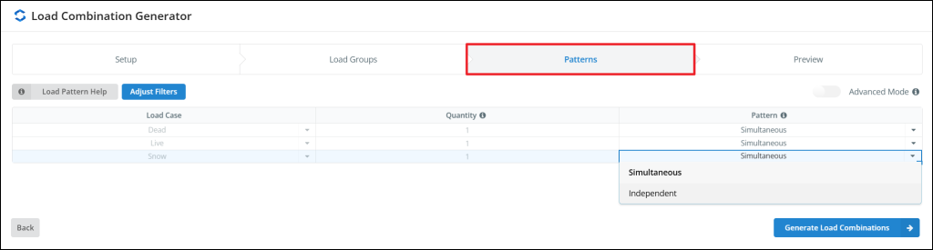
The pattern to use for each load case can be defined in the Pattern column of the table. Patterns are instructions about how to deal with multiple Load Groups assigned to a single Load Case. By default, only two patterns are available:
- Simultaneous Pattern: Generates a single load combination incorporating all load groups — suitable when load groups act simultaneously.
- Independent Pattern: Creates a separate load combination for each load group — ideal for scenarios where load groups act independently (e.g., wind loads from different directions).
 Under the advanced settings, we find two additional patterns:
- Mirror Pattern: Similar to the individual load pattern, but with an additional load reversal (every combination is copied and the coefficient is set to negative to simulate a load acting in both directions).
- Paired Pattern: Allows pairing of two adjacent load groups, applying the main and alternate ratios to both sequentially. Thus, loading can be applied to two directions simultaneously (say 100% in one direction and 30% in the other direction). Useful for wind and seismic loads.
Preview Tab
In the Preview Tab, we get to preview the Load Combinations before they are imported into the Load Combinations Datasheet.
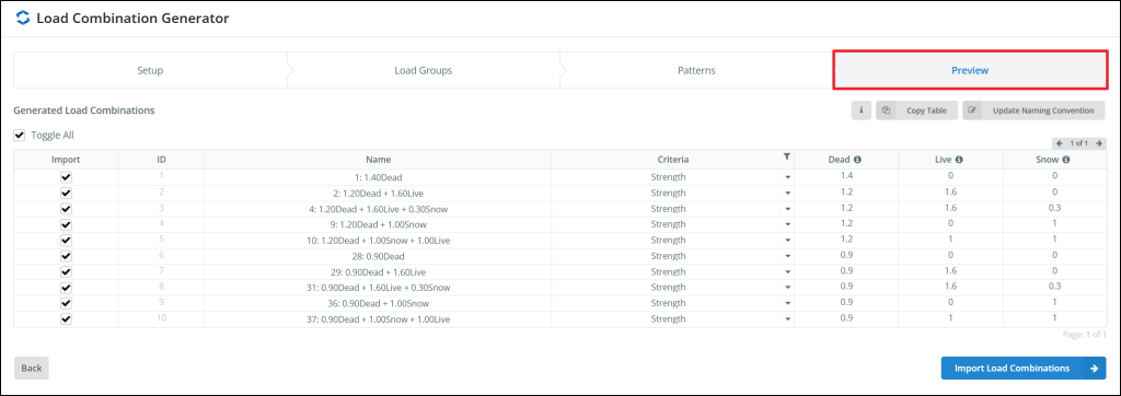
After the Load Combinations are generated, all of the unnecessary ones are automatically removed. The unnecessary Load Combinations can fall into these categories:
- Filtered by Criteria: Self-explanatory, only the Load Combinations associated with the criteria selected in the dropdown are kept. This is defined in the Setup Tab.
- Filtered by sub-filter: Sub-filters are standard dependent. They can be used to select a subset of the Load Combinations. These are defined in the Setup Tab.
- Redundant Load Combinations: When some Load Cases are not present in the model, it will often cause multiple distinct Load Combinations to collapse into identical Load Combinations. These are automatically removed as Redundant Load Combinations.
If you want to see a list of which Load Combinations have been removed, click on the Information button above the table. If you want to copy the table to the clipboard, press the Copy Table button. If you want to update the naming convention Load Combinations, press the Update Naming Convention button.
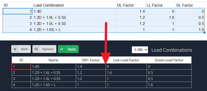
Importing Load Combinations from a Spreadsheet
Sometimes, users will have a compilation of Load Combinations stored in a 3rd party spreadsheet application (like Excel). Instead of importing the Load Combinations from the design codes or inputting them each time, users can simply Copy and Paste their Load Combinations from any other spreadsheet software. Simply use the Copy and Paste commands to copy and paste the Load Combinations into the Load Combinations Datasheet in S3D. Note: Before copy and pasting, make sure the columns are in the same order in the 3rd party spreadsheet as shown in S3D. After pasting into the Datasheet, make sure to hit Apply so that the load combinations are properly saved.
Envelope Load Combinations
Along with your user-defined (or imported) Load Combinations, users can define custom envelopes containing specific load combinations/cases/groups to make it easier to review the results. The Custom Load Combination Envelopes will display the absolute worst case result for each member and compile them into one neat set of results. For instance, for an envelope containing all Load Combinations, say member 1’s worst shear case is 1.4D – the Envelope Case will display that result for member 1.
Defining Custom Envelopes
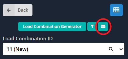
Custom envelopes can be defined from the Load Combos menu by clicking the green Envelope button at the top of the menu. This will open up the Customize Envelope Load Combinations menu.
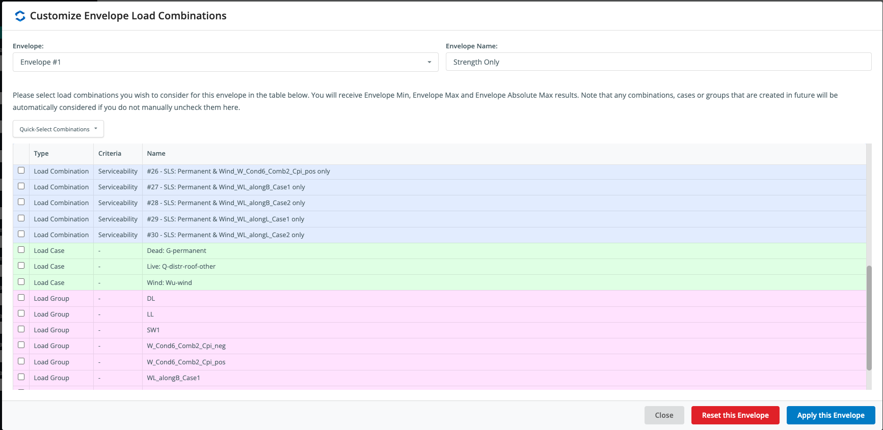
You can define up to three custom envelopes. Custom envelopes can be set through the following steps:
- Select the envelope you wish to modify from the Envelope dropdown.
- Assign a name to the envelope in the Envelope Name input box.
- Scroll through and select from the list of Load Combinations/Load Cases/Load Groups that you would like to include within the envelope. A tick means the load combination will be included, unticked means it will be excluded from the envelope.
- Click Apply this Envelope at the bottom right of the window to apply the specific envelope.
Note: You must click Apply this Envelope for each individual envelope you modify. Any changes made to an envelope without clicking this button will be lost when the menu is closed.
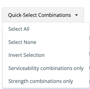
You can quickly filter the Load Combinations to be included in the envelope using the Quick-Select Combinations dropdown. Serviceability and Strength Load Combinations will be selected based on the design criteria assigned to each individual Load Combination.
By default the software, the software will add the following envelope cases containing all load combinations:
- Envelope Min – Load combination with the minimum peak results (i.e. negative results)
- Envelope Max – Load combination with the maximum peak results (i.e. positive results)
- Envelope Absolute Max – Will take the absolute maximum of the above two results
Each custom envelope defined will also be available with a Min, Max and Absolute Max result.
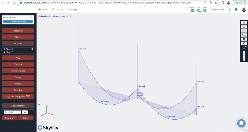
These results can also be displayed alongside each other, and other load combinations to compare and contrast results. Below, we are comparing both the Envelope Min vs Envelope Max load combinations:
Reviewing Load Combinations Results
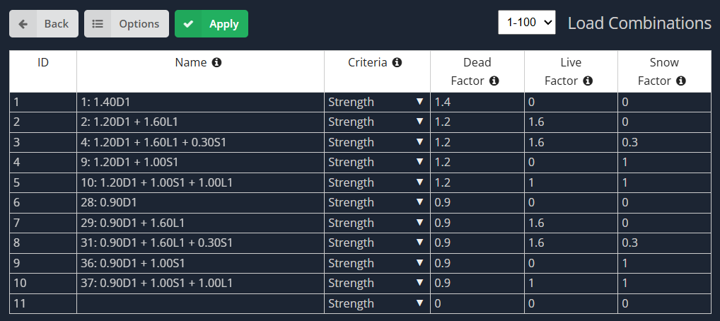
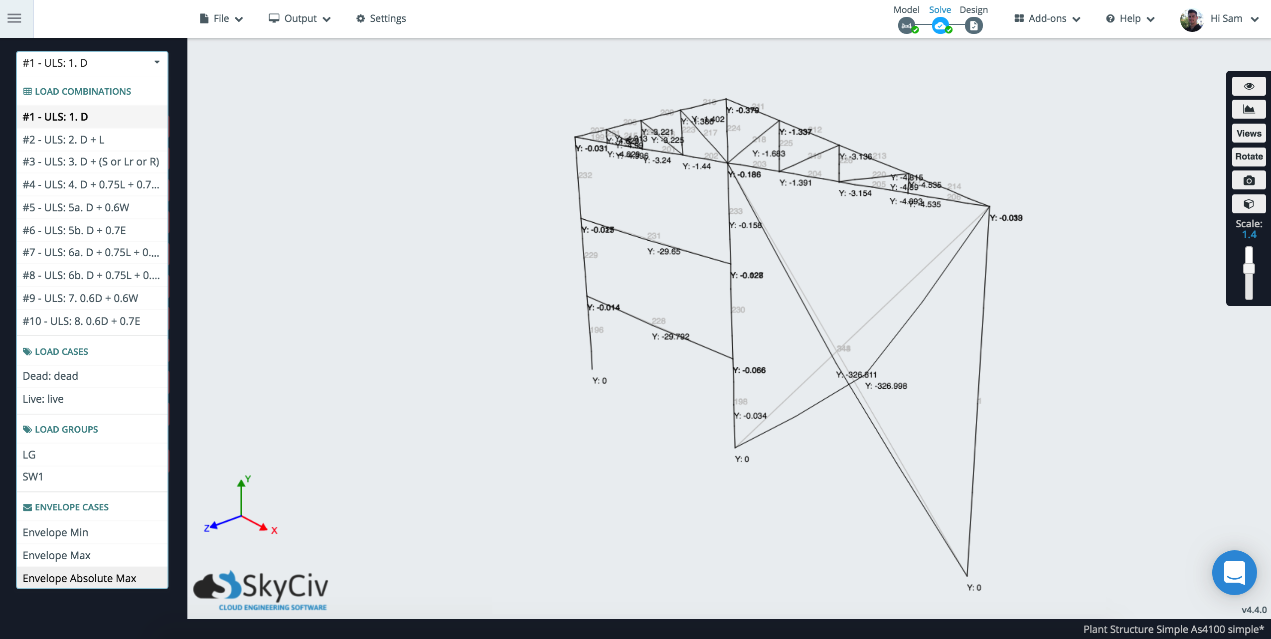
Once solved, your Load Combinations, load cases and envelope load combinations will be available on the left menu. Here is a sample of some of the load combinations you might expect to see returned from the solver:
Load Combination Settings
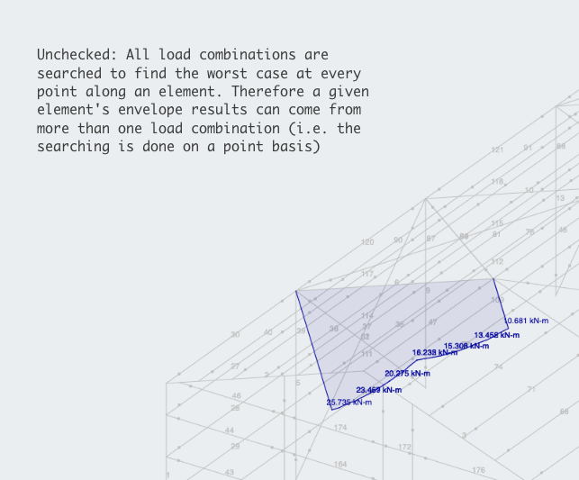
Users can control certain Load Combination Settings, under Settings – Solver – Use Alternate Envelope Method. The following envelope results will display based on this checkbox:
Use Alternate Envelope Method:
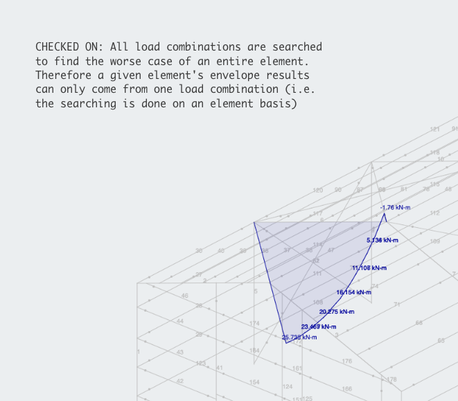
Use Alternate Envelope Method:
Other settings include which load groups/cases are solved. By default these are all solved, but to save unnecessary solving time users can ignore certain load groups/cases if they are not required: