Cold-formed steel member design is challenging due to the complex stability behavior of the thin-walled members. To address this problem several methods have been developed, like the Direct Strength Method (DSM), the most flexible and modern approach. SkyCiv is committed to help supporting DSM, through resources such as this and software that supports cold formed steel design through this approach.
The DSM provides predictions of cold-formed member strength without calculating effective widths [1] (effective widths calculation is often a complex process with many limitations to analyze complex geometric shapes). In this method, the calculation of critical buckling strength can be carried out in various approaches, mainly the Finite Strip Method (FSM) and the Finite Element Method (FEM). In this guide, we will explore:
- What is the Direct Strength Method
- Acceptance and Adoption in the Industry
- Conventional Finite Strip Method
- Buckling Mode Types
- What are the DSM Factors?
- Finite Strip Method in SkyCiv Section Builder
Watch Our Tutorial on Calculating Direct Strength Method Factors
What is the Direct Strength Method (DSM)
The Direct Strength Method (DSM) is a design approach used predominately for the analysis and design of cold-formed steel members. Unlike traditional methods (such as the Effective Width Method) that rely on calculating effective section properties to account for local buckling, the DSM directly computes the member’s strength using its full, unreduced cross-sectional properties.
Pros and Cons of Direct Strength Method
| Pros | Cons |
|---|---|
| Simplifies Design Process: Reduces complexity by eliminating effective width calculations. | Learning Curve: Requires engineers to become familiar with new concepts and formulations. |
| Enhanced Accuracy: Directly accounts for various buckling modes for precise strength predictions. | Limited Historical Data: Less empirical data available for some specific applications compared to traditional methods. |
| Versatile Application: Suitable for complex and unconventional cross-sections. | Software Dependence: May require advanced software tools not readily available to all practitioners. |
| Unified Methodology: Provides a consistent approach across different buckling behaviors. | Standard Compliance: Not all regional codes may fully incorporate DSM provisions yet. |
| Facilitates Innovation: Encourages the use of new materials and shapes due to its adaptable framework. | Resistance to Change: Industry inertia can slow adoption as practitioners stick to familiar methods. |
Adoption and Acceptance:
The DSM is recognized and incorporated into major international design standards, such as:
- AISI S100: North American Specification for the Design of Cold-Formed Steel Structural Members.
- AS/NZS 4600: Australian/New Zealand Standard for Cold-Formed Steel Structures.
DSM is also being prioritised as a future method by being taught in universities and becoming a more common method taught in cold formed design courses. We’re also seeing an increase in it’s support by structural analysis and design software packages who are integrating DSM into their design modules.
However, there are still some obstacles and challenges in the DSM being widely-adopted, since it is a relatively new/untaught method. Transitioning from traditional methods requires training and adaptation, which some practitioners can be reluctant to undertake.
Conventional Finite Strip Method
The FSM was created as a simplification of the FEM, both methods have the same theoretical background, and the FSM is also a matrix method. By defining the nodes and elements of a section it is possible to analyze any complex shape. This encourages section optimization and simplifies the analysis process.
Several options, including open-source tools, are currently available to perform Finite Strip analysis. However, integrating these tools with general analysis and design software has proved challenging due to their complex nature. SkyCiv has recently built a Finite Strip Method analysis tool which is fully integrated into our Section Builder software. This tool automates calculation of DSM factors for standard and custom cold-formed sections, allowing for DSM steel design in accordance with AISI S100, AS 4600 and other international standards.
The FSM discretizes the section’s transversal shape into longitudinal strips [3]. This simplifies the traditional 3D analysis problem with 6 degrees of freedom to a problem with 4 degrees of freedom. The strips are analyzed for different lengths called half-wavelength.
Using the geometrical section properties, the material, the stresses, and the load condition, two global matrices are constructed, the elastic stiffness matrix (Ke) and the geometric stiffness matrix (Kg).
Finally, this represents an eigenvalue decomposition problem, where the eigenvalues represent the load factors, and the eigenvectors contain the deformed shape.
![]()
Buckling Mode Types
The buckling classes are organized into three main groups, global, local, and distortional, depending on the failure type.
Local buckling: Buckling that involves significant distortion of the cross-section, but this distortion includes only rotation, not translation, at the internal fold lines [2].
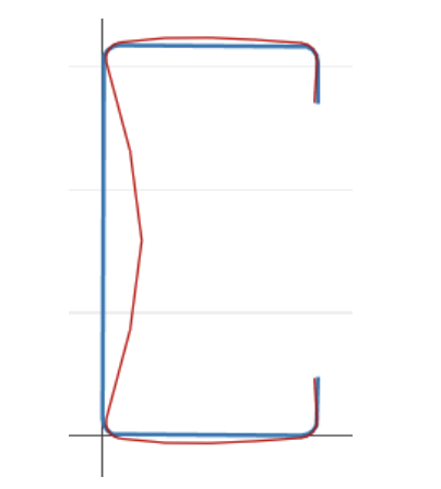
Distortional buckling: Buckling that involves significant distortion of the cross-section, but this distortion includes rotation and translation at one or more internal fold lines of a member [2].
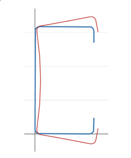
Global buckling: Buckling that does not involve distortion of the cross-section, instead translation (flexure) and/or rotation (torsion) of the entire cross-section occurs [2].
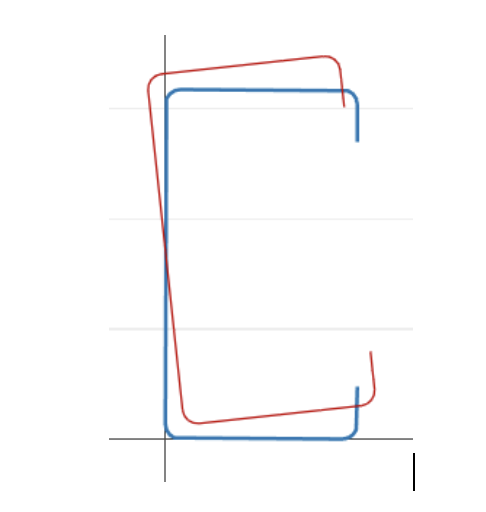
By this definition we can infer that there is a strong geometric correlation between the buckling classification and the deformed shape, we show the deformed for each point of the signature curve.
DSM Factors
Finite Strip Method in SkyCiv Section Builder
SkyCiv has a Direct Strength Method Calculator built into our Section Analysis Software (SkyCiv Section Builder) which can automatically calculate the key DSM factors for any custom cold formed steel shape. Simply start from the Section Builder module by loading in a CFS section and clicking Design -> Cold Formed Steel:
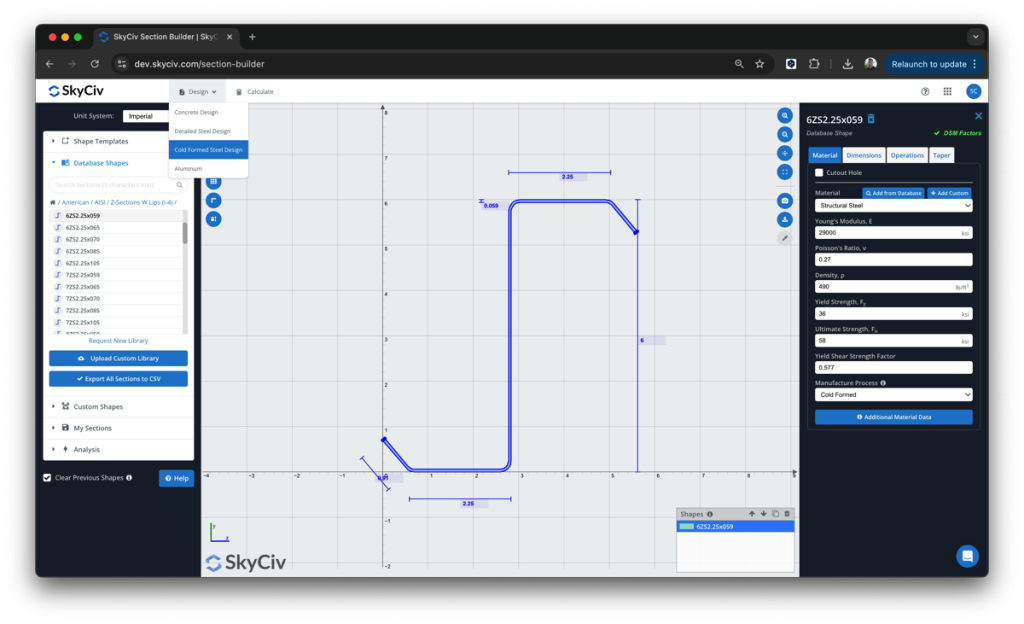
From here, the DSM factors will be automatically calculated, ready for the user to review and submit:
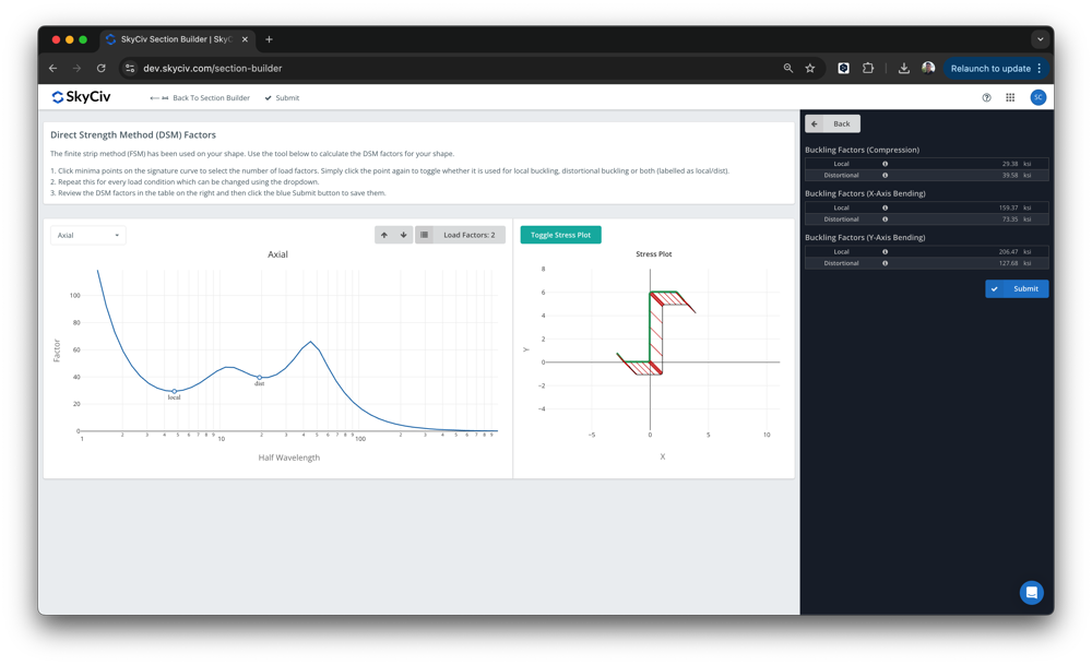
The software is built on top of the SkyCiv Section Builder, under Design – Cold Formed. The local and distortional buckling minima will automatically be detected, however users can override these values. Once submitted, these factors will then be used in the design for the SkyCiv AISI (2016) and AS4600 (2018) integrated design modules.
In SkyCiv elastic buckling analysis module, there are some important hypotheses and considerations that we clarify here. We will explore these below:
Mesh of elements
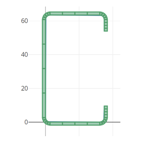
The mesh of the elements is produced automatically and can be viewed in the right chart, the fillets are split into 4 elements, and the straight line into 4 elements too.
Analysis lengths
The lengths used to perform the Finite Strip analysis are defined by default as a logarithmic space from 0 to 10^3 in the imperial unit system and from 0 to 10^3.5 in the metric system.
Load conditions
We calculate the signature curve for 5 different load conditions:
- Axial load
- Bending moment in X axis, positive
- Bending moment in X axis, negative
- Bending moment in Y axis, positive
- Bending moment in Y axis, negative
Boundary Conditions
The analysis is performed assuming the model is pinned and free to warp at both ends.
Signature Curve
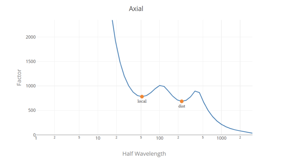
The signature curve is constructed using the conventional Finite Strip Method, Fy is normalized (Fy = 1) so the load factors are presented in pressure units (MPa or ksi according to the unit system).
Load Factor Selection
Generally, the load factors are the local minimum points in the signature curve, the first one representing the critical load factor for local buckling and the second one representing the critical load factor for distortional buckling. Determining the global load factor from the signature curve is a difficult task since there is no local minimum point in the signature curve. So, the most appropriate solution is to use the local and distortional buckling load factors from a Finite Strip analysis and the global buckling factor using the classical formulas.
We use an algorithm to find and classify the load factors in the signature curve. However, this does not ensure a correct classification in all the cases, and this does not replace the engineering judgment, we encourage the user to review the values and modify them if necessary before submitting.
SkyCiv FSM Calculator: Step by Step Guide
To use the FSM module, you must access the section builder and select the section you want to analyze. The section must comply with the following requirements to be analyzed:
- The section must be cold-formed (you can set it in “Manufacture Process”).
- The section must be an open shape from a database or a template of the shapes, Channel, Channel with lips, Zee, Zee with lips, or hat.
- The width must be uniform.
To perform the analysis click on “Design”, “FSM (Cold Formed)”.

If the current section has DSM factors are stored (as many of our database section are), you will be asked to override the previous values:

You will see the signature curve for the default load condition (Axial), the section mesh with the respective stress distribution, and at the right a table with the DSM factor for all the load conditions.

To navigate between the different load conditions, you can use the dropdown at the left or use left and right arrow keys.

Automatically, the software will calculate the appropriate points on the curve. However, this does not ensure a correct classification in all the cases, and this does not replace engineering judgment, so we encourage the user to review the values and modify them if necessary by clicking in the curve to delete or add a point before submitting. Users can also visualize the deformed shape by hovering the cursor over the curve; the deflected (red) shape will be displayed with the original (blue) shape:

After checking all the values, submit the results by clicking on Submit:

The values for that shape will be stored and used in member design cold-formed standards.
Structural Engineer
BEng (Civil), MEng (Structural)
References
- North American Specification for the Design of Cold-Formed Steel Structural Members, 2016 Edition, American Iron and Steel Institute.
- Direct Strength Method (DSM) Design Guide, 2006, Committee on Specifications for the Design of Cold-Formed Steel Structural Members.
- Buckling analysis of cold-formed steel members using CUFSM: conventional and constrained finite strip methods, B.W. Schafer and S. Ádány, 2006, 18th International Specialty Conference on Cold-Formed Steel Structures.
- SkyCiv Cold Formed Steel Member Design Software


