A powerful tool for calculating the stresses of a section
Introduction
SkyCiv Section Builder Analysis is the design tool for calculating cross-sectional stresses resulting from combinations of applied forces and bending moments. The software is capable of the calculating the following stresses:
- Normal stresses from axial force and bending;
- Shear stresses from shear force and torsion;
- Equivalent stresses (von Mises) with comparison to limit stress;
All results can be evaluated numerically and graphically. Furthermore, you can print a PDF report, including all relevant data and a user-defined cross-section graphic. Click here for a sample PDF report.
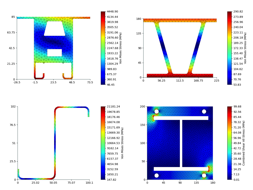
What can be analyzed in the Section Builder?
Below are a few examples of what types of sections can be analysed in the Section Builder:
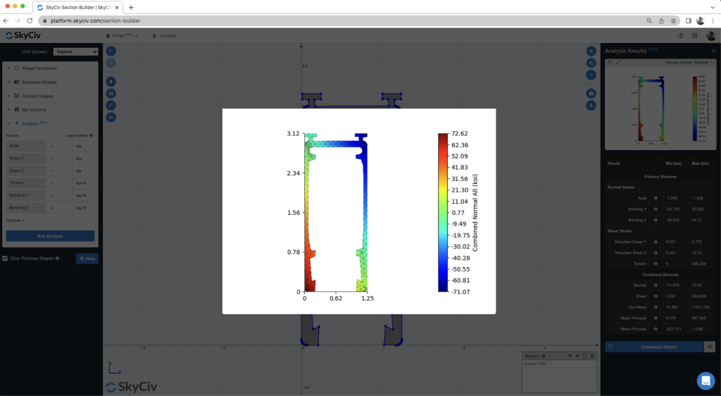
Where can you find the Analysis Module?
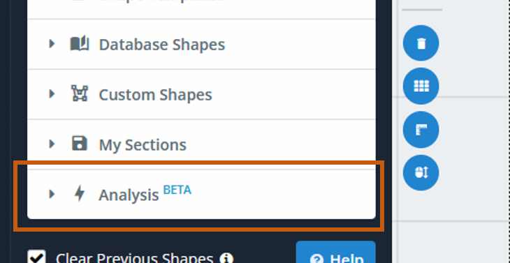
After you have finished defining your section, you can go to the analysis tool by clicking on the “Analysis” section in the left menu panel.
Step 1 – Assign Forces and Options
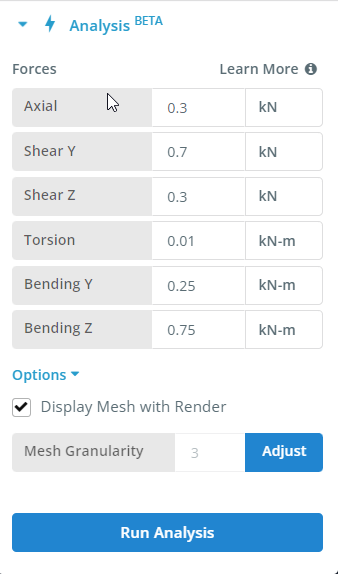
Applying Forces
- Axial – An applied axial force, where compression is positive. The load is applied at the centroid.
- Shear Y – Applied Shear Force in the Y Direction. Positive shear is in the direction of the positive axis. Shear forces applied at the shear center.
- Shear Z – Shear Force in the Z Direction. Positive shear is in the direction of the positive axis. Shear forces applied at the shear center.
- Torsion – Applied torsional moment, counterclockwise is positive, following the right-hand-rule.
- Bending Y – Applied bending moment about Y-Axis. The moment is positive when it compression right fibres of section. The load is applied at the centroid.
- Bending Z – Applied bending moment about Z-Axis. The moment is positive when it compression top fibres of section.
Applying Options
- Display Mesh with Render – Toggle this to choose whether to include the mesh in the results renders.
- Mesh Granularity – The mesh granularity adjustment is used to control how many elements are used in the analysis.
Step 2 – Run Analysis
To start calculation click on the blue “Run Analysis” button at the bottom of the Analysis Tab. This may take from a few seconds to a minute, depending on the complexity of the shape and the mesh granularity set in the settings.
Step 3 – View Results
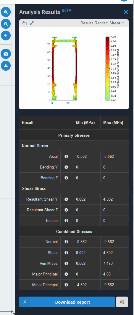
You may select the following for graphical results in the right menu panel “Analysis Result” that appears after finishing of analysis:
Primary Stresses
- Normal Stress
- Axial – stress resulting from the axial load
- Bending Y – stress resulting from the bending moment Myy
- Bending Z – stress resulting from the bending moment Mzz
- Shear Stress
- Resultant Shear Y – resultant shear stress resulting from the shear force Vy
- Resultant Shear Z – resultant shear stress resulting from the shear force Vz
- Torsion – shear stress resulting from the torsion moment
Combined Stresses
- Normal – normal stress resulting from all actions
- Shear – shear stress resulting from all actions
- Von Mises – von Mises stress resulting from all actions
- Major Principal – major principal stress resulting from all actions
- Minor Principal – minor principal stress resulting from all actions
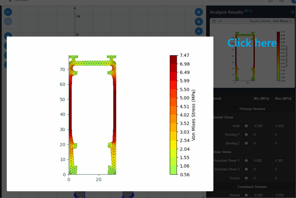
To view the render on a large scale, click on the render and it will open up into a full-screen view.
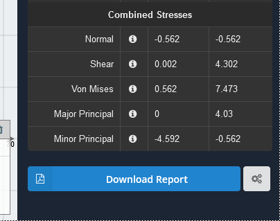
To download a PDF report of the results, you can click on the “Download Report” button at the bottom of the Results Table

