Complex Slab Design Made Easy with SkyCiv Plate Design Module
The SkyCiv Concrete Slab Design module allows users to import plates and shell elements from the structural model to finalize their concrete reinforcement designs. This module includes the ability to:
- Extract Analysis Results
- Define domains or regions for different reinforcement arrangements
- Manually or automatically generate and check required reinforcement
- Supports ACI 318-19, AS 3600 and EN 1992-1-1:2004 Design Standards
Using the RS Slab Design Module
The user interface provides a very clear and smooth workflow for modeling and visualizing results. You will need to define the structural elements and assign properties to them. Then specify the load combinations and assign the reinforcement. In the end, you will be provided with information about the capacity ratio of the structural elements.
Where can you find the RS Slab Design Module?
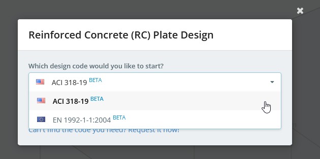
When you are finished with your model in S3D and you have the results, you can go to the design module by clicking:
Design > Start New Code
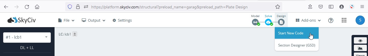
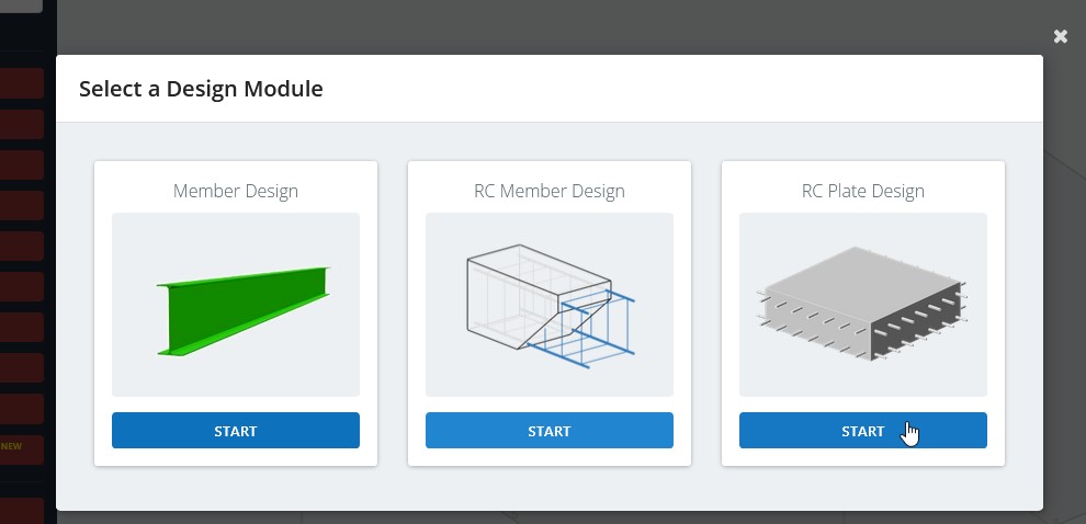
then START the RS Plate Design and the Design Code
Step 1 – Project Information
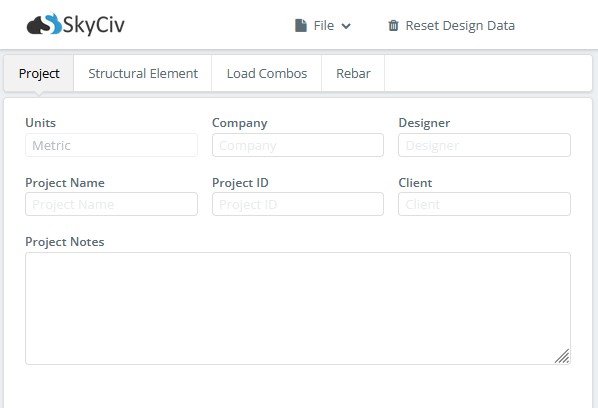
Register the general project information (project name, user name, etc.).
Step 2 – Define Structural Elements
The Structural Element is inputted by selecting some parts of the model and providing specific data through the tabs “Structural Type”, “Arrangement”, “Optimize” and, “Materials/Factors”.
2.1 Structural Type Tab
A Structural Element is a group of FE elements that represent some part of a structure (slab, wall, etc.).
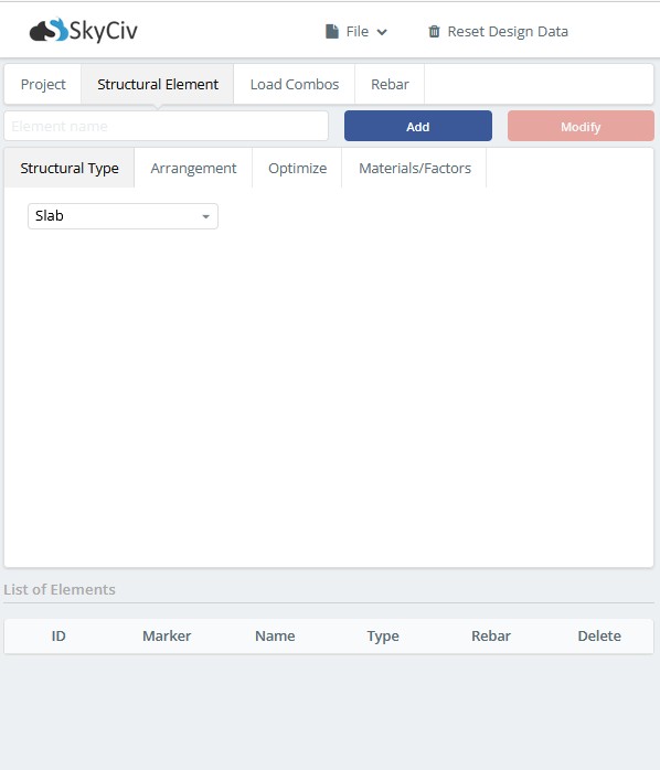
Currently, the module supports only the “Slab” type of structure. This means that only the bending moment internal forces and shear forces will be considered through the design checks.
2.2 Arrangement Tab
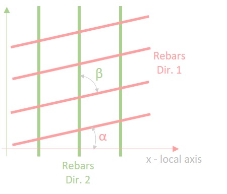
Here the rebar direction and the limit of crack width for the structural member are specified.
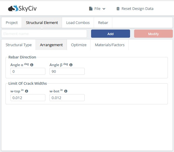
- The Rebar Direction is defined by two parameters – Angle α and Angle β which are specified in degrees.

- The Limit Of Crack Widths is defined for the Top and Bottom surfaces of the element structure. The default values are taken according to the chosen design code.
2.3 Optimize Tab
Here are the parameters to optimize the required area of the main rebar. Currently, the optimizer only supports the strength check to produce the required area of the main rebar. In the future, sustainability criteria will also be included.
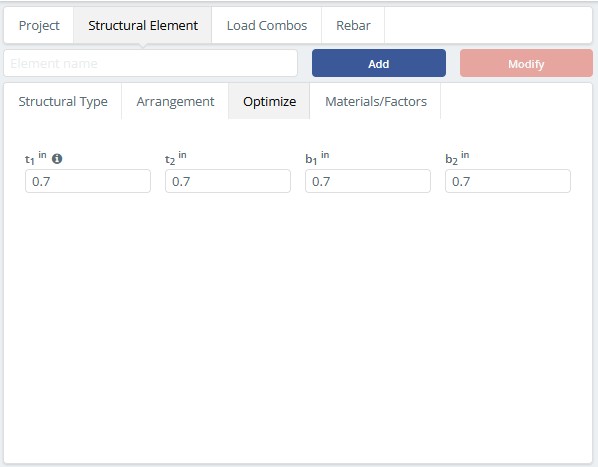
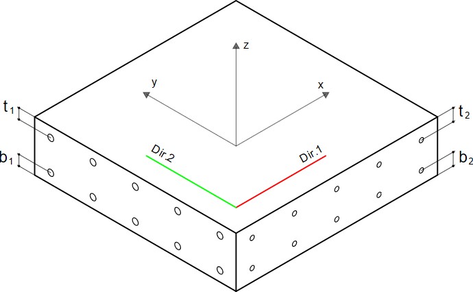
- t1 – is the distance from the top surface of the concrete to the center of the Dir.1 layer of rebars.
- b1 – is the distance from the bottom surface of the concrete to the center of the Dir.1 layer of rebars.
- t2 – is the distance from the top surface of the concrete to the center of the Dir.2 layer of rebars.
- b2 – is the distance from the bottom surface of the concrete to the center of the Dir.2 layer of rebars.
2.4 Materials/Factors Tab
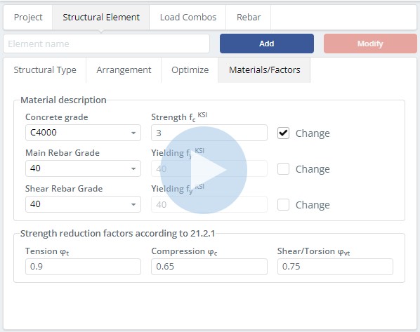
Here are the parameters of concrete material and rebars. The Strength and Yield input boxes show the strength of the selected material. It can be changed by clicking on the Change checkbox.
Step 3 – Load Combos
Here it is specified which load combinations are used for strength checks and which for serviceability checks.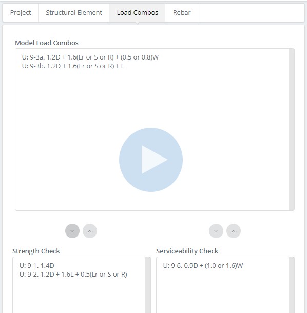
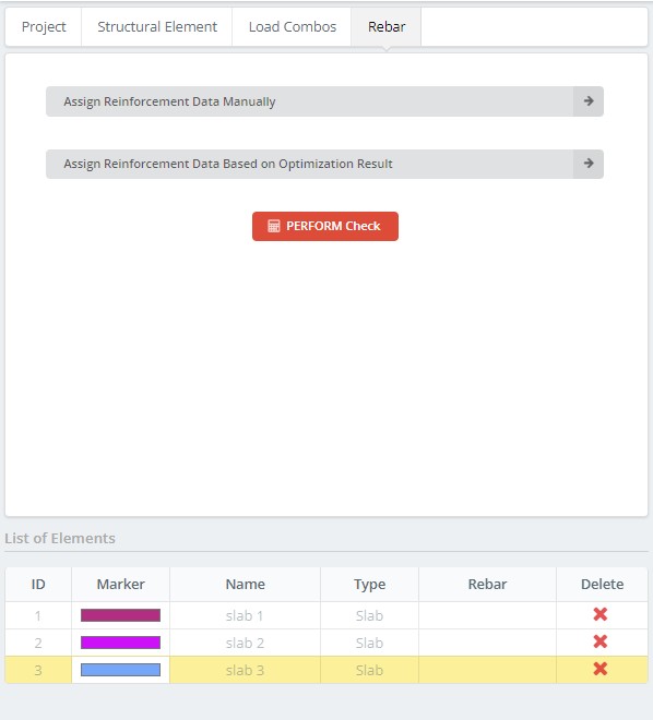
Step 4 – Rebar
Through this tab, you may assign the reinforcement in one of two ways: by selecting the structural element in the List of Elements table and clicking on the button “Assign Reinforcement Data Manually” or “Assign Reinforcement Data Based on Optimization Result”. After assigning reinforcement, it is possible to click PERFORM Check and analysis the capacity ratios.
4.1 Assign Reinforcement Data Manually
To add reinforcement, you may select the structural element in the List of Elements table by clicking on the cell with the “ID” or “Name” column.
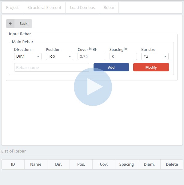
- Direction: the direction of rebar
- Position: assigned the position of rebar
- Cover: the thickness extends from the concrete edge to the outermost rebar surface.
- Spacing: the distance between the rebars
- Bar size: standard rebar sizes used for the slab design
To add the rebar, click on the Add button.
To modify the selected rebar, click on the Modify button after changing the required parameters.
4.2 Assign Reinforcement Data Based on Optimization Result
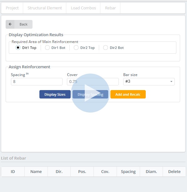
- Dir1 Top: display contour of the required area of main reinforcement for the top layer in Dir 1
- Dir1 Bot: display contour of the required area of main reinforcement for the bottom layer in Dir 1
- Dir2 Top: display contour of the required area of main reinforcement for the top layer in Dir 2
- Dir2 Bot: display contour of the required area of main reinforcement for the bottom layer in Dir 2
To display the size or spacing of the rebar for the selected area, click on the “Display Sizes” or “Display Spacing” buttons.
To assign the reinforcement, click on the “Add and Recalc” button. The module will calculate the new required area of reinforcement considering the assigned rebar.
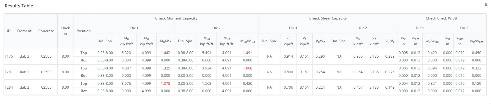
4.3 PERFORM Check
Once reinforcements are assigned, a capacity check can be performed by clicking on the “PERFORM Check” button.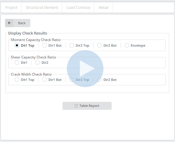
Moment Capacity Check Ratio
- Dir1 Top: display contour of the moment capacity ratio for the top layer in Dir 1
- Dir1 Bot: display contour of the moment capacity ratio for the bottom layer in Dir 1
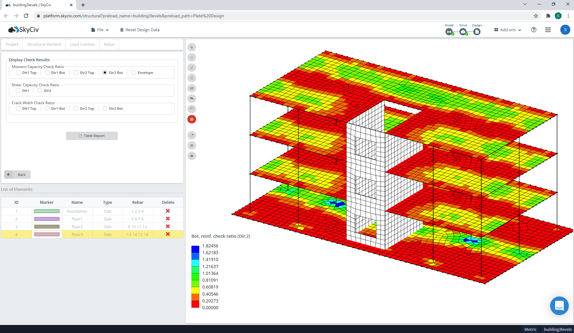
- Dir2 Top: display contour of the moment capacity ratio for the top layer in Dir 2
- Dir2 Bot: display contour of the moment capacity ratio for the bottom layer in Dir 2
- Envelope: display contour of the maximum value of the moment capacity ratio from each layer and Dir
Shear Capacity Check Ratio
- Dir1: display contour of the shear capacity ratio for the Dir 1
- Dir2: display contour of the shear capacity ratio for the Dir 2
Crack With Check Ratio
- Dir1 Top: display contour of the crack width check ratio for the top layer in Dir 1
- Dir1 Bot: display contour of the crack width check ratio for the bottom layer in Dir 1
- Dir2 Top: display contour of the crack width check ratio for the top layer in Dir 2
- Dir2 Bot: display contour of the crack width check ratio for the bottom layer in Dir 2
To display the detailed result for each FE element, select FE elements and click the “Table Report” button.