Foundation is an essential element of a structure to provide overall stability by transmitting and distributing the total loads of the structure to the ground. Shallow foundations, such as rectangular or square isolated footing, are the preferred type of foundation due to the simplicity of their construction and overall cost compared to deep foundations. Estimating the base pressure dramatically affects the design and sizing of the footing. Typically, the utility ratio between the allowable bearing capacity of the soil and the governing base pressure under the footing is the basis of the initial size of the footing. Once the initial footing dimensions are set, further design checks for safety and stability, such as one-way and two-way shear, bending capacity, and development length checks, are checked depending on which design code is used.
When a footing is subjected to a bi-axial bending (Mx, Mz), it is assumed that the axial load (P) is acting on an eccentricity coordinate (ex, ez) where there is a tendency to rotate from the center. The interaction between the soil and footing mainly depends on the footing dimension and the resultant eccentricity of the applied loads. Depending on the location of the resultant eccentricity, the base pressure causes the footing to be in full or partial compression. In practice, it is recommended to design a footing in full compression. Partial compression or loss of contact between the soil and footing should not be neglected, but most designers avoid this scenario due to its calculation complexity. Footing is in full compression when the resultant eccentricity is located within the kern or under Zone C. Eccentricity outside Zone C puts the footing in partial compression. Figure 1 shows the different designated zones on a rectangular footing.
This article shall focus on calculating corner pressures under different zone classifications based on Bellos & Bakas (2017) and S.S. Ray’s (1995) studies.
Zone classifications of a rectangular footing
The zone classifications of a rectangular footing are derived from multiple studies by different authors to develop a practical approach to estimating the distribution of soil pressure under expected loading conditions. As shown in Figure 1, there are five different regions (Zones A-E) depending on the location of resultant eccentricity. Each zone corresponds to a different loading, base pressure distribution, and deformation. Zone C, also known as the kern, is the main core. It is the ideal region to design a footing, resulting in full compression on the footing. The dimensions of this region are equivalent to 1/6 of its respective footing length.
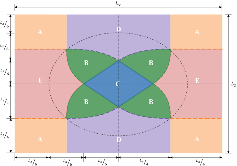
Figure 1: Zone classifications of a rectangular footing
The secondary core is the elliptical area (bounded by the dashed line in Figure 1) with its major and minor semi-axes equal to 1/3 of its respective footing length. This region covers the entire zones B & C and some parts of zones D & E. Secondary core results in a partial compression of the footing. It is a good practice to maintain the eccentricity inside the secondary zone for an acceptable footing design.
Eccentricity beyond the secondary zone is the result of high bi-axial loading. It covers the entire zone A and the remaining parts of zones D & E. It is recommended to avoid designing the footing in these regions as it will have the risk of overturning. Hence, it is advisable to redesign the footing dimensions for this loading type.
The following enumerates the analytical formulas for solving the corner pressures in each zone classification.
Zone C (Main core, Full compression zone)
As mentioned, this is the most preferred case for designing footings since it is capable of setting the whole base of the footing into compression, as shown in Figure 2. This case is represented by small eccentricity within the kern or no eccentricity. Figure 2 shows the eccentricity within the kern with its maximum pressure at corners P3 & P4 and minimum pressure at corners P1 & P2.
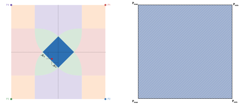
Figure 2: Eccentricity (-ex, -ez) at Zone C & full compression area
Maximum & minimum corner pressures (Bellos & Bakas, 2017):


| Corner pressures based on eccentricity | ||||
|---|---|---|---|---|
| P1 | P2 | P3 | P4 | |
| +ex, +ez | Pmax | Pmax | Pmin | Pmin |
| +ex, -ez | Pmax | Pmax | Pmin | Pmin |
| -ex, -ez | Pmin | Pmin | Pmax | Pmax |
| -ex, +ez | Pmin | Pmin | Pmax | Pmax |
Zone A (Triangular compression zone)
This case corresponds to four rectangular areas in every corner of the footing. It usually occurs with large bi-axial eccentricity, imposing a high triangular compressive area in one of the corners, as shown by the shaded region in Figure 3. The remaining corners lose contact with the soil. Hence, this case is not advisable for design.
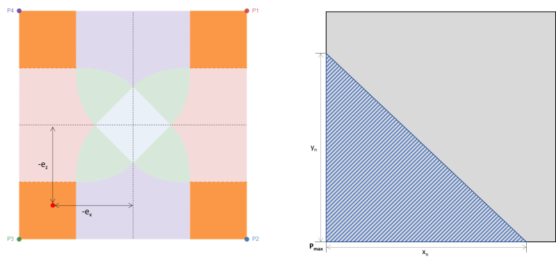 Figure 3: Eccentricity (-ex, -ez) at Zone A & triangular compression area around P3
Maximum pressure (Bellos & Bakas, 2017):

| Corner pressures based on eccentricity | ||||
|---|---|---|---|---|
| P1 | P2 | P3 | P4 | |
| ex(+), ez(+) | Pmax | 0 | 0 | 0 |
| ex(+), ez(-) | 0 | Pmax | 0 | 0 |
| ex(-), ez(-) | 0 | 0 | Pmax | 0 |
| ex(-), ez(+) | 0 | 0 | 0 | Pmax |
Zone D (Trapezoidal compression zone)
Zone D also corresponds to large eccentricities in the areas attached in the x-direction of the footing, as shown in Figure 4. The eccentricity in the z-direction (ez) is much greater than in the x-direction (ex). In this case, two corners of the footing lose contact with soil and produce a trapezoidal compressive area. Compared to zone A, which is entirely outside the secondary zone, a portion of zone D is still covered by the secondary zone.
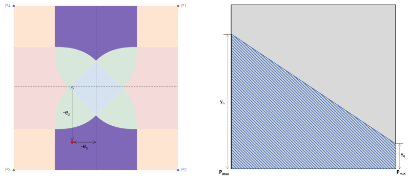
Figure 4: Eccentricity (-ex, -ez) at Zone D & trapezoidal compression area around P3
Maximum & minimum corner pressures (Bellos & Bakas, 2017):


Vertical heights of the trapezoidal compressive area (Bellos & Bakas, 2017):


| Corner pressures based on eccentricity | ||||
|---|---|---|---|---|
| P1 | P2 | P3 | P4 | |
| ex(+), ez(+) | Pmax | 0 | 0 | Pmin |
| ex(+), ez(-) | 0 | Pmax | Pmin | 0 |
| ex(-), ez(-) | 0 | Pmin | Pmax | 0 |
| ex(-), ez(+) | Pmin | 0 | 0 | Pmax |
Zone E (Trapezoidal compression zone)
Similar to zone D, this case also produces a trapezoidal compressive area but is caused by a large eccentricity in the x-direction(ex).
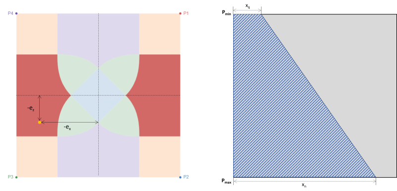 Figure 5: Eccentricity (-ex, -ez) at Zone E & trapezoidal compression area around P3
Maximum & minimum corner pressures (Bellos & Bakas, 2017):


Horizontal bases of the trapezoidal compressive area (Bellos & Bakas, 2017):


| Corner pressures based on eccentricity | ||||
|---|---|---|---|---|
| P1 | P2 | P3 | P4 | |
| ex(+), ez(+) | Pmax | Pmin | 0 | 0 |
| ex(+), ez(-) | Pmin | Pmax | 0 | 0 |
| ex(-), ez(-) | 0 | 0 | Pmax | Pmin |
| ex(-), ez(+) | 0 | 0 | Pmin | Pmax |
Zone B (Pentagonal compression zone)
This case occurs when the applied loads on the footings generate a moderate eccentricity within the secondary zone. The areas covered by zone B are bounded by two curved sides and one flat base around the exteriors of zone C. In this case, a pentagonal compressive area is produced, and only a corner of the footing loses contact with the soil. However, the solutions provided below are slightly complex and require numerical solving methods for the corner pressures and the x & y intercepts of the compressive area.
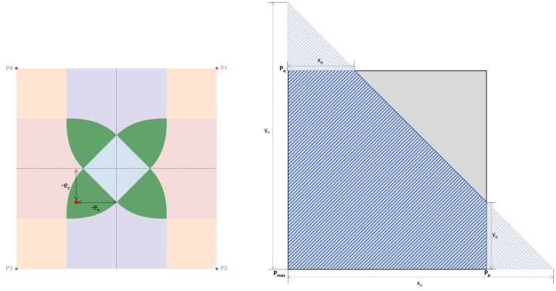
Corner pressures (Bellos & Bakas, 2017):


Pentagonal sides of the compressive area (Bellos & Bakas, 2017):


| Corner pressures based on eccentricity | ||||
|---|---|---|---|---|
| P1 | P2 | P3 | P4 | |
| ex(+), ez(+) | Pmax | Pq | 0 | Pp |
| ex(+), ez(-) | Pp | Pmax | Pq | 0 |
| ex(-), ez(-) | 0 | Pp | Pmax | Pq |
| ex(-), ez(+) | Pq | 0 | Pp | Pmax |
Alternatively, a more direct solution by S.S. Ray (1995) can be used for the corner pressures and intercepts of the pentagonal compressive zone. The equations are given below:
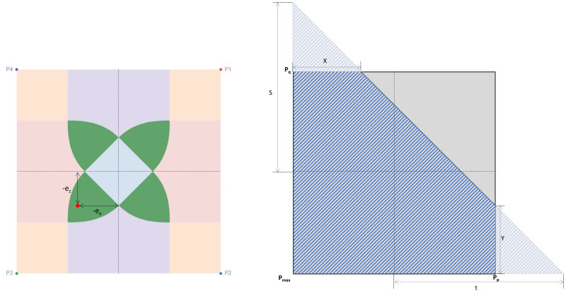
Corner pressures (S.S. Ray, 1995):


Pentagonal sides of the compressive area (S.S. Ray, 1995):


SkyCiv’s Foundation Design Module is capable of solving the base pressures of a rectangular concrete footing. Additional design checks in accordance with different design codes (ACI 318-14, Australian standard 2009 & 2018, Eurocode, and Canadian standards) are also available.
Latest Update
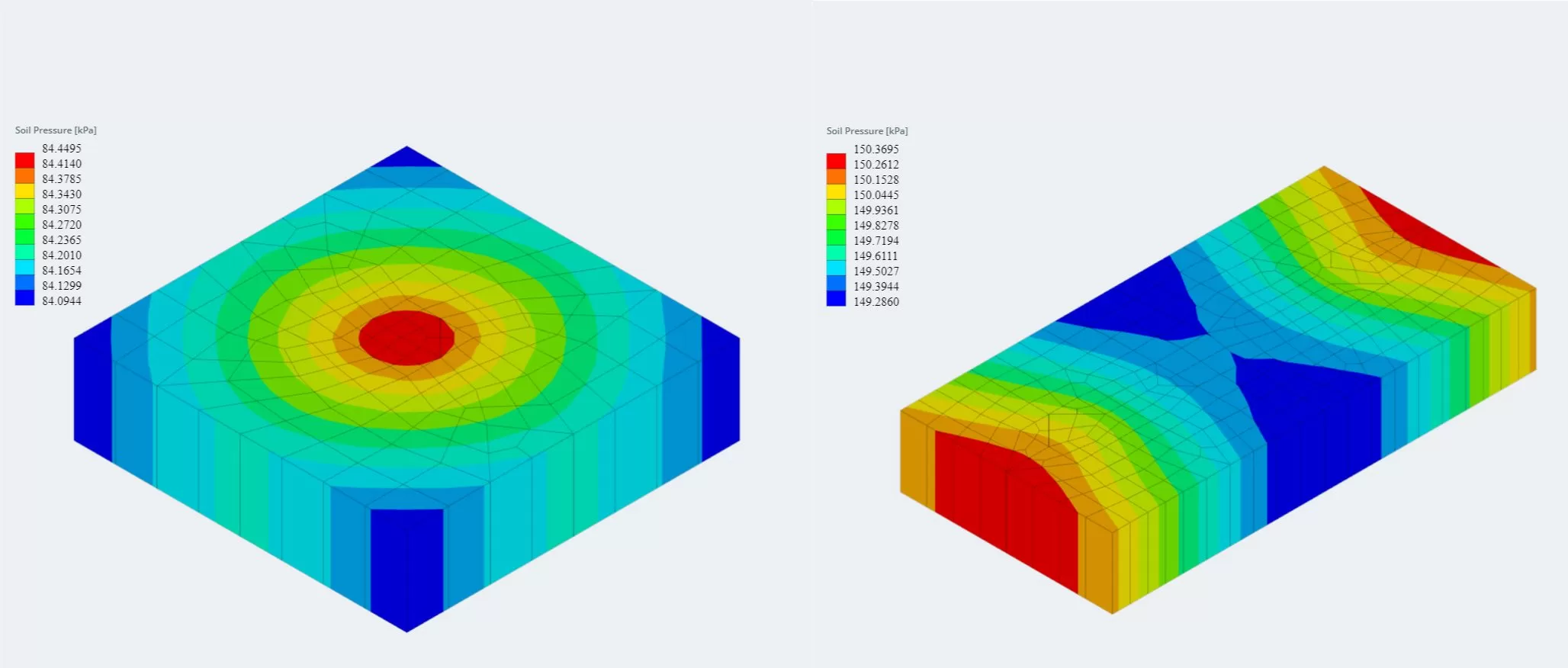
The latest version of the foundation module is now integrated with Finite Element Analysis (FEA), which offers a more powerful soil pressure analysis and introduces wood armer analysis to be used for a much more detailed flexural check. FEA results for the soil pressure and wood armer moments can be viewed in 3D and were added to the reports.
Want to try SkyCiv’s Foundation Design software? Our free tool allows users to perform concrete footing calculations without any download or installation!
References:
- Bellos, J., Bakas, N. (2017). Complete Analytical Solution for Linear Soil Pressure Distribution under Rigid Rectangular Spread Footing.
- Das, B.M. (2007). Principles of Foundation Engineering (7th Edition). Global Engineering
- Rawat, S., et. al. (2020). Isolated Rectangular Footings under Biaxial Bending: A Critical Appraisal and Simplified Analysis Methodology.
- Ray, S.S. (1995). Reinforced Concrete. Blackwell Science
Product Developer
BSc (Civil), MSc (Civil)


