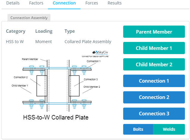
The connection, in the connection assembly, refers specifically to the dimensions, material properties, and fixture configuration of the connector.
It should be noted that a connection assembly may have more than 1 connection. For example, this is the case for a Collared Plate assembly, whereby the assembly is comprised of 3 connections; the collared plate, the left shear connection (e.g. a Single Plate connection), and the right shear connection (e.g. another Single Plate connection). The assembly image will identify which connection is which. Click the connection buttons to edit the individual connection.
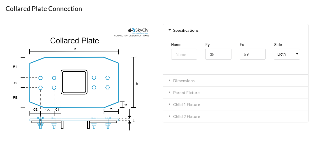
Specifications
Edit the connection’s material properties and side here. The name field is optional.
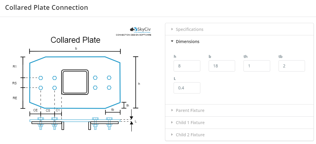
Dimensions
The dimensions of your connection, as specified by the drawing on the left.
Parent Fixture
The parent fixture fields relate to the parent member (in this example the HSS column), and how the connection (the Collared Plate) fixes to it. The fields that are available are the member ID of the parent member, the connecting side of the parent member (e.g. for HSS the breadth wall or the height wall), the fixture type (welds or bolts), the fixture ID (you define bolts / welds in their own popup and reference them by their ID), and the fixture specifications. In this example, the weld laps are editable for the parent fixture.
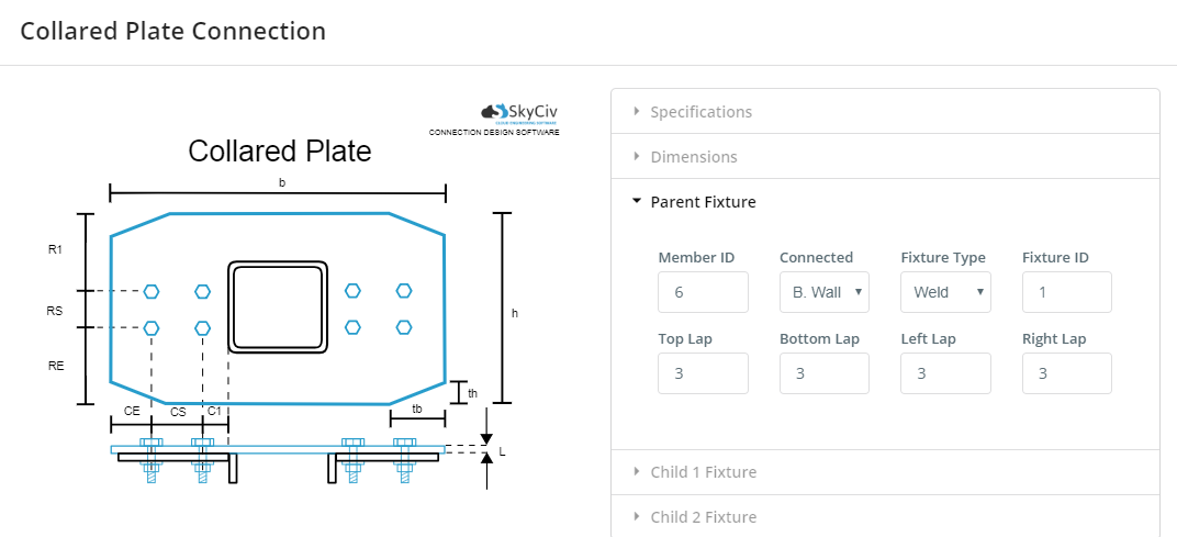
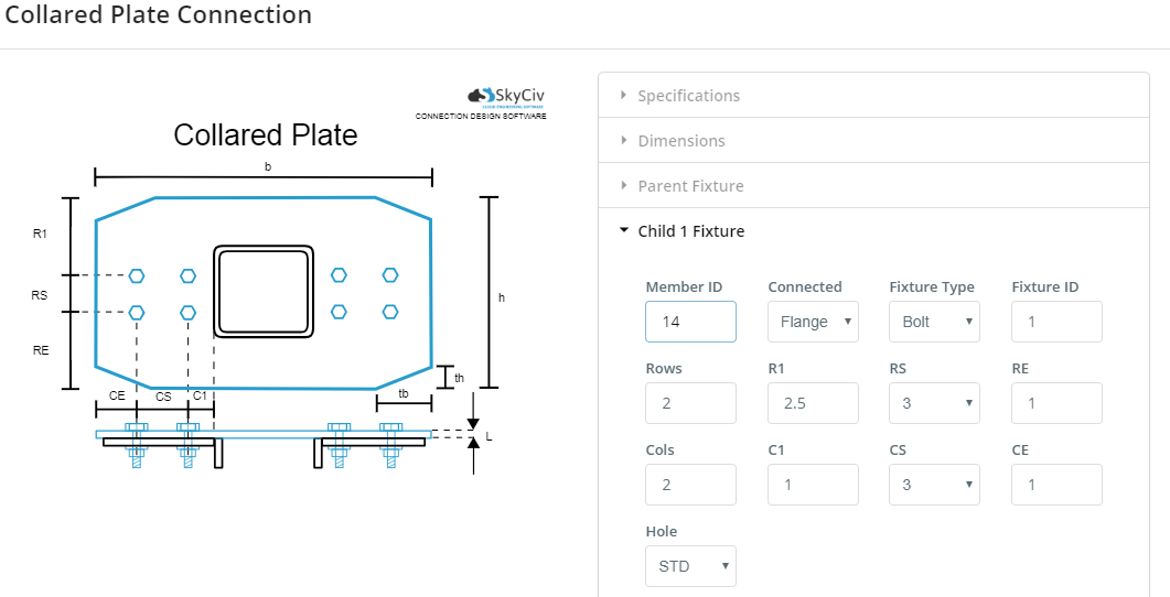
Child (Number) Fixture
The child fixture fields relate to the particular child member (in this example the W beam), and how the connection (the Collared Plate) fixes to it. Note that each child (number) fixture, relates to the specific child (number) member. The fields that are available are the member ID of the child member, the connecting side of the parent member (e.g. for W, the flange or web), the fixture type (welds or bolts), the fixture ID (you define bolts / welds in their own popup and reference them by their ID), and the fixture specifications. In this example, the bolt pattern (by rows, columns, R1, RS, RE, C1, CS, CE) and hole specification are editable.
