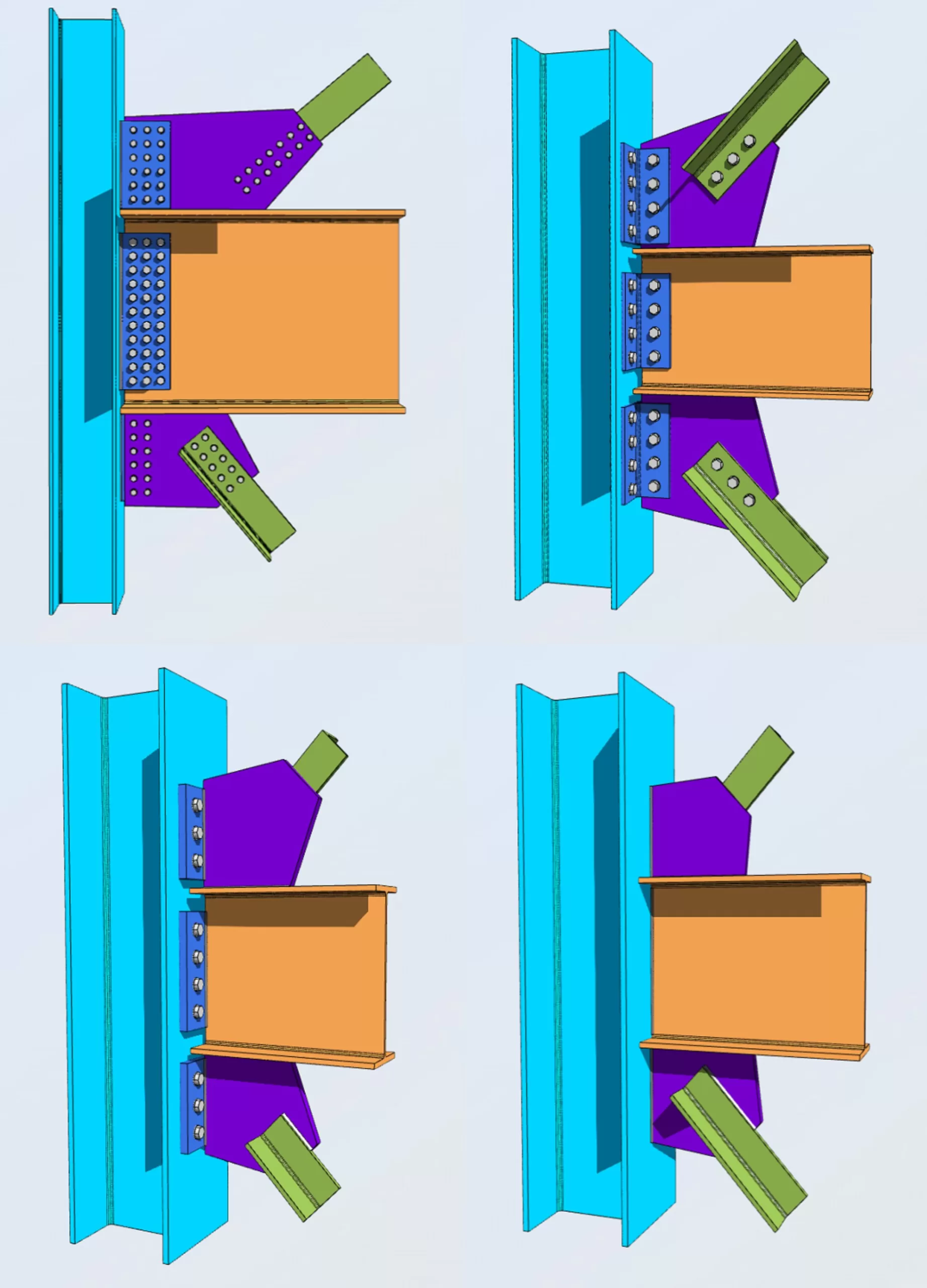
Vertical brace connections are the unsung heroes of structural stability, tasked with fortifying steel structures against lateral forces. In structural engineering, AISC 360-16 standard serves as a reference, offering methodologies for both Allowable Stress Design (ASD) and Load and Resistance Factor Design (LRFD).
SkyCiv’s integration of AISC 360-16 ASD/LRFD vertical brace connections streamlines the design process, offering intuitive tools and advanced analysis capabilities. From an easy-to-use interface to cloud-based collaboration, SkyCiv empowers engineers to navigate complex structural challenges with ease.
Advantages of Bracing Systems Over Moment Frame Systems
In the realm of structural engineering, bracing systems hold several advantages over moment frame systems:
- Cost-Effectiveness: Bracing systems typically require less material and labor compared to moment frame systems, resulting in cost savings during construction.
- Efficient Lateral Load Resistance: Bracing systems excel in resisting lateral loads, efficiently transferring these forces to the building’s foundation. This provides robust stability, especially in areas prone to high winds or seismic activity.
- Flexibility in Layout: Bracing systems offer flexibility in building layout and architectural design. The strategic placement of braces within the structure minimally impacts usable space and aesthetics.
Now onto using the SkyCiv Vertical Brace Connection Calculator…
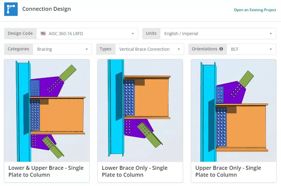
The Design Code can be AISC 360-16 ASD or LRFD. Units can be English/Imperial or SI/Metric. Now click any of the tile. You can choose from 4 different connection types to column: Single Plate, Double Angle, End Plate, and Directly Welded. You can also choose if the brace is lower only, upper only or both.
Project Tab
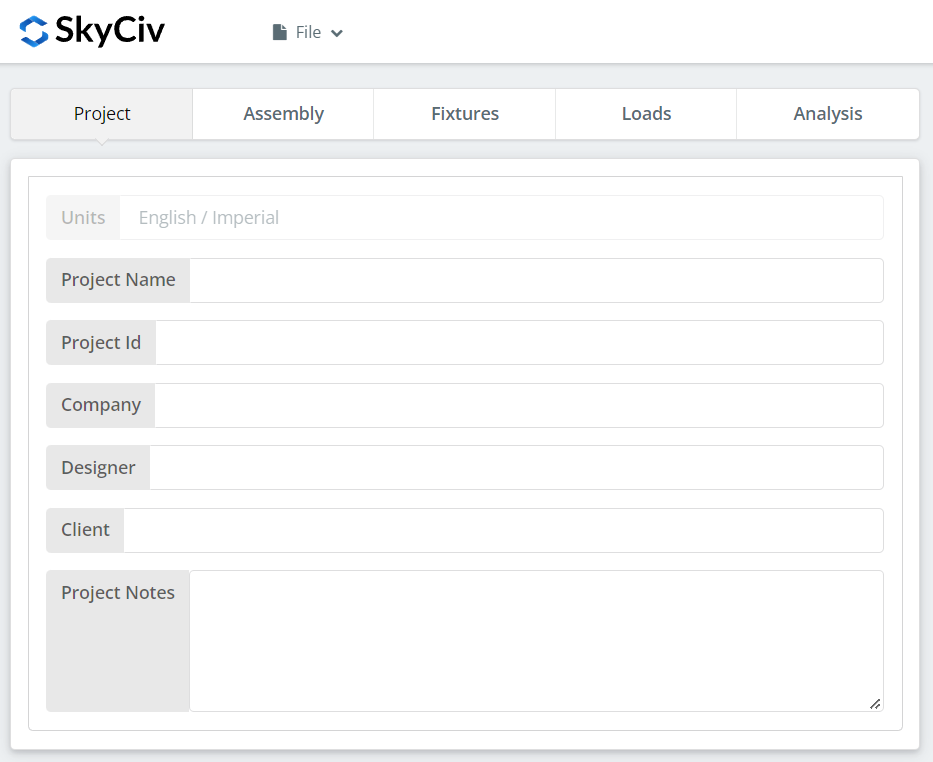
Here you can specify the details of the project you are currently working.
Assembly Tab
There are four or five tabs under Assembly. This is where you specify the Column, Beam, Braces, and Connection Plate or Angle properties.
Column Tab

Beam Tab

Lower or Upper Brace Tab
You can select many different brace shapes. Single Angles, Double Angles, Square and Rectangular HSS, and WT Sections.
Connection Tab
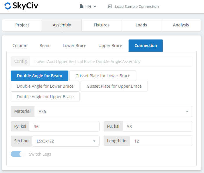
This is where you fill in the connection plate and/or angle properties. For this example, we selected the “Lower and Upper Brace – Double Angle to Column” tile.
Fixtures Tab
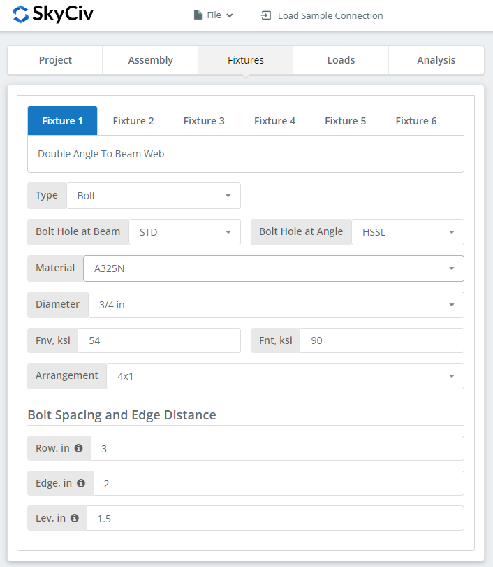
This is where you set your bolts and welds information. Beam to Column Connection, Brace to Gusset Connection, Gusset plate to Beam and Column Connections.
Loads Tab
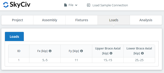
This is where you specify the loads. Make sure to hover over the tooltips for additional information.
Analysis Tab
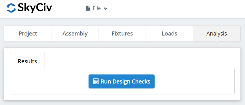
And finally, click “Run Design Checks”. If you missed any needed inputs on the previous tabs, this will notify you to fill in the missing inputs.
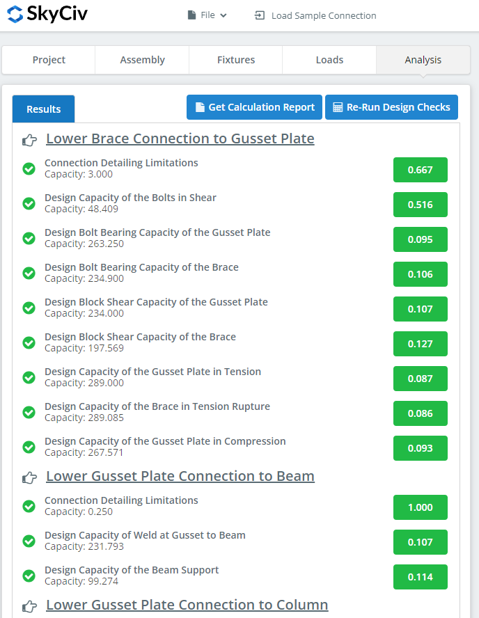
After clicking “Run Design Checks”, you can see a summary if your connection failed or not. If it failed, manually change the inputs in the previous tabs and then, click “Re-Run Design Checks”. When it’s finally okay, click “Get Calculation Report” to see the detailed report.

What you see above is a snippet of the detailed calculation report. As you can see, there is a reference to the AISC manual and/or specification. This should make it easier for the signing engineer to cross-check the calculations. Our calculations are very readable. It is written similar to how it’s written in the manual, specification, or design guides.
Here‘s a PDF copy of the full detailed calculation report. Check it out!


