Launch the software by clicking Base Plate Design from the platform. Start by selecting a design code and choosing a starting template. Click here for the list of supported design codes.
Details Tab
Define project information and configure project settings.
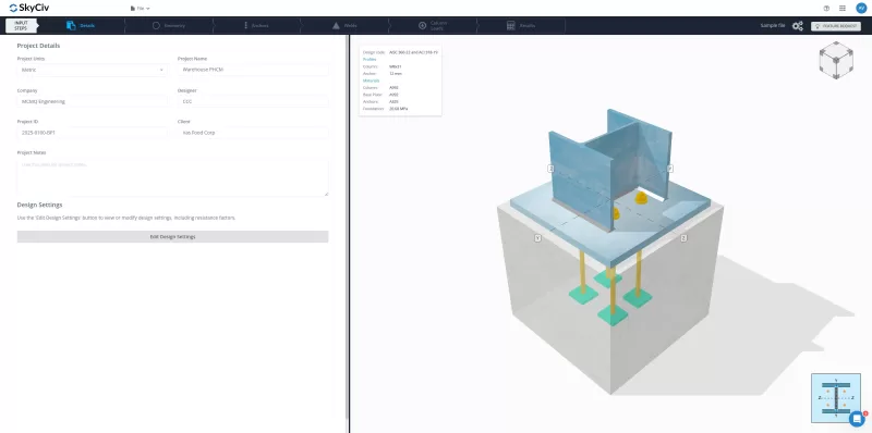
- Set project units (if applicable).
- Enter project details: Project Name, Company, Designer, Project ID, Client, and Notes. These details appear in the report.
- Configure design factors and check options under Design Settings. Default values are available.
Geometry Tab
Define column section, base plate dimensions, and concrete properties.
Column Tab
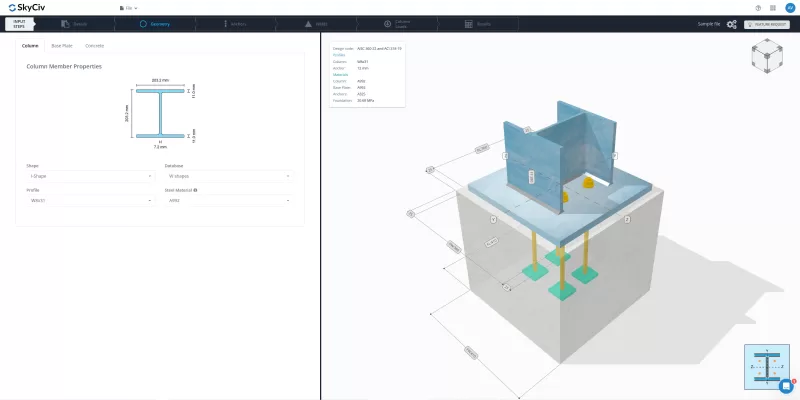
- Modify column shape and section type from the provided options.
- Select a material from the dropdown or enter custom values (Fy, Fu).
Base Plate Tab
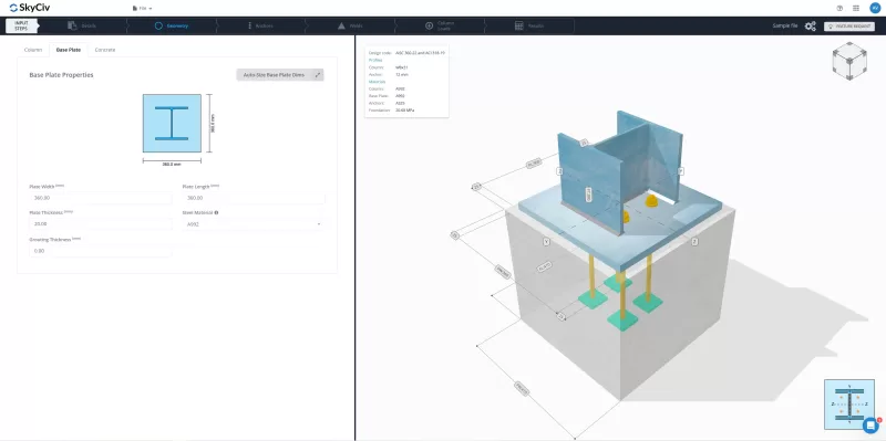
- Adjust base plate width, length, and thickness.
- Add grout and specify thickness.
- Select a material from the dropdown or enter custom values (Fy, Fu).
- Use Auto-Size to adjust base plate dimensions relative to column dimensions. Note: This feature does NOT change size based on strength.
Concrete Tab
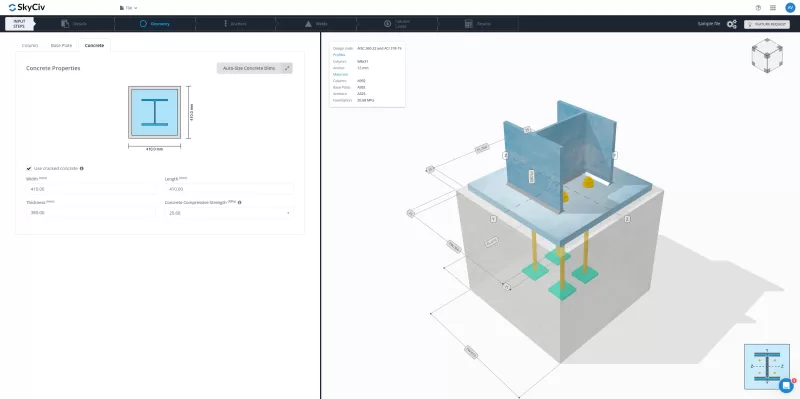
- Specify cracked or uncracked concrete.
- Set concrete dimensions (width, length, thickness).
- Select concrete compressive strength from the dropdown or enter custom a value.
- Use Auto-Size to adjust concrete dimensions relative to base plate dimensions. Note: This feature does NOT change size based on strength.
Anchors Tab
Select anchor properties, position, and failure checks.
Properties Tab

- Choose anchor diameter and material.
- Define the embedded end shape: straight, plate, or hook. For plate or hook, input plate dimensions or hook dimensions
- Input embedment length (hef). See illustrative guide for the extents considered.
Position Tab
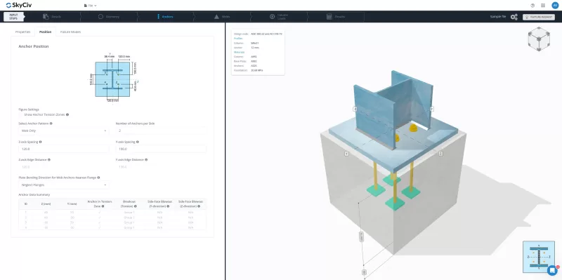
- Select an anchor pattern.
- Adjust number of anchors, its spacing and or edge distances, if applicable
- Use the 3D render or illustrative guide to visualize placement.
- Enable Show Anchor Tension Zones in the figure settings for visual guidance. Only anchors in the tension zone will be activated for the tension load.
- Check Anchor Data Summary for all information about the anchor – anchor ID, coordinates, tension zone indication, and group behavior in checks.
Failure Modes Tab
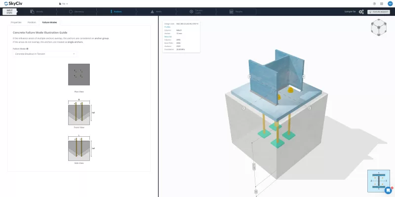
- Select the failure mode from the dropdown menu to view graphical representations of concrete failure modes
- No setup needed here—just a helpful guide to review possible anchor failures.
Welds Tab
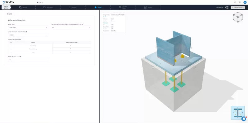
- Choose weld type: fillet or CJP/FPBW.
- Set weld material and size.
- Adjust weld setback for I-shaped sections if needed. See 3D render for visualization.
- Select compression load transfer method: welds or direct bearing. The default is direct bearing.
Column Loads Tab
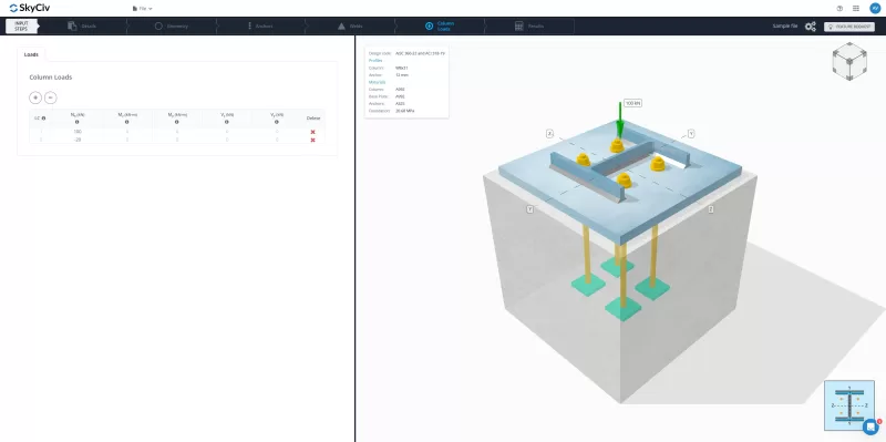
- Supports axial load only (additional load types coming soon).
- Enter factored load in the Nx column (positive = compression, negative = tension).
- Use the buttons to add/remove load combinations.
- Click on the load input cell to see visualization in the 3D render.
Results Tab
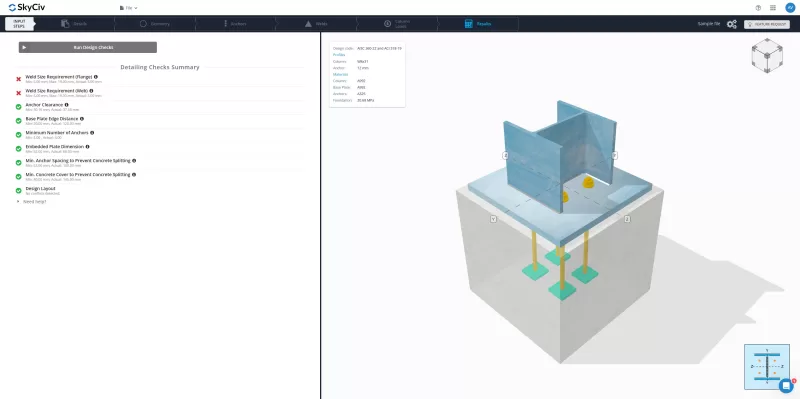
- The Detailing Check Summary provides a comprehensive review of geometry compliance and conflict detection.
- Adjust the indicated dimension if a check fails.
- Modify the list of detailing checks in Design Settings, if necessary.
Running Your Base Plate Design Checks
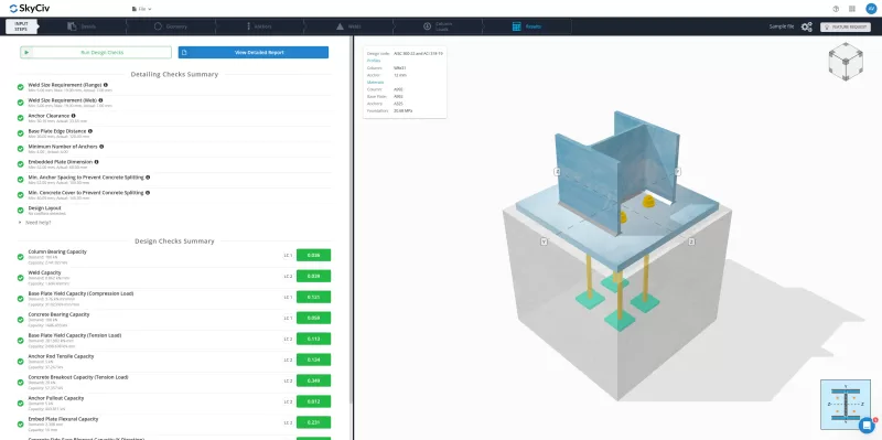
- Click Run Design Checks to analyze the design once set up is complete.
- If certain detailing checks fail but are considered acceptable, click Run Design Checks, then select Run Anyway (if available).
Note: If the Run Anyway button is unavailable, geometry adjustments are required.
- If certain detailing checks fail but are considered acceptable, click Run Design Checks, then select Run Anyway (if available).
- The Design Checks Summary will appear below the Detailing Checks Summary, displaying:
- Performed checks
- Demand and Capacity values
- Ratios
- Governing load combination (LC)
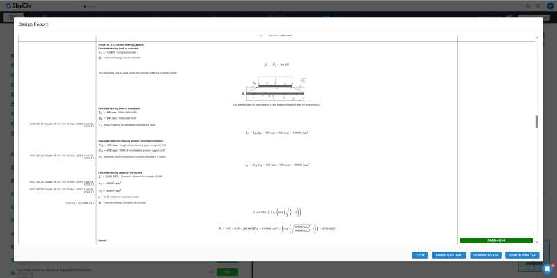
- Click View Detailed Report to preview and download the calculation report.
Try the Free Tool
Setting up your first base plate model takes less than 10 minutes. Try the free SkyCiv Base Plate Design Calculator today!