Base Plate Design Example using CSA S16:19 and CSA A23.3:19
Problem Statement
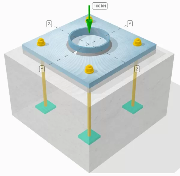
Determine whether the designed column-to-base plate connection is sufficient for a 100-kN compression load.
Given Data
Column:
Column section: HS152X6.4
Column area: 2910 mm2
Column material: 230G
Base Plate:
Base plate dimensions: 350 mm x 350 mm
Base plate thickness: 20 mm
Base plate material: 230G
Grout:
Grout thickness: 20 mm
Concrete:
Concrete dimensions: 450 mm x 450 mm
Concrete thickness: 300 mm
Concrete material: 20.68 MPa
Welds:
Compression load transferred through welds only? NO
Model in SkyCiv Free Tool
Model the base plate design above using our free online tool today! No sign-up required.
Step-by-Step Calculations
Check #1: Calculate bearing capacity of column
Since the compression load is not transferred through welds alone, a proper contact bearing surface is required to ensure that the load is transferred via bearing. Refer to CSA S16:19 Clause 28.5 for contact bearing preparation.
To calculate bearing capacity of the column, we will use CSA S16:19 Clause 13.10:
\( B_r = 1.50 \phi F_{y\_col} A_{col} = 1.5 \times 0.9 \times 230 \, \text{MPa} \times 2910 \, \text{mm}^2 = 903.55 \, \text{kN} \)
Since 100 kN < 903.55 kN, the column bearing capacity is sufficient.
Check #2: Calculate weld capacity
Use minimum weld size specified in CSA S16:19.
Check #3: Calculate base plate flexural yielding capacity due to compression load
The flexural capacity of the base plate depends on its dimensions. If the plate is too wide, it will require thicker material. Selecting the right base plate size for a given load requires experience, and performing multiple calculations can be time-consuming. The SkyCiv Base Plate Design software simplifies this process, enabling fast and efficient modeling and analysis in just seconds.
First, we determine the critical cantilever length, which is the larger of dimension m and dimension n. We follow AISC Design Guide 01 3rd Ed. Section 4.3.1 as a reference.
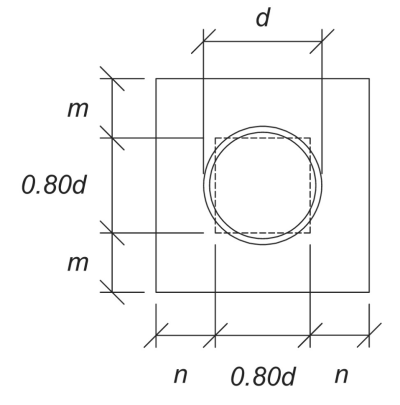
\( l = \max \left( \frac{L_{bp} – 0.8 d_{col}}{2}, \frac{B_{bp} – 0.8 d_{col}}{2} \right) \)
\( l = \max \left( \frac{350 \, \text{mm} – 0.8 \times 152 \, \text{mm}}{2}, \frac{350 \, \text{mm} – 0.8 \times 152 \, \text{mm}}{2} \right) = 114.2 \, \text{mm} \)
Once the critical length is identified, we calculate the applied moment per unit length, assuming the full compression load is uniformly distributed over the base plate area:
\( m_f = \left( \frac{N_x}{B_{bp} L_{bp}} \right) \left( \frac{l^2}{2} \right) \)
\( m_f = \left( \frac{100 \, \text{kN}}{350 \, \text{mm} \times 350 \, \text{mm}} \right) \times \left( \frac{114.2 \, \text{mm}^2}{2} \right) = 5.3231 \, \text{kN} \cdot \text{mm/mm} \)
Now, using CSA S16:19 Clause 13.5, we compute the flexural capacity per unit length:
\(
m_r = \phi \left( \frac{(t_{bp})^2}{4} \right) F_{y_bp} = 0.9 \times \left( \frac{(20 \, \text{mm})^2}{4} \right) \times 230 \, \text{MPa} = 20.7 \, \text{kN} \cdot \text{mm/mm}
\)
Since 5.3231 kN-mm/mm < 20.7 kN-mm/mm, the base plate flexural capacity is sufficient.
Check #4: Concrete bearing capacity
The final check ensures that the concrete can support the applied load. While a wider concrete base increases bearing capacity, an efficient design must balance strength and cost-effectiveness. Now, let’s determine if our concrete support has sufficient capacity.
To start, we determine the bearing areas:
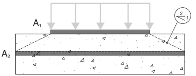
A1 – Base plate bearing area
A2 – Concrete support bearing area, projected at a 2:1 slope
\(
A_1 = L_{bp} B_{bp} = 350 \, \text{mm} \times 350 \, \text{mm} = 122500 \, \text{mm}^2
\)
\(
A_2 = N_{A2} B_{A2} = 450 \, \text{mm} \times 450 \, \text{mm} = 202500 \, \text{mm}^2
\)
From there, we apply CSA A23.3:19 to calculate the concrete bearing capacity:
\(
P_r = 0.85 \phi \left( f’_c \right) A_1 \left( \min \left( \sqrt{\frac{A_2}{A_1}}, 2 \right) \right)
\)
\(
P_r = 0.85 \times 0.65 \times \left( 20.68 \, \text{MPa} \right) \times 122500 \, \text{mm}^2 \times \left( \min \left( \sqrt{\frac{202500 \, \text{mm}^2}{122500 \, \text{mm}^2}}, 2 \right) \right) = 1799.5 \, \text{kN}
\)
Since 100 kN < 1799.5 kN, the concrete bearing capacity is sufficient.
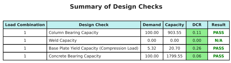
Design Summary
The SkyCiv Base Plate Design software can automatically generate a step-by-step calculation report for this design example. It also provides a summary of the checks performed and their resulting ratios, making the information easy to understand at a glance. Below is a sample summary table, which is included in the report.
SkyCiv Sample Report
See the level of detail and clarity you can expect from a SkyCiv Base Plate Design Report. The report includes all key design checks, equations, and results presented in a clear and easy-to-read format. It is fully compliant with design standards. Click below to view a sample report generated using the SkyCiv Base Plate Calculator.
Purchase Base Plate Software
Purchase the full version of the base plate design module on its own without any other SkyCiv modules. This gives you a full set of results for Base Plate Design, including detailed reports and more functionality.