Base Plate Design Example using EN 1993-1-8:2005, EN 1993-1-1:2005, EN 1992-1-1:2004, and EN 1992-4:2018.
Problem Statement
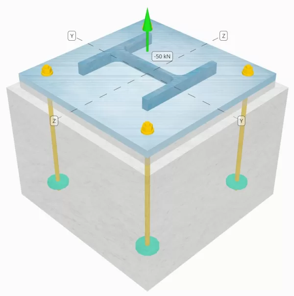
Determine whether the designed column-to-base plate connection is sufficient for a 50-kN tension load.
Given Data
Column:
Column section: HE 240 B
Column area: 10600 mm2
Column material: S235
Base Plate:
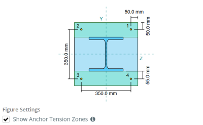
Base plate dimensions: 450 mm x 450 mm
Base plate thickness: 20 mm
Base plate material: S235
Grout:
Grout thickness: 20 mm
Concrete:
Concrete dimensions: 500 mm x 500 mm
Concrete thickness: 350 mm
Concrete material: C25/30
Cracked or Uncracked: Cracked
Anchors:
Anchor diameter: 12 mm
Effective embedment length: 300.0 mm
Embedded plate diameter: 60 mm
Embedded plate thickness: 10 mm
Anchor material: 8.8
Other information:
- Non-countersunk anchors.
- Anchor with cut threads.
Welds:
Weld type: FPBW
Filler metal classification: E35
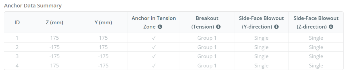
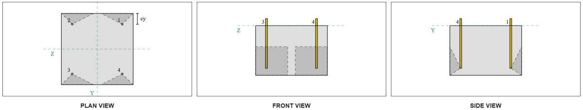
Anchor Data (from SkyCiv Calculator):
Model in SkyCiv Free Tool
Model the base plate design above using our free online tool today! No sign-up required.
Definitions
Anchor Tension Zone:
In the SkyCiv Base Plate Design Software, only anchors located within the anchor tension zone are considered effective in resisting uplift. This zone typically includes areas near the column flanges or web. Anchors outside this zone do not contribute to tension resistance and are excluded from the uplift calculations.
The assumption simplifies the base plate analysis by approximating how the uplift force spreads through the plate.
Anchor Groups:
The SkyCiv Base Plate Design Software includes an intuitive feature that identifies which anchors are part of an anchor group for evaluating concrete breakout and concrete side-face blowout failures.
An anchor group consists of multiple anchors with similar effective embedment depths and spacing, and are close enough that their projected resistance areas overlap. When anchors are grouped, their capacities are combined to resist the total tension force applied to the group.
Anchors that do not meet the grouping criteria are treated as single anchors. In this case, only the tension force on the individual anchor is checked against its own effective resistance area.
Step-by-Step Calculations
Check #1: Calculate weld capacity
From the given information, the weld used in this design example is a Full Penetration Butt Weld (FPBW). We will calculate the base metal capacities of the column and the base plate to determine the weld resistance. To do this, we first need to calculate the total weld length on the column and obtain the weld stress.
\(
F_{w,Ed} = \frac{N_x}{2 b_f t_f + \left( d_{col} – 2 t_f – 2 r_{col} \right) t_w}
\)
\(
F_{w,Ed} = \frac{50 \, \text{kN}}{2 \times 240 \, \text{mm} \times 17 \, \text{mm} + \left( 240 \, \text{mm} – 2 \times 17 \, \text{mm} – 2 \times 21 \, \text{mm} \right) \times 10 \, \text{mm}} = 5.102 \, \text{MPa}
\)
Next, we determine the tensile strength of the weaker material between the column and the base plate.
\(
f_y = \min \left( f_{y,\text{col}}, f_{y,\text{bp}} \right) = \min \left( 225 \, \text{MPa}, 225 \, \text{MPa} \right) = 225 \, \text{MPa}
\)
We then use EN 1993-1-8:2005 Clause 4.7.1 and EN 1993-1-1:2005 Eq. 6.6 to calculate the FPBW design weld resistance.
\(
F_{w,Rd3} = \frac{f_y}{\gamma_{M0}} = \frac{225 \, \text{MPa}}{1} = 225 \, \text{MPa}
\)
Since 5.102 MPa < 225 MPa, the weld capacity is sufficient.
Check #2: Calculate base plate flexural yielding capacity due to tension load
To calculate the base plate flexural capacity against tension load, we will use yield line patterns such as circular patterns and non-circular patterns. Then, we determine the governing capacity, assuming no prying forces, by comparing the plate’s yielding strength with the tensile resistance of the anchor bolts.
To start, we compute the required dimensions based on the given bolt layout. Refer to EN 1992-1-8:2005 Table 6.2 for guidance.
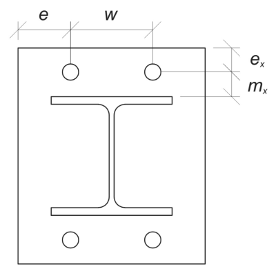
\(
m_x = \frac{s_y – d_{col}}{2} = \frac{350 \, \text{mm} – 240 \, \text{mm}}{2} = 55 \, \text{mm}
\)
\(
w = s_z \left( n_{a,\text{side}} – 1 \right) = 350 \, \text{mm} \times \left( 2 – 1 \right) = 350 \, \text{mm}
\)
\(
e_x = \frac{L_{bp} – s_y}{2} = \frac{450 \, \text{mm} – 350 \, \text{mm}}{2} = 50 \, \text{mm}
\)
\(
e = \frac{B_{bp} – w}{2} = \frac{450 \, \text{mm} – 350 \, \text{mm}}{2} = 50 \, \text{mm}
\)
\(
b_p = B_{bp} = 450 \, \text{mm}
\)
Let us also compute the anchor edge distance on the base plate, which is limited by the \( m_x \) dimension per
\(
n = \min \left( e_x, 1.25 m_x \right) = \min \left( 50 \, \text{mm}, 1.25 \times 55 \, \text{mm} \right) = 50 \, \text{mm}
\)
Then, we calculate the effective lengths ofthe following circular patterns (refer to SCI P398 Table 5.3).
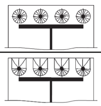
Circular pattern 1:
\(
l_{eff,cp1} = n_{a,\text{side}} \pi m_x = 2 \times \pi \times 55 \, \text{mm} = 345.58 \, \text{mm}
\)
Circular pattern 2:
\(
l_{eff,cp2} = \left( \frac{n_{a,\text{side}}}{2} \right) (\pi m_x + 2 e_x) = \left( \frac{2}{2} \right) \times (\pi \times 55 \, \text{mm} + 2 \times 50 \, \text{mm}) = 272.79 \, \text{mm}
\)
Governing circular pattern effective length:
\(
l_{eff,cp} = \min (l_{eff,cp1}, l_{eff,cp2}) = \min (345.58 \, \text{mm}, 272.79 \, \text{mm}) = 272.79 \, \text{mm}
\)
Now, we calculate the effective lengths of the following non-circular patterns (refer to SCI P398 Table 5.3)
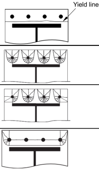
Non-circular pattern 1:
\(
l_{eff,nc1} = \frac{b_p}{2} = \frac{450 \, \text{mm}}{2} = 225 \, \text{mm}
\)
Non-circular pattern 2:
\(
l_{eff,nc2} = \left( \frac{n_{a,\text{side}}}{2} \right) (4 m_x + 1.25 e_x) = \left( \frac{2}{2} \right) \times (4 \times 55 \, \text{mm} + 1.25 \times 50 \, \text{mm}) = 282.5 \, \text{mm}
\)
Non-circular pattern 3:
\(
l_{eff,nc3} = 2 m_x + 0.625 e_x + e = 2 \times 55 \, \text{mm} + 0.625 \times 50 \, \text{mm} + 50 \, \text{mm} = 191.25 \, \text{mm}
\)
Non-circular pattern 4:
\(
l_{eff,nc4} = 2 m_x + 0.625 e_x + \frac{(n_{a,\text{side}} – 1) s_z}{2} = 2 \times 55 \, \text{mm} + 0.625 \times 50 \, \text{mm} + \frac{(2 – 1) \times 350 \, \text{mm}}{2} = 316.25 \, \text{mm}
\)
Governing non-circular pattern effective length:
\(
l_{eff,nc} = \min (l_{eff,nc1}, l_{eff,nc2}, l_{eff,nc3}, l_{eff,nc4}) = \min (225 \, \text{mm}, 282.5 \, \text{mm}, 191.25 \, \text{mm}, 316.25 \, \text{mm}) = 191.25 \, \text{mm}
\)
Then, we determine the lesser value between the effective lengths of the circular and non-circular patterns.
\(
l_{eff,1} = \min (l_{eff,cp}, l_{eff,nc}) = \min (272.79 \, \text{mm}, 191.25 \, \text{mm}) = 191.25 \, \text{mm}
\)
Now, we use this computed effective length to calculate its flexural yielding resistance. According to EN 1993-1-8:2005 Table 6.2, the plate moment resistance for failure Mode 1 is:
\(
M_{pl,1,Rd} = \frac{0.25 l_{eff,1} (t_{bp})^2 f_{y\_bp}}{\gamma_{M0}} = \frac{0.25 \times 191.25 \, \text{mm} \times (20 \, \text{mm})^2 \times 225 \, \text{MPa}}{1} = 4303.1 \, \text{kN} \cdot \text{mm}
\)
Assuming no prying, we use EN 1993-1-8:2005 Table 6.2 to determine the design resistance of the base plate for failure Modes 1 and 2.
\(
F_{T,1,Rd} = \frac{2 M_{pl,1,Rd}}{m_x} = \frac{2 \times 4303.1 \, \text{kN} \cdot \text{mm}}{55 \, \text{mm}} = 156.48 \, \text{kN}
\)
Then, we calculate the tensile resistance of the anchor rod using EN 1992-4:2018 Clause 7.2.1.3. This will be further detailed in the succeeding anchor checks.
\(
F_{t,Rd} = \frac{c k_2 F_{u\_anc} A_s}{\gamma_{M2,anchor}} = \frac{0.85 \times 0.9 \times 800 \, \text{MPa} \times 113.1 \, \text{mm}^2}{1.25} = 55.372 \, \text{kN}
\)
We will then use the resistance per anchor rod to calculate the design resistance of the base plate under failure Mode 3, which is the total bolt failure.
\(
F_{T,3,Rd} = n_{a,side} F_{t,Rd} = 2 \times 55.372 \, \text{kN} = 110.74 \, \text{kN}
\)
Finally, we determine the governing resistance value among the failure modes.
\(
F_{T,Rd} = \min (F_{T,1,Rd}, F_{T,3,Rd}) = \min (156.48 \, \text{kN}, 110.74 \, \text{kN}) = 110.74 \, \text{kN}
\)
Calculating the tension load per flange, we have:
\(
F_{T,Ed} = \frac{N_x}{2} = \frac{50 \, \text{kN}}{2} = 25 \, \text{kN}
\)
Since 25 kN < 110.74 kN, the base plate flexural yielding capacity is sufficient.
Check #3: Calculate anchor rod tensile capacity
We already know the value for the anchor rod tensile capacity, but let’s tackle it in more detail.
First, let’s calculate the tensile stress area of the anchor rod.
\(
A_s = \frac{\pi}{4} (d_{anc})^2 = \frac{\pi}{4} \times (12 \, \text{mm})^2 = 113.1 \, \text{mm}^2
\)
Then, let’s apply the values for the \( c \) factor and the \( k_{2} \) factor. These values can be modified in the settings of the SkyCiv Base Plate Design software. Try free version here.
- \( c = 0.85 \) for anchors with cut threads
- \( k_{2} = 0.9\) for non-countersunk anchor
Now, let’s use EN 1992-4:2018 Clause 7.2.1.3 to calculate the design resistance of anchor rod in tension.
\(
N_{Rd,s} = \frac{c k_2 F_{u\_anc} A_s}{\gamma_{M2,anchor}} = \frac{0.85 \times 0.9 \times 800 \, \text{MPa} \times 113.1 \, \text{mm}^2}{1.25} = 55.372 \, \text{kN}
\)
Calculating the tension load per anchor, we have:
\(
N_{Ed} = \frac{N_x}{n_{a,t}} = \frac{50 \, \text{kN}}{4} = 12.5 \, \text{kN}
\)
Since 12.5 kN < 55.372 kN, the anchor rod tensile capacity is sufficient.
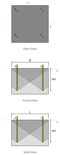
Check #4: Calculate concrete breakout capacity in tension
Before calculating the breakout capacity, we must first determine whether the member qualifies as a narrow member. According to EN 1992-4:2008 Clause 7.2.1.4(8), the member meets the criteria for a narrow member. Therefore, a modified effective embedment length must be used in the breakout capacity calculations. This adjustment also affects the characteristic spacing and characteristic edge distance, which must be modified accordingly.
Based on the narrow member criteria, the modified values for the anchor group are as follows:
- modified effective embedment length, \( h’_{ef} = 100 mm \)
- modified characteristic spacing, \( s’_{cr} = 300 mm\)
- modified characteristic edge distance, \( c’_{cr} = 150 mm\)
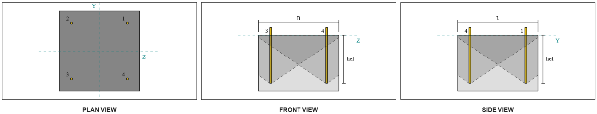
Using EN 1992-4:2018 Eq. 7.3, we calculate the reference projected concrete cone area for a single anchor.
\(
A0_{c,N} = s’_{cr,g1} s’_{cr,g1} = 350 \, \text{mm} \times 350 \, \text{mm} = 122500 \, \text{mm}^2
\)
Similarly, we calculate the actual projected concrete cone area of the anchor group.
\(
A_{Nc} = L_{Nc} B_{Nc} = 500 \, \text{mm} \times 500 \, \text{mm} = 250000 \, \text{mm}^2
\)
Where,
\(
L_{Nc} = \min \left( c_{left,g1}, c’_{cr,g1} \right)
+ \left( \min \left( s_{sum,z,g1}, s’_{cr,g1} \left( n_{z,g1} – 1 \right) \right) \right)
+ \min \left( c_{right,g1}, c’_{cr,g1} \right)
\)
\(
L_{Nc} = \min \left( 75 \, \text{mm}, 175 \, \text{mm} \right)
+ \left( \min \left( 350 \, \text{mm}, 350 \, \text{mm} \times (2 – 1) \right) \right)
+ \min \left( 75 \, \text{mm}, 175 \, \text{mm} \right)
\)
\(
L_{Nc} = 500 \, \text{mm}
\)
\(
B_{Nc} = \min \left( c_{top,g1}, c’_{cr,g1} \right)
+ \left( \min \left( s_{sum,y,g1}, s’_{cr,g1} \left( n_{y,g1} – 1 \right) \right) \right)
+ \min \left( c_{bottom,g1}, c’_{cr,g1} \right)
\)
\(
B_{Nc} = \min \left( 75 \, \text{mm}, 175 \, \text{mm} \right)
+ \left( \min \left( 350 \, \text{mm}, 350 \, \text{mm} \times (2 – 1) \right) \right)
+ \min \left( 75 \, \text{mm}, 175 \, \text{mm} \right)
\)
\(
B_{Nc} = 500 \, \text{mm}
\)
Next, we evaluate the characteristic strength of a single anchor using EN 1992-4:2018 Eq. 7.2
\(
N0_{Rk,c} = k_1 \sqrt{\frac{f_{ck}}{\text{MPa}}} \left( \frac{h’_{ef,g1}}{\text{mm}} \right)^{1.5} N
\)
\(
N0_{Rk,c} = 8.9 \times \sqrt{\frac{25 \, \text{MPa}}{1 \, \text{MPa}}} \times \left( \frac{116.67 \, \text{mm}}{1 \, \text{mm}} \right)^{1.5} \times 0.001 \, \text{kN} = 56.076 \, \text{kN}
\)
Where,
- \(k_{1} = 8.9\) for cast-in anchors
Now, we assess the effects of geometry by calculating the necessary parameters for breakout resistance.
The shortest edge distance of the anchor group is determined as:
\(
c_{min,N} = \min \left( c_{left,g1}, c_{right,g1}, c_{top,g1}, c_{bottom,g1} \right)
= \min \left( 87.5 \, \text{mm}, 87.5 \, \text{mm}, 150 \, \text{mm}, 150 \, \text{mm} \right)
= 87.5 \, \text{mm}
\)
According to EN 1992-4:2018 Eq. 7.4, the value for the parameter accounting for distribution of stress in concrete is:
\(
\Psi_{s,N} = \min \left( 0.7 + 0.3 \left( \frac{c_{min,N}}{c’_{cr,g1}} \right), 1.0 \right)
= \min \left( 0.7 + 0.3 \times \left( \frac{75 \, \text{mm}}{175 \, \text{mm}} \right), 1 \right)
= 0.82857
\)
The shell spalling effect is accounted for using EN 1992-4:2018 Eq. 7.5, giving:
\(
\Psi_{re,N} = \min \left( 0.5 + \frac{h’_{ef,g1}}{\text{mm} \, / \, 200}, 1.0 \right)
= \min \left( 0.5 + \frac{116.67 \, \text{mm}}{1 \, \text{mm} \, / \, 200}, 1 \right)
= 1
\)
In addition, both the eccentricity factor and the compression influence factor are taken as:
\(
\Psi_{ec,N} = 1
\)
\(
\Psi_{M,N} = 1
\)
We then combine all these factors and apply AS 5216:2021 Equation 6.2.3.1 to evaluate the design concrete cone breakout resistance for the anchor group:
\(
N_{Rd,c} = \frac{N0_{Rk,c} \left( \frac{A_{Nc}}{A0_{c,N}} \right) \Psi_{s,N} \Psi_{re,N} \Psi_{ec,N} \Psi_{M,N}}{\gamma_{Mc}}
\)
\(
N_{Rd,c} = \frac{56.076 \, \text{kN} \times \left( \frac{250000 \, \text{mm}^2}{122500 \, \text{mm}^2} \right) \times 0.82857 \times 1 \times 1 \times 1}{1.5} = 63.215 \, \text{kN}
\)
The total applied tension load on the anchor group is calculated by multiplying the tension load per anchor by the number of anchors:
\(
N_{fa} = \left( \frac{N_x}{n_{a,t}} \right) n_{a,g1} = \left( \frac{50 \, \text{kN}}{4} \right) \times 4 = 50 \, \text{kN}
\)
Since 50 kN < 63.215 kN the concrete breakout capacity is sufficient.
Check #5: Calculate anchor pullout capacity
The pullout capacity of an anchor is governed by the resistance at its embedded end. To begin, we calculate the bearing area of the embedded plate, which is the net area after subtracting the area occupied by the anchor rod.
First, we compute the maximum anchor head dimension effective for pull out resistance, as per EN 1992-4:2018 Clause 7.2.1.5 Note.
\(
d_{h,\text{max}} = \min \left( b_{\text{embed\_plate}}, 6 \left( t_{\text{embed\_plate}} \right) + d_{\text{anc}} \right)
= \min \left( 60 \, \text{mm}, 6 \times (10 \, \text{mm}) + 12 \, \text{mm} \right)
= 60 \, \text{mm}
\)
Next, we calculate the net bearing area of the circular embedded plate using:
\(
A_{brg} = \frac{\pi}{4} \left( \left( d_{h,\text{max}} \right)^2 – \left( d_{\text{anc}} \right)^2 \right)
\)
\(
A_{brg} = \frac{\pi}{4} \times \left( \left( 60 \, \text{mm} \right)^2 – \left( 12 \, \text{mm} \right)^2 \right) = 2714.3 \, \text{mm}^2
\)
We then calculate the design concrete pullout resistance of cast-in anchor in tension using EN 1992-4:2018 Clause 7.2.1.5:
\(
N_{Rd,s} = \frac{k_2 A_{brg} f_{ck}}{\gamma_{Mp}}
= \frac{7.5 \times 2714.3 \, \text{mm}^2 \times 25 \, \text{MPa}}{1.5}
= 339.29 \, \text{kN}
\)
Recall the previously calculated tension load per anchor:
\(
N_{Ed} = \frac{N_x}{n_{a,t}} = \frac{50 \, \text{kN}}{4} = 12.5 \, \text{kN}
\)
Since 12.5 kN < 339.29 kN, the anchor pullout capacity is sufficient.
Check #6: Calculate side-face blowout capacity in Y-direction

Let’s consider Anchor ID #3. We begin by calculating the edge distance to the failure edge.
\(
c_{z,\text{min}} = \min \left( c_{\text{left,s3}}, c_{\text{right,s3}} \right)
= \min \left( 75 \, \text{mm}, 425 \, \text{mm} \right)
= 75 \, \text{mm}
\)
Next, we determine the edge distance to the orthogonal edge.
\(
c_{y,\text{min}} = \min \left( c_{\text{top,s3}}, c_{\text{bottom,s3}} \right)
= \min \left( 425 \, \text{mm}, 75 \, \text{mm} \right)
= 75 \, \text{mm}
\)
Using EN 1992-4:2018 Eq. 7.27, let’s calculate the reference projected area of a single fastener.
\(
A0_{c,Nb} = \left( 4 c_{z,\text{min}} \right)^2
= \left( 4 \times 75 \, \text{mm} \right)^2
= 90000 \, \text{mm}^2
\)
Since we are checking the capacity of the anchor group, let’s get the actual projected area of the anchor group using EN 1992-4:2018 Eq. 7.27.
\(
A_{Nc} = B_{c,Nb} H_{c,Nb} = 225 \, \text{mm} \times 200 \, \text{mm} = 45000 \, \text{mm}^2
\)
Where,
\(
B_{c,Nb} = 2 c_{z,\text{min}} + \min \left( 2 c_{z,\text{min}}, c_{y,\text{min}} \right)
= 2 \times 75 \, \text{mm} + \min \left( 2 \times 75 \, \text{mm}, 75 \, \text{mm} \right)
= 225 \, \text{mm}
\)
\(
H_{c,Nb} = 2 c_{z,\text{min}} + \left( \min \left( t_{\text{conc}} – h_{\text{ef}}, 2 c_{z,\text{min}} \right) \right)
= 2 \times 75 \, \text{mm} + \left( \min \left( 350 \, \text{mm} – 300 \, \text{mm}, 2 \times 75 \, \text{mm} \right) \right)
= 200 \, \text{mm}
\)
In computing the characteristic concrete blow-out strength of an individual anchor, we will use EN 1992-4:2018 Eq. 7.26.
\(
N0_{Rk,cb} = k_5 \left( \frac{c_{z,\text{min}}}{\text{mm}} \right)
\left( \sqrt{\frac{A_{\text{brg}}}{\text{mm}^2}} \right)
\left( \sqrt{\frac{f_{ck}}{\text{MPa}}} \right) N
\)
\(
N0_{Rk,cb} = 8.7 \times \left( \frac{75 \, \text{mm}}{1 \, \text{mm}} \right)
\times \left( \sqrt{\frac{2714.3 \, \text{mm}^2}{1 \, \text{mm}^2}} \right)
\times \left( \sqrt{\frac{25 \, \text{MPa}}{1 \, \text{MPa}}} \right)
\times 0.001 \, \text{kN}
\)
\(
N0_{Rk,cb} = 169.97 \, \text{kN}
\)
Then, we will get the side-face blowout parameters.
The parameter accounting for the disturbance of the distribution of stresses in concrete can be calculated from EN 1992-4:2018 Eq. 7.28.
\(
\Psi_{s,Nb} = \min \left( 0.7 + 0.3 \left( \frac{c_{y,\text{min}}}{2 c_{z,\text{min}}} \right), 1.0 \right)
= \min \left( 0.7 + 0.3 \times \left( \frac{75 \, \text{mm}}{2 \times 75 \, \text{mm}} \right), 1 \right)
= 0.85
\)
In addition, the factors for group effect and factor the influence of eccentricity are as follows:
\(
\Psi_{g,Nb} = 1
\)
\(
\Psi_{ec,N} = 1
\)
Finally, in reference to AS 5216:2021 Eq. 6.2.7 for headed anchor rods, the design concrete blow-out resistance is:
\(
N_{Rk,cb} = \frac{N0_{Rk,cb} \left( \frac{A_{Nc}}{A0_{c,Nb}} \right) \left( \Psi_{s,Nb} \right) \left( \Psi_{g,Nb} \right) \left( \Psi_{ec,N} \right)}{\gamma_{Mc}}
\)
\(
N_{Rk,cb} = \frac{169.97 \, \text{kN} \times \left( \frac{45000 \, \text{mm}^2}{90000 \, \text{mm}^2} \right) \times \left( 0.85 \right) \times \left( 1 \right) \times \left( 1 \right)}{1.5} = 48.159 \, \text{kN}
\)
Recall tension load per anchor:
\(
N_{Ed} = \frac{N_x}{n_{a,t}} = \frac{50 \, \text{kN}}{4} = 12.5 \, \text{kN}
\)
Since 12.5 kN < 48.159 kN, the concrete side-face blowout along Y-direction is sufficient.
Any other Anchor ID number can also be used and will yield the same result, since the design is symmetric.
Check #7: Calculate side-face blowout capacity in Z-direction
The same procedure is used in calculating the capacity for side-face blowout in Z-direction. Let’s consider Anchor ID #2 this time. Again, we begin by calculating the edge distance to the failure edge.
\(
c_{y,\text{min}} = \min \left( c_{\text{top},s2}, c_{\text{bottom},s2} \right)
= \min \left( 75 \, \text{mm}, 425 \, \text{mm} \right)
= 75 \, \text{mm}
\)
Next, we determine the edge distance to the orthogonal edge.
\(
c_{z,\text{min}} = \min \left( c_{\text{left},s2}, c_{\text{right},s2} \right)
= \min \left( 75 \, \text{mm}, 425 \, \text{mm} \right)
= 75 \, \text{mm}
\)
Using EN 1992-4:2018 Eq. 7.27, let’s calculate the reference projected area of a single fastener.
\(
A0_{c,Nb} = \left( 4 c_{y,\text{min}} \right)^2
= \left( 4 \times 75 \, \text{mm} \right)^2
= 90000 \, \text{mm}^2
\)
Since we are checking the capacity of the anchor group, let’s get the actual projected area of the anchor group using EN 1992-4:2018 Eq. 7.27.
\(
A_{Nc} = B_{c,Nb} H_{c,Nb}
= 225 \, \text{mm} \times 200 \, \text{mm}
= 45000 \, \text{mm}^2
\)
Where,
\(
B_{c,Nb} = 2 c_{y,\text{min}} + \min \left( 2 c_{y,\text{min}}, c_{z,\text{min}} \right)
= 2 \times 75 \, \text{mm} + \min \left( 2 \times 75 \, \text{mm}, 75 \, \text{mm} \right)
= 225 \, \text{mm}
\)
\(
H_{c,Nb} = 2 c_{y,\text{min}} + \left( \min \left( t_{\text{conc}} – h_{\text{ef}}, 2 c_{y,\text{min}} \right) \right)
= 2 \times 75 \, \text{mm} + \left( \min \left( 350 \, \text{mm} – 300 \, \text{mm}, 2 \times 75 \, \text{mm} \right) \right)
= 200 \, \text{mm}
\)
In computing the characteristic concrete blow-out strength of an individual anchor, we will use EN 1992-4:2018 Eq. 7.26.
\(
N0_{Rk,cb} = k_5 \left( \frac{c_{y,\text{min}}}{\text{mm}} \right)
\sqrt{\left( \frac{A_{brg}}{\text{mm}^2} \right)}
\sqrt{\left( \frac{f_{ck}}{\text{MPa}} \right)} \, \text{N}
\)
\(
N0_{Rk,cb} = 8.7 \left( \frac{75 \, \text{mm}}{1 \, \text{mm}} \right)
\sqrt{\left( \frac{2714.3 \, \text{mm}^2}{1 \, \text{mm}^2} \right)}
\sqrt{\left( \frac{25 \, \text{MPa}}{1 \, \text{MPa}} \right)}
\cdot 0.001 \, \text{kN}
\)
\(
N0_{Rk,cb} = 169.97 \, \text{kN}
\)
Then, we will get the side-face blowout parameters.
The parameter accounting for the disturbance of the distribution of stresses in concrete can be calculated from EN 1992-4:2018 Eq. 7.28.
\(
\Psi_{s,Nb} = \min \left( 0.7 + 0.3 \left( \frac{c_{z,\text{min}}}{2 c_{y,\text{min}}} \right), 1.0 \right)
= \min \left( 0.7 + 0.3 \times \left( \frac{75 \, \text{mm}}{2 \times 75 \, \text{mm}} \right), 1 \right)
= 0.85
\)
In addition, the factors for group effect and factor the influence of eccentricity are as follows:
\(
\Psi_{g,Nb} = 1
\)
\(
\Psi_{ec,N} = 1
\)
Finally, in reference to AS 5216:2021 Eq. 6.2.7 for headed anchor rods, the design concrete blow-out resistance is:
Recall tension load per anchor:
\(
N_{Ed} = \frac{N_x}{n_{a,t}} = \frac{50 \, \text{kN}}{4} = 12.5 \, \text{kN}
\)
Since 12.5 kN < 48.159 kN, the concrete side-face blowout along Z-direction is sufficient.
Any other Anchor ID number can also be used and will yield the same result, since the design is symmetric.
Design Summary
The SkyCiv Base Plate Design software can automatically generate a step-by-step calculation report for this design example. It also provides a summary of the checks performed and their resulting ratios, making the information easy to understand at a glance. Below is a sample summary table, which is included in the report.
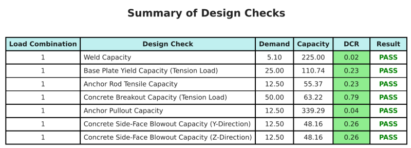
SkyCiv Sample Report
See the level of detail and clarity you can expect from a SkyCiv Base Plate Design Report. The report includes all key design checks, equations, and results presented in a clear and easy-to-read format. It is fully compliant with design standards. Click below to view a sample report generated using the SkyCiv Base Plate Calculator.
Purchase Base Plate Software
Purchase the full version of the base plate design module on its own without any other SkyCiv modules. This gives you a full set of results for Base Plate Design, including detailed reports and more functionality.