Base Plate Design Example using AS 4100:2020, AS 3600:2018, AS 5216:2021
Problem Statement
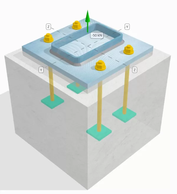
Determine whether the designed column-to-base plate connection is sufficient for a 50-kN tension load.
Given Data
Column:
Column section: 250x150x8 RHS
Column area: 5920 mm2
Column material: AS/NZS 1163 Gr. C350
Base Plate:
Base plate dimensions: 350 mm x 350 mm
Base plate thickness: 20 mm
Base plate material: AS/NZS 1163 Gr. C250
Grout:
Grout thickness: 20 mm
Concrete:
Concrete dimensions: 450 mm x 450 mm
Concrete thickness: 400 mm
Concrete material: N28
Cracked or Uncracked: Cracked
Anchors:
Anchor diameter: 16 mm
Effective embedment length: 250.0 mm
Embedded plate width: 70 mm
Embedded plate thickness: 10 mm
Anchor offset distance from face of column: 62.5 mm
Welds:
Weld type: Fillet
Weld category: SP
Filler metal classification: E43XX
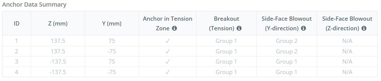
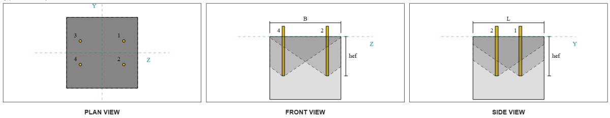
Anchor Data (from SkyCiv Calculator):
Model in SkyCiv Free Tool
Model the base plate design above using our free online tool today! No sign-up required.
Definitions
Load Path:
When a base plate is subjected to uplift (tensile) forces, these forces are transferred to the anchor rods, which in turn induce bending moments in the base plate. The bending action can be visualized as cantilever bending occurring around the flanges or web of the column section, depending on where the anchors are positioned.
In the SkyCiv Base Plate Design Software, only anchors located within the anchor tension zone are considered effective in resisting uplift. This zone typically includes areas near the column flanges or web. For rectangular columns, the anchor tension zone refers to the area adjacent to the column walls. Anchors outside this zone do not contribute to tension resistance and are excluded from the uplift calculations.
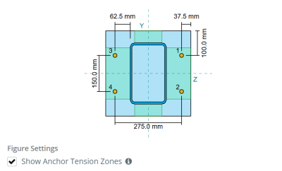
To determine the effective area of the base plate that resists bending, a 45-degree dispersion is assumed from the centerline of each anchor rod toward the column face. This dispersion defines the effective weld length and helps establish the effective bending width of the plate.
The assumption simplifies the base plate analysis by approximating how the uplift force spreads through the plate.
Anchor Groups:
The SkyCiv Base Plate Design Software includes an intuitive feature that identifies which anchors are part of an anchor group for evaluating concrete breakout and concrete side-face blowout failures.
An anchor group consists of multiple anchors with similar effective embedment depths and spacing, and are close enough that their projected resistance areas overlap. When anchors are grouped, their capacities are combined to resist the total tension force applied to the group.
Anchors that do not meet the grouping criteria are treated as single anchors. In this case, only the tension force on the individual anchor is checked against its own effective resistance area.
Prying Increase Factor:
The SkyCiv Base Plate Design Software includes an option to apply a prying increase factor to account for additional tensile forces on the anchors due to prying action. This factor increases the load demand on the anchors during the anchor checks, providing a more conservative and realistic assessment where applicable. By default, the prying increase factor is set to 1.0, meaning no additional prying load is applied unless specified by the user.
Step-by-Step Calculations:
Check #1: Calculate weld capacity
To begin, we need to calculate the load per anchor and the effective weld length per anchor. The effective weld length is determined by the shortest length from the 45° dispersion, constrained by the actual weld length and anchor spacing.
For this calculation, anchors are classified as either end anchors or intermediate anchors. End anchors are located at the ends of a row or column of anchors, while intermediate anchors are positioned between them. The calculation method differs for each and depends on the column geometry. In this example, there are two anchors along the web, and both are classified as end anchors.
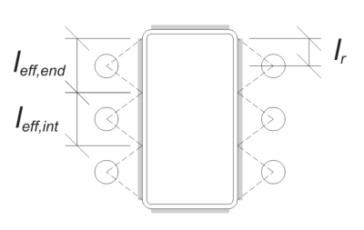
For end anchors, the effective weld length is limited by the available distance from the anchor centerline to the column corner radius. The 45° dispersion must not extend beyond this boundary.
\(
l_r = \frac{d_{col} – 2t_{col} – 2r_{col} – s_y (n_{a,\text{side}} – 1)}{2} = \frac{250 \, \text{mm} – 2 \times 8 \, \text{mm} – 2 \times 12 \, \text{mm} – 150 \, \text{mm} \times (2 – 1)}{2} = 30 \, \text{mm}
\)
On the inner side, the effective length is limited by half the anchor spacing. The total effective weld length for the end anchor is the sum of the outer and inner lengths.
\(
l_{eff,end} = \min \left( d_o, 0.5 s_y \right) + \min \left( d_o, l_r \right)
\)
\(
l_{eff,end} = \min \left( 62.5 \, \text{mm}, 0.5 \times 150 \, \text{mm} \right) + \min \left( 62.5 \, \text{mm}, 30 \, \text{mm} \right) = 92.5 \, \text{mm}
\)
For this example, the final effective weld length for the web anchor is taken as the effective length of the end anchor.
\(
l_{eff} = l_{eff,end} = 92.5 \, \text{mm}
\)
Next, let’s calculate the load per anchor. For a given set of four (4) anchors, the load per anchor is:
\(
T_{u,anchor} = \frac{N_x}{n_{a,t}} = \frac{50 \, \text{kN}}{4} = 12.5 \, \text{kN}
\)
Using the calculated effective weld length, we can now compute the required force per unit length acting on the weld.
\(
v^*_w = \frac{T_{u,anchor}}{l_{eff}} = \frac{12.5 \, \text{kN}}{92.5 \, \text{mm}} = 0.13514 \, \text{kN/mm}
\)
Now, we will use AS 4100:2020 Clause 9.6.3.10 to calculate the design strength of the fillet weld.
\(
\phi v_w = \phi 0.6 f_{uw} E_w k_r = 0.8 \times 0.6 \times 430 \, \text{MPa} \times 5.657 \, \text{mm} \times 1 = 1.1676 \, \text{kN/mm}
\)
In addition to checking the weld, we also need to verify the resistance of the base metal against the applied tension force to ensure it does not govern the failure mode.
\(
\phi v_{wbm} = \phi \left( \min \left( F_{y\_col} t_{col}, f_{y\_bp} t_{bp} \right) \right)
\)
\(
\phi v_{wbm} = 0.9 \times \left( \min \left( 350 \, \text{MPa} \times 8 \, \text{mm}, 250 \, \text{MPa} \times 20 \, \text{mm} \right) \right) = 2.52 \, \text{kN/mm}
\)
In this case, the weld resistance governs over the base metal resistance.
Since 0.13514 kN/mm < 1.1676 kN/mm, the weld capacity is sufficient.
Check #2: Calculate base plate flexural yielding capacity due to tension load
Using the load per anchor and the offset distance from the center of the anchor to the face of the column (serving as the load eccentricity), the moment applied to the base plate can be calculated using a cantilever assumption.
\(
M^* = T_{u,anchor} e = 12.5 \, \text{kN} \times 62.5 \, \text{mm} = 781.25 \, \text{kN} \cdot \text{mm}
\)
Next, using the calculated effective weld length from the previous check as the bending width, we can calculate the flexural capacity of the base plate using AISC 360-22, Equation 2-1:
\(
\phi M_s = \phi Z_{eff} f_{y\_bp} = 0.9 \times 9250 \, \text{mm}^3 \times 250 \, \text{MPa} = 2081.2 \, \text{kN} \cdot \text{mm}
\)
Where,
\(
Z_{eff} = \frac{l_{eff} (t_{bp})^2}{4} = \frac{92.5 \, \text{mm} \times (20 \, \text{mm})^2}{4} = 9250 \, \text{mm}^3
\)
Since 781.25 kN-mm < 2081.2 kN-mm, the base plate flexural yielding capacity is sufficient.
Check #3: Calculate anchor rod tensile capacity
To evaluate the tensile capacity of the anchor rod, we refer to AS 5216:2021 Clause 6.2.2 and AS 4100:2020 Clause 9.2.2.2.
First, we determine the tensile stress area of the threaded portion of the rod, following AS 4100:2020 Clause 7.2 and AS 1275–1985 Clause 1.7.
\(
A_n = \frac{\pi}{4} \left( \frac{d_a}{\text{mm}} – 0.9382 P \right)^2 \, \text{mm}^2 = \frac{\pi}{4} \times \left( \frac{16 \, \text{mm}}{1 \, \text{mm}} – 0.9382 \times 2 \right)^2 \times 1 \, \text{mm}^2 = 156.67 \, \text{mm}^2
\)
Using AS 4100:2020 Clause 9.2.2, we calculate the nominal tension capacity of the bolt based on the tensile stress area and the material strength.
\(
N_{tf} = A_n F_{u\_anc} = 156.67 \, \text{mm}^2 \times 800 \, \text{MPa} = 125.33 \, \text{kN}
\)
We then apply the appropriate resistance factor to obtain the design anchor capacity in tension.
\(
\phi N_{Rk,s} = \phi N_{tf} = 0.8 \times 125.33 \, \text{kN} = 100.27 \, \text{kN}
\)
Recall the previously calculated tension load per anchor, and apply the prying increase factor if specified.
\(
N^* = p \left( \frac{N_x}{n_{a,t}} \right) = 1 \times \left( \frac{50 \, \text{kN}}{4} \right) = 12.5 \, \text{kN}
\)
Since 12.5 kN < 100.27 kN, the anchor rod tensile capacity is sufficient.
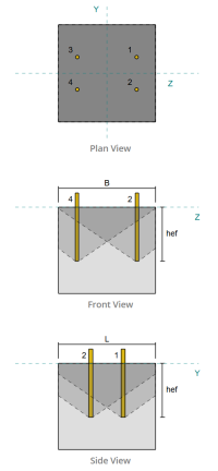
Check #4: Calculate concrete breakout capacity in tension
Before calculating the breakout capacity, we must first determine whether the member qualifies as a narrow member. According to AS 5216:2021 Clause 6.2.3.8, the member meets the criteria for a narrow member. Therefore, a modified effective embedment length must be used in the breakout capacity calculations. This adjustment also affects the characteristic spacing and characteristic edge distance, which must be modified accordingly.
Based on the narrow member criteria, the modified values for the anchor group are as follows:
- modified effective embedment length, \(h’_{ef} = 100 \, \text{mm}\)
- modified characteristic spacing, \(s’_{cr} = 300 \, \text{mm}\)
- modified characteristic edge distance, \(c’_{cr} = 150 \, \text{mm}\)
Using AS 5216: 2021 Clause 6.2.3.3, we calculate the reference projected concrete cone area for a single anchor.
\(
A0_{c,N} = \left( s’_{cr,g1} \right)^2 = \left( 300 \, \text{mm} \right)^2 = 90000 \, \text{mm}^2
\)
Similarly, we calculate the actual projected concrete cone area of the anchor group.
\(
A_{Nc} = L_{Nc} B_{Nc} = 450 \, \text{mm} \times 450 \, \text{mm} = 202500 \, \text{mm}^2
\)
Where,
\(
L_{Nc} = \min \left( c_{left,g1}, c’_{cr,g1} + r_{embed\_plate} \right) + \min \left( s_{sum,z,g1}, s’_{cr,g1} \cdot \left( n_{z,g1} – 1 \right) \right) + \min \left( c_{right,g1}, c’_{cr,g1} + r_{embed\_plate} \right)
\)
\(
L_{Nc} = \min \left( 87.5 \, \text{mm}, 150 \, \text{mm} + 18 \, \text{mm} \right) + \min \left( 275 \, \text{mm}, 300 \, \text{mm} \cdot (2 – 1) \right) + \min \left( 87.5 \, \text{mm}, 150 \, \text{mm} + 18 \, \text{mm} \right)
\)
\(
L_{Nc} = 450 \, \text{mm}
\)
\(
B_{Nc} = \min \left( c_{top,g1}, c’_{cr,g1} + r_{embed\_plate} \right) + \min \left( s_{sum,y,g1}, s’_{cr,g1} \cdot \left( n_{y,g1} – 1 \right) \right) + \min \left( c_{bottom,g1}, c’_{cr,g1} + r_{embed\_plate} \right)
\)
\(
B_{Nc} =\min \left( 150 \, \text{mm}, 150 \, \text{mm} + 18 \, \text{mm} \right) + \min \left( 150 \, \text{mm}, 300 \, \text{mm} \cdot (2 – 1) \right) + \min \left( 150 \, \text{mm}, 150 \, \text{mm} + 18 \, \text{mm} \right)
\)
\(
B_{Nc} = 450 \, \text{mm}
\)
The embedded plate effective radius is used to provide additional capacity for concrete breakout. To determine this, add the thickness of the embedded plate to half of the anchor diameter.
Next, we evaluate the characteristic strength of a single anchor using AS 5216:2021 Eq. 6.2.3.2
\(
N0_{Rk,c} = k_1 \sqrt{\frac{f’_c}{\text{MPa}}} \left( \frac{h’_{ef,g1}}{\text{mm}} \right)^{1.5} \, \text{N}
\)
\(
N0_{Rk,c} = 8.9 \times \sqrt{\frac{28 \, \text{MPa}}{1 \, \text{MPa}}} \times \left( \frac{100 \, \text{mm}}{1 \, \text{mm}} \right)^{1.5} \times 0.001 \, \text{kN} = 47.094 \, \text{kN}
\)
Where,
- \(k_{1} = 8.9\) for cast-in anchors
Now, we assess the effects of geometry by calculating the necessary parameters for breakout resistance.
The shortest edge distance of the anchor group is determined as:
\(
c_{min,N} = \min \left( c_{left,g1}, c_{right,g1}, c_{top,g1}, c_{bottom,g1} \right) = \min \left( 87.5 \, \text{mm}, 87.5 \, \text{mm}, 150 \, \text{mm}, 150 \, \text{mm} \right) = 87.5 \, \text{mm}
\)
According to AS 5216:2021 Eq. 6.2.3.4, the value for the parameter accounting for distribution of stress in concrete is:
\(
\Psi_{s,N} = \min \left( 0.7 + 0.3 \left( \frac{c_{min,N}}{c’_{cr,g1}} \right), 1.0 \right) = \min \left( 0.7 + 0.3 \times \left( \frac{87.5 \, \text{mm}}{150 \, \text{mm}} \right), 1 \right) = 0.875
\)
The shell spalling effect is accounted for using AS 5216:2021 Equation 6.2.3.5, giving:
\(
\Psi_{re,N} = \min \left( 0.5 + \frac{h’_{ef,g1}}{\text{mm} \cdot 200}, 1.0 \right) = \min \left( 0.5 + \frac{100 \, \text{mm}}{1 \, \text{mm} \cdot 200}, 1 \right) = 1
\)
In addition, both the eccentricity factor and the compression influence factor are taken as:
\(
\Psi_{ec,N} = 1
\)
\(
\Psi_{M,N} = 1
\)
We then combine all these factors and apply AS 5216:2021 Equation 6.2.3.1 to evaluate the design concrete cone breakout resistance for the anchor group:
\(
\phi N_{Rk,c} = \phi_{Mc} N0_{Rk,c} \left( \frac{A_{Nc}}{A0_{c,N}} \right) \Psi_{s,N} \Psi_{re,N} \Psi_{ec,N} \Psi_{M,N}
\)
\(
\phi N_{Rk,c} = 0.6667 \times 47.094 \, \text{kN} \times \left( \frac{202500 \, \text{mm}^2}{90000 \, \text{mm}^2} \right) \times 0.875 \times 1 \times 1 \times 1 = 61.814 \, \text{kN}
\)
The total applied tension load on the anchor group is calculated by multiplying the tension load per anchor by the number of anchors, with the prying increase factor applied as needed:
\(
N^* = p \left( \frac{N_x}{n_{a,t}} \right) n_{a,g1} = 1 \times \left( \frac{50 \, \text{kN}}{4} \right) \times 4 = 50 \, \text{kN}
\)
Since 50 kN < 61.814 kN the concrete breakout capacity is sufficient.
Check #5: Calculate anchor pullout capacity
The pullout capacity of an anchor is governed by the resistance at its embedded end. First, we compute the maximum anchor head dimension effective for pull out resistance, as per AS 5216:2021 Clause 6.3.4.
\(
d_{h,\text{max}} = \min \left( b_{embed\_plate}, 6 \left( t_{embed\_plate} \right) + d_a \right) = \min \left( 70 \, \text{mm}, 6 \times (10 \, \text{mm}) + 16 \, \text{mm} \right) = 70 \, \text{mm}
\)
Next, we calculate the net bearing area of the rectangular embedded plate using:
\(
A_h = \left( d_{h,\text{max}}^2 \right) – A_{rod} = \left( (70 \, \text{mm})^2 \right) – 201.06 \, \text{mm}^2 = 4698.9 \, \text{mm}^2
\)
Where,
\(
A_{rod} = \frac{\pi}{4} (d_a)^2 = \frac{\pi}{4} \times (16 \, \text{mm})^2 = 201.06 \, \text{mm}^2
\)
We then calculate the design basic anchor pullout strength using AS 5216:2021 Clause 6.3.4:
\(
N_{Rk,p} = \phi_{Mc} k_2 A_h \left( f’_c \right) = 0.6667 \times 7.5 \times 4698.9 \, \text{mm}^2 \times (28 \, \text{MPa}) = 657.88 \, \text{kN}
\)
Recall the previously calculated tension load per anchor:
\(
N^* = p \left( \frac{N_x}{n_{a,t}} \right) = 1 \times \left( \frac{50 \, \text{kN}}{4} \right) = 12.5 \, \text{kN}
\)
Since 12.5 kN < 657.88 kN, the anchor pullout capacity is sufficient.
Check #6: Calculate side-face blowout capacity in Y-direction
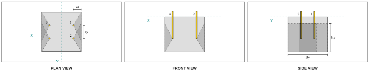
Let’s consider Side-Face Blowout Anchor Group 1 for the capacity calculation. Referring to the Anchor Data Summary, Anchor IDs 3 and 4 are part of SFy Group 1.
We begin by calculating the edge distance to the failure edge.
\(
c_{z,\text{min}} = \min \left( c_{\text{left},g1}, c_{\text{right},g1} \right) = \min \left( 87.5 \, \text{mm}, 362.5 \, \text{mm} \right) = 87.5 \, \text{mm}
\)
Next, we determine the edge distance to the orthogonal edge.
\(
c_{y,\text{min}} = \min \left( c_{\text{top},g1}, c_{\text{bottom},g1} \right) = \min \left( 150 \, \text{mm}, 150 \, \text{mm} \right) = 150 \, \text{mm}
\)
Using AS 5216:2021 Clause 6.2.7.3, let’s calculate the reference projected area of a single fastener.
\(
A0_{c,Nb} = \left( 4 c_{z,\text{min}} \right)^2 = \left( 4 \times 87.5 \, \text{mm} \right)^2 = 122500 \, \text{mm}^2
\)
Since we are checking the capacity of the anchor group, let’s get the actual projected area of the anchor group using AS 5216:2021 Clause 6.2.7.2.
\(
A_{Nc} = B_{c,Nb} H_{c,Nb} = 450 \, \text{mm} \times 325 \, \text{mm} = 146250 \, \text{mm}^2
\)
Where,
\(
B_{c,Nb} = \min \left( 2 c_{z,\text{min}}, c_{\text{top},g1} \right) + s_{\text{sum},y,g1} + \min \left( 2 c_{z,\text{min}}, c_{\text{bottom},g1} \right)
\)
\(
B_{c,Nb} = \min \left( 2 \times 87.5 \, \text{mm}, 150 \, \text{mm} \right) + 150 \, \text{mm} + \min \left( 2 \times 87.5 \, \text{mm}, 150 \, \text{mm} \right) = 450 \, \text{mm}
\)
\(
H_{c,Nb} = 2 c_{z,\text{min}} + \left( \min \left( t_{\text{conc}} – h_{\text{ef}}, 2 c_{z,\text{min}} \right) \right)
\)
\(
H_{c,Nb} = 2 \times 87.5 \, \text{mm} + \left( \min \left( 400 \, \text{mm} – 250 \, \text{mm}, 2 \times 87.5 \, \text{mm} \right) \right) = 325 \, \text{mm}
\)
In computing the characteristic concrete blow-out strength of an individual anchor, we will use AS 5216:2021 Clause 6.2.7.2.
\(
N0_{Rk,cb} = k_5 \left( \frac{c_{z,\text{min}}}{\text{mm}} \right) \sqrt{\frac{A_h}{\text{mm}^2}} \sqrt{\frac{f’_c}{\text{MPa}}} \, N
\)
\(
N0_{Rk,cb} = 8.7 \times \left( \frac{87.5 \, \text{mm}}{1 \, \text{mm}} \right) \times \sqrt{\frac{4698.9 \, \text{mm}^2}{1 \, \text{mm}^2}} \times \sqrt{\frac{28 \, \text{MPa}}{1 \, \text{MPa}}} \times 0.001 \, \text{kN}
\)
\(
N0_{Rk,cb} = 276.13 \, \text{kN}
\)
Where,
- \(k_{5} = 8.7\) for cracked concrete
- \(k_{5} = 12.2\) for uncracked concrete
Then, we will get the side-face blowout parameters.
The parameter accounting for the disturbance of the distribution of stresses in concrete can be calculated from AS 5216:2021 Clause 6.2.7.4.
\(
\Psi_{s,Nb} = \min \left( 0.7 + 0.3 \left( \frac{c_{y,\text{min}}}{2 c_{z,\text{min}}} \right), 1.0 \right)
\)
\(
\Psi_{s,Nb} = \min \left( 0.7 + 0.3 \times \left( \frac{150 \, \text{mm}}{2 \times 87.5 \, \text{mm}} \right), 1 \right) = 0.95714
\)
The equation from AS 5216:2021 Clause 6.2.7.5 is then used to get the parameter accounting for the group effect.
\(
\Psi_{g,Nb} = \max \left( \sqrt{n_{y,g1}} + \left( 1 – \sqrt{n_{y,g1}} \right) \left( \frac{\min \left( s_{y,g1}, 4 c_{z,\text{min}} \right)}{4 c_{z,\text{min}}} \right), 1.0 \right)
\)
\(
\Psi_{g,Nb} = \max \left( \sqrt{2} + \left( 1 – \sqrt{2} \right) \times \left( \frac{\min \left( 150 \, \text{mm}, 4 \times 87.5 \, \text{mm} \right)}{4 \times 87.5 \, \text{mm}} \right), 1 \right)
\)
\(
\Psi_{g,Nb} = 1.2367
\)
Finally, in reference to AS 5216:2021 Eq. 6.2.7 for headed anchor rods, the design concrete blow-out resistance is:
\(
\phi N_{Rk,cb} = \phi_M N0_{Rk,cb} \left( \frac{A_{Nc}}{A0_{c,Nb}} \right) \Psi_{s,Nb} \Psi_{g,Nb} \Psi_{ec,N}
\)
\(
\phi N_{Rk,cb} = 0.6667 \times 276.13 \, \text{kN} \times \left( \frac{146250 \, \text{mm}^2}{122500 \, \text{mm}^2} \right) \times 0.95714 \times 1.2367 \times 1 = 260.16 \, \text{kN}
\)
For this anchor group, only two (2) anchors belong to group. Therefore, the design tension force for the anchor group is:
\(
N^* = p \left( \frac{N_x}{n_{a,t}} \right) n_{y,g1}
\)
\(
N^* = 1 \times \left( \frac{50 \, \text{kN}}{4} \right) \times 2 = 25 \, \text{kN}
\)
Since 25 kN < 260.16 kN, the concrete side-face blowout along Y-direction is sufficient.
Side-Face Blowout Anchor Group 2 can also be used and will yield the same result, since the design is symmetric.
Check #7: Calculate side-face blowout capacity in Z-direction
This calculation is not applicable for failure along the Z-direction, as the edge distance to the sides exceeds half of the effective embedment length.
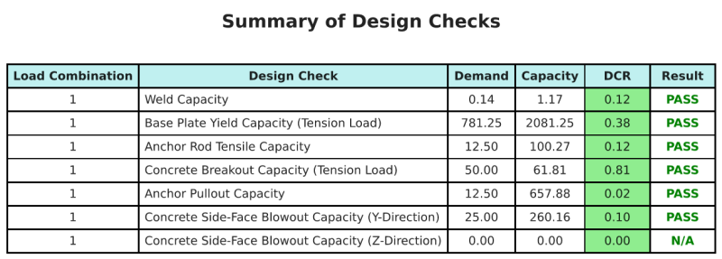
Design Summary
The SkyCiv Base Plate Design software can automatically generate a step-by-step calculation report for this design example. It also provides a summary of the checks performed and their resulting ratios, making the information easy to understand at a glance. Below is a sample summary table, which is included in the report.
SkyCiv Sample Report
See the level of detail and clarity you can expect from a SkyCiv Base Plate Design Report. The report includes all key design checks, equations, and results presented in a clear and easy-to-read format. It is fully compliant with design standards. Click below to view a sample report generated using the SkyCiv Base Plate Calculator.
Purchase Base Plate Software
Purchase the full version of the base plate design module on its own without any other SkyCiv modules. This gives you a full set of results for Base Plate Design, including detailed reports and more functionality.