Base Plate Design Example using AISC 360-22 and ACI 318-19
Problem Statement
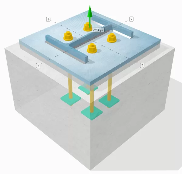
Determine whether the designed column-to-base plate connection is sufficient for a 20-kip tension load.
Given Data
Column:
Column section: W12x53
Column area: 15.6 in2
Column material: A992
Base Plate:
Base plate dimensions: 18 in x 18 in
Base plate thickness: 3/4 in
Base plate material: A36
Grout:
Grout thickness: 1 in
Concrete:
Concrete dimensions: 22 in x 22 in
Concrete thickness: 15 in
Concrete material: 4000 psi
Cracked or Uncracked: Cracked
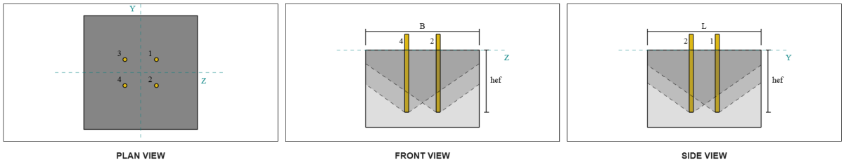
Anchors:
Anchor diameter: 3/4 in
Effective embedment length: 12 in
Embedded plate width: 3 in
Embedded plate thickness: 1/4 in
Anchor offset distance from face of column web: 2.8275 in
Welds:
Weld size: 1/4 in
Filler metal classification: E70XX
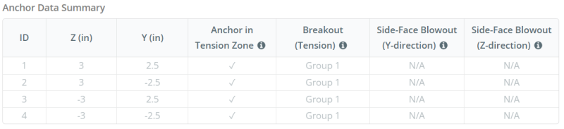
Anchor Data (from SkyCiv Calculator):
Model in SkyCiv Free Tool
Model the base plate design above using our free online tool today! No sign-up required.
Definitions
Load Path:
When a base plate is subjected to uplift (tensile) forces, these forces are transferred to the anchor rods, which in turn induce bending moments in the base plate. The bending action can be visualized as cantilever bending occurring around the flanges or web of the column section, depending on where the anchors are positioned.
In the SkyCiv Base Plate Design Software, only anchors located within the anchor tension zone are considered effective in resisting uplift. This zone typically includes areas near the column flanges or web. Anchors outside this zone do not contribute to tension resistance and are excluded from the uplift calculations.
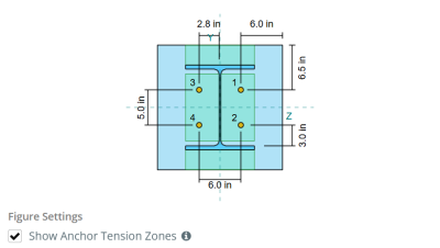
To determine the effective area of the base plate that resists bending, a 45-degree dispersion is assumed from the centerline of each anchor rod toward the column face. This dispersion defines the effective weld length and helps establish the effective bending width of the plate.
The assumption simplifies the base plate analysis by approximating how the uplift force spreads through the plate.
Anchor Groups:
The SkyCiv Base Plate Design Software includes an intuitive feature that identifies which anchors are part of an anchor group for evaluating concrete breakout and concrete side-face blowout failures.
An anchor group consists of multiple anchors with similar effective embedment depths and spacing, and are close enough that their projected resistance areas overlap. When anchors are grouped, their capacities are combined to resist the total tension force applied to the group.
Anchors that do not meet the grouping criteria are treated as single anchors. In this case, only the tension force on the individual anchor is checked against its own effective resistance area.
Step-by-Step Calculations
Check #1: Calculate weld capacity
To begin, we need to calculate the load per anchor and the effective weld length per anchor. The effective weld length is determined by the shortest length from the 45° dispersion, constrained by the actual weld length and anchor spacing.
For this calculation, anchors are classified as either end anchors or intermediate anchors. End anchors are located at the ends of a row or column of anchors, while intermediate anchors are positioned between them. The calculation method differs for each and depends on the column geometry. In this example, there are two anchors along the web, and both are classified as end anchors.
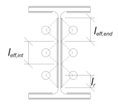
For end anchors, the effective weld length is limited by the available distance from the anchor centerline to the column fillet. The 45° dispersion must not extend beyond this boundary.
\(
l_r = \frac{d_{col} – 2t_f – 2r_{col} – s_y(n_{a,side} – 1)}{2} = \frac{12.1 \, \text{in} – 2 \times 0.575 \, \text{in} – 2 \times 0.605 \, \text{in} – 5 \, \text{in} \times (2 – 1)}{2} = 2.37 \, \text{in}
\)
On the inner side, the effective length is limited by half the anchor spacing. The total effective weld length for the end anchor is the sum of the outer and inner lengths.
\(
l_{eff,end} = \min(d_o, 0.5s_y) + \min(d_o, l_r)
\)
\(
l_{eff,end} = \min(2.8275 \, \text{in}, 0.5 \times 5 \, \text{in}) + \min(2.8275 \, \text{in}, 2.37 \, \text{in}) = 4.87 \, \text{in}
\)
For this example, the final effective weld length for the web anchor is taken as the effective length of the end anchor.
\(
l_{eff} = l_{eff,end} = 4.87 \, \text{in}
\)
Next, let’s calculate the load per anchor. For a given set of four (4) anchors, the load per anchor is:
\(
T_{u,anchor} = \frac{N_x}{n_{a,t}} = \frac{20 \, \text{kip}}{4} = 5 \, \text{kip}
\)
Using the calculated effective weld length, we can now determine the required force per unit length on the weld.
\(
r_u = \frac{T_{u,anchor}}{l_{eff}} = \frac{5 \, \text{kip}}{4.87 \, \text{in}} = 1.0267 \, \text{kip/in}
\)
Now, we will use AISC 360-22, Chapter J2.4 to calculate the design strength of the fillet weld.
Since the applied load is purely axial tension, the angle \(\theta\) is taken as 90°, and the directional strength coefficient kds is calculated according to AISC 360-22 Eq. J2-5.
\(
k_{ds} = 1.0 + 0.5(\sin(\theta))^{1.5} = 1 + 0.5 \times (\sin(1.5708))^{1.5} = 1.5
\)
Finally, we will apply AISC 360-22 Eq. J2-4 to determine the design strength of the fillet weld per unit length.
\(
\phi r_n = \phi 0.6 F_{exx} E_{w,web} k_{ds} = 0.75 \times 0.6 \times 70 \, \text{ksi} \times 0.177 \, \text{in} \times 1.5 = 8.3633 \, \text{kip/in}
\)
Since 1.0267 kpi < 8.3633 kpi, the weld capacity is sufficient.
Check #2: Calculate base plate flexural yielding capacity due to tension load
Using the load per anchor and the offset distance from the center of the anchor to the face of the column (serving as the load eccentricity), the moment applied to the base plate can be calculated using a cantilever assumption.
\(
M_u = T_{u,\text{anchor}} e = 5 \, \text{kip} \times 2.8275 \, \text{in} = 14.137 \, \text{kip} \cdot \text{in}
\)
Next, using the calculated effective weld length from the previous check as the bending width, we can calculate the flexural capacity of the base plate using AISC 360-22, Equation 2-1:
\(
\phi M_n = \phi F_{y,\text{bp}} Z_{\text{eff}} = 0.9 \times 36 \, \text{ksi} \times 0.68484 \, \text{in}^3 = 22.189 \, \text{kip} \cdot \text{in}
\)
Where,
\(
Z_{\text{eff}} = \frac{l_{\text{eff}} (t_{\text{bp}})^2}{4} = \frac{4.87 \, \text{in} \times (0.75 \, \text{in})^2}{4} = 0.68484 \, \text{in}^3
\)
Since 14.137 kip-in < 22.189 kip-in, the base plate flexural yielding capacity is sufficient.
Check #3: Calculate anchor rod tensile capacity
To evaluate the tensile capacity of the anchor rod, we will use ACI 318-19 Equation 17.6.1.2.
First, we determine the specified tensile strength of the anchor steel. This is the lowest value permitted by ACI 318-19 Clause 17.6.1.2, with reference to material properties in AISC 360-22 Table J3.2.
\(
f_{\text{uta}} = \min \left( 0.75 F_{u,\text{anc}}, 1.9 F_{y,\text{anc}}, 125 \right) = \min \left( 0.75 \times 120 \, \text{ksi}, 1.9 \times 92 \, \text{ksi}, 125.00 \, \text{ksi} \right) = 90 \, \text{ksi}
\)
Next, we calculate the effective cross-sectional area of the anchor rod. This is based on ACI 318-19 Commentary Clause R17.6.1.2, which accounts for thread geometry. The number of threads per inch is taken from ASME B1.1-2019 Table 1.
\(
A_{se,N} = \frac{\pi}{4} \left( d_a – \frac{0.9743}{n_t} \right)^2 = \frac{\pi}{4} \times \left( 0.75 \, \text{in} – \frac{0.9743}{10 \, \text{in}^{-1}} \right)^2 = 0.33446 \, \text{in}^2
\)
With these values, we apply ACI 318-19 Equation 17.6.1.2 to compute the design tensile strength of the anchor rod.
\(
\phi N_{sa} = \phi A_{se,N} f_{\text{uta}} = 0.75 \times 0.33446 \, \text{in}^2 \times 90 \, \text{ksi} = 22.576 \, \text{kip}
\)
Recall the previously calculated tension load per anchor:
\(
N_{ua} = \frac{N_x}{n_{a,t}} = \frac{20 \, \text{kip}}{4} = 5 \, \text{kip}
\)
Since 5 kip < 22.576 kip, the anchor rod tensile capacity is sufficient.
Check #4: Calculate concrete breakout capacity in tension
Before calculating the breakout capacity, we must first determine whether the member qualifies as a narrow member. According to ACI 318-19 Clause 17.6.2.1.2, the member meets the criteria for a narrow member. Therefore, a modified effective embedment length must be used in the calculations.
It is determined that the modified effective embedment length, h’ef, of the anchor group is:
\(
h’_{\text{ef}} = 5.667 \, \text{in}
\)
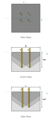
Using ACI 318-19 Clause 17.6.2, we calculate the maximum projected concrete cone area for a single anchor, based on the modified effective embedment length.
\(
A_{N_{co}} = 9 \left( h’_{ef,g1} \right)^2 = 9 \times \left( 5.6667 \, \text{in} \right)^2 = 289 \, \text{in}^2
\)
Similarly, we use the modified effective embedment length to calculate the actual projected concrete cone area of the anchor group.
\(
A_{N_c} = \min \left( n_{a,g1} A_{N_{co}}, L_{N_c} B_{N_c} \right) = \min \left( 4 \times 289 \, \text{in}^2, 22 \, \text{in} \times 22 \, \text{in} \right) = 484 \, \text{in}^2
\)
Where,
\(
L_{N_c} = \min \left( c_{\text{left},g1}, 1.5 h’_{\text{ef},g1} \right)
+ \left( \min \left( s_{\text{sum},z,g1}, 3 h’_{\text{ef},g1} \left( n_{z,g1} – 1 \right) \right) \right)
+ \min \left( c_{\text{right},g1}, 1.5 h’_{\text{ef},g1} \right)
\)
\(
L_{N_c} = \min \left( 8 \, \text{in}, 1.5 \times 5.6667 \, \text{in} \right)
+ \left( \min \left( 6 \, \text{in}, 3 \times 5.6667 \, \text{in} \times \left( 2 – 1 \right) \right) \right)
+ \min \left( 8 \, \text{in}, 1.5 \times 5.6667 \, \text{in} \right)
\)
\(
L_{N_c} = 22 \, \text{in}
\)
\(
B_{N_c} = \min \left( c_{\text{top},g1}, 1.5 h’_{\text{ef},g1} \right)
+ \left( \min \left( s_{\text{sum},y,g1}, 3 h’_{\text{ef},g1} \left( n_{y,g1} – 1 \right) \right) \right)
+ \min \left( c_{\text{bottom},g1}, 1.5 h’_{\text{ef},g1} \right)
\)
\(
B_{N_c} = \min \left( 8.5 \, \text{in}, 1.5 \times 5.6667 \, \text{in} \right)
+ \left( \min \left( 5 \, \text{in}, 3 \times 5.6667 \, \text{in} \times \left( 2 – 1 \right) \right) \right)
+ \min \left( 8.5 \, \text{in}, 1.5 \times 5.6667 \, \text{in} \right)
\)
\(
B_{N_c} = 22 \, \text{in}
\)
Next, we evaluate the basic concrete breakout strength of a single anchor using ACI 318-19 Clause 17.6.2.2.1
\(
N_b = k_c \lambda_a \sqrt{\frac{f’_c}{\text{psi}}} \left( \frac{h’_{\text{ef},g1}}{\text{in}} \right)^{1.5} \, \text{lbf}
\)
\(
N_b = 24 \times 1 \times \sqrt{\frac{4 \, \text{ksi}}{0.001 \, \text{ksi}}} \times \left( \frac{5.6667 \, \text{in}}{1 \, \text{in}} \right)^{1.5} \times 0.001 \, \text{kip} = 20.475 \, \text{kip}
\)
Where,
- \(k_{c} = 24\) for cast-in anchors
- \(\lambda = 1.0 \) for normal-weight concrete
Now, we assess the effects of geometry by calculating the edge effect factor and the eccentricity factor.
The shortest edge distance of the anchor group is determined as:
\(
c_{a,\text{min}} = \min \left( c_{\text{left},g1}, c_{\text{right},g1}, c_{\text{top},g1}, c_{\text{bottom},g1} \right)
= \min \left( 8 \, \text{in}, 8 \, \text{in}, 8.5 \, \text{in}, 8.5 \, \text{in} \right) = 8 \, \text{in}
\)
According to ACI 318-19 Clause 17.6.2.4.1, the breakout edge effect factor is:
\(
\Psi_{ed,N} = \min \left( 1.0, 0.7 + 0.3 \left( \frac{c_{a,\text{min}}}{1.5 h’_{\text{ef},g1}} \right) \right)
= \min \left( 1, 0.7 + 0.3 \times \left( \frac{8 \, \text{in}}{1.5 \times 5.6667 \, \text{in}} \right) \right) = 0.98235
\)
Since the tension load is applied at the centroid of the anchor group, the eccentricity is zero. Thus, the eccentricity factor, also from Clause 17.6.2.4.1, is:
\(
\Psi_{ec,N} = \min \left( 1.0, \frac{1}{1 + \frac{2 e’_N}{3 h’_{\text{ef},g1}}} \right)
= \min \left( 1, \frac{1}{1 + \frac{2 \times 0}{3 \times 5.6667 \, \text{in}}} \right) = 1
\)
In addition, both the cracking factor and the splitting factor are taken as:
\(
\Psi_{c,N} = 1
\)
\(
\Psi_{cp,N} = 1
\)
Then, we combine all these factors and use ACI 318-19 Eq. 17.6.2.1b to evaluate the concrete breakout strength of the anchor group:
\(
\phi N_{cbg} = \phi \left( \frac{A_{N_c}}{A_{N_{co}}} \right) \Psi_{ec,N} \Psi_{ed,N} \Psi_{c,N} \Psi_{cp,N} N_b
\)
\(
\phi N_{cbg} = 0.7 \times \left( \frac{484 \, \text{in}^2}{289 \, \text{in}^2} \right) \times 1 \times 0.98235 \times 1 \times 1 \times 20.475 \, \text{kip} = 23.58 \, \text{kip}
\)
The total applied tension load on the anchor group is the product of the individual anchor load and the number of anchors:
\(
N_{ua} = \left( \frac{N_x}{n_{a,t}} \right) n_{a,g1} = \left( \frac{20 \, \text{kip}}{4} \right) \times 4 = 20 \, \text{kip}
\)
Since 20 kips < 23.58 kips, the concrete breakout capacity is sufficient.
Check #5: Calculate anchor pullout capacity
The pullout capacity of an anchor is governed by the resistance at its embedded end. To begin, we calculate the bearing area of the embedded plate, which is the net area after subtracting the area occupied by the anchor rod.
For a rectangular embedded plate, the bearing area is calculated as:
\(
A_{brg} = \left( \left( b_{embed\_plate} \right)^2 \right) – A_{rod} = \left( \left( 3 \, \text{in} \right)^2 \right) – 0.44179 \, \text{in}^2 = 8.5582 \, \text{in}^2
\)
Where,
\(
A_{rod} = \frac{\pi}{4} \left( d_a \right)^2 = \frac{\pi}{4} \times \left( 0.75 \, \text{in} \right)^2 = 0.44179 \, \text{in}^2
\)
Next, we determine the basic anchor pullout strength using ACI 318-19 Equation 17.6.3.2.2a.
\(
N_b = 8 A_{brg} \left( f’_c \right) = 8 \times 8.5582 \, \text{in}^2 \times \left( 4 \, \text{ksi} \right) = 273.86 \, \text{kip}
\)
We then apply the appropriate resistance factor and pullout cracking factor:
- For cracked concrete, \(\Psi_{cp} = 1.0\)
- For uncracked concrete, \(\Psi_{cp} = 1.4\)
Using these, we compute the design anchor pullout strength in tension per ACI 318-19 Equation 17.6.3.1.
\(
\phi N_{pn} = \phi \Psi_{c,p} N_b = 0.7 \times 1 \times 273.86 \, \text{kip} = 191.7 \, \text{kip}
\)
Recall the previously calculated tension load per anchor:
\(
N_{ua} = \frac{N_x}{n_{a,t}} = \frac{20 \, \text{kip}}{4} = 5 \, \text{kip}
\)
Since 5 kips < 191.7 kips, the anchor pullout capacity is sufficient.
Check #6: Calculate embed plate flexural capacity
This is a supplementary check performed using the SkyCiv Base Plate Design software to verify that the embedded plate has sufficient flexural capacity and will not yield under the applied pullout loads.
First, we determine the length of the free (unsupported) end of the embedded plate, measured from the edge of the support to the face of the rod.
\(
b’ = \frac{b_{embed\_plate} – d_a}{2} = \frac{3 \, \text{in} – 0.75 \, \text{in}}{2} = 1.125 \, \text{in}
\)
Next, we calculate the bending moment induced by the uniform bearing pressure. This pressure represents the force transferred from the anchor pullout action onto the embedded plate.
\(
m_f = \frac{\left( \frac{T_a}{A_{brg}} \right) \left( b’ \right)^2}{2} = \frac{\left( \frac{5 \, \text{kip}}{8.5582 \, \text{in}^2} \right) \times \left( 1.125 \, \text{in} \right)^2}{2} = 0.36971 \, \text{kip}
\)
Finally, using the calculated moment and given material properties, we will determine the minimum required plate thickness to resist flexural yielding.
\(
t_{min} = \sqrt{\frac{4 m_f}{\phi F_{y\_ep}}} = \sqrt{\frac{4 \times 0.36971 \, \text{kip}}{0.9 \times 36 \, \text{ksi}}} = 0.21364 \, \text{in}
\)
Recall actual embedded plate thickness:
\(
t_{actual} = t_{embed\_plate} = 0.25 \, \text{in}
\)
Since 0.21364 in < 0.25 in, the embedded plate flexural capacity is sufficient.
Check #7: Calculate side-face blowout capacity in Y-direction
This calculation is not applicable for this example, as the conditions specified in ACI 318-19 Clause 17.6.4 are not met. Therefore, side-face blowout failure along the Y-direction will not occur.
Check #8: Calculate side-face blowout capacity in Z-direction
This calculation is not applicable for this example, as the conditions specified in ACI 318-19 Clause 17.6.4 are not met. Therefore, side-face blowout failure along the Z-direction will not occur.
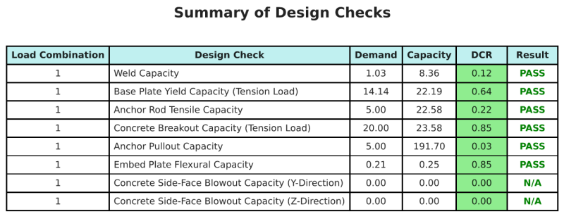
Design Summary
The SkyCiv Base Plate Design software can automatically generate a step-by-step calculation report for this design example. It also provides a summary of the checks performed and their resulting ratios, making the information easy to understand at a glance. Below is a sample summary table, which is included in the report.
SkyCiv Sample Report
See the level of detail and clarity you can expect from a SkyCiv Base Plate Design Report. The report includes all key design checks, equations, and results presented in a clear and easy-to-read format. It is fully compliant with design standards. Click below to view a sample report generated using the SkyCiv Base Plate Calculator.
Purchase Base Plate Software
Purchase the full version of the base plate design module on its own without any other SkyCiv modules. This gives you a full set of results for Base Plate Design, including detailed reports and more functionality.