Using the SkyCiv Load Generator in EN 1991-1-3 Snow Load Calculations
To calculate the snow load pressures for a structure using SkyCiv Load Generator, the process is to define first the code reference. However, only users with a Professional Account or who purchased the standalone Load Generator module will be able to use this calculation. You can purchase the standalone module thru this link.
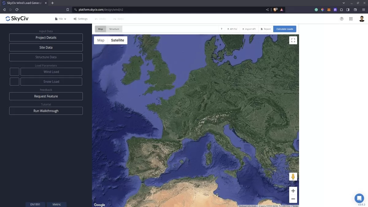
Figure 1. SkyCiv Load Generator UI.
Site Data
Using EN 1991-1-3, you need to an address in the Project Address input first and the software will automatically get the snow load for that location. Currently, the load generator supports the following countries:
- Belgium
- Denmark
- Finland
- France
- Germany
- Ireland
- Italy
- Luxembourg
- The Netherlands
- Portugal
- Romania
- Sweden
- United Kingdom
The snow load values were obtained using Appendix C of EN 1991-1-3 or each individual National Annex. To display the snow region map, you need to click “View Map Data” and then select “Snow.”
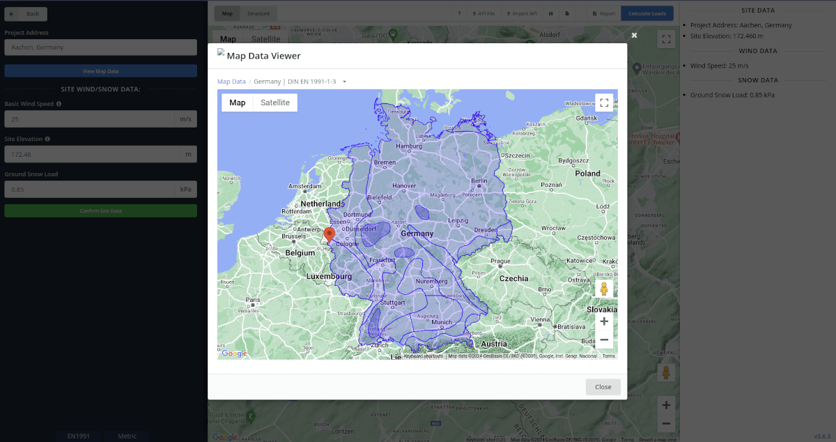
Figure 2. Snow map data of SkyCiv Load Generator.
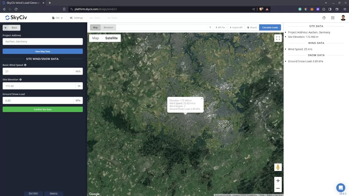
Figure 3. Site data of SkyCiv Load Generator.
SkyCiv has digitalized the map as per the paperback standard. This means, you can simply enter in the site location and the software will automatically pull the ground snow load based on this input. There is a limit to how many times the ground snow load can be obtained on the free tool.
Site Input Parameters for Snow Load Calculation
Project Address – Used for getting the nearest ground snow load based on the location
Once the parameters above are completed, we can now proceed to the Structure Data section.
Structure Data
Next step is to define first the Structure you are analyzing. Currently, only Building structure is supported in EN 1991.
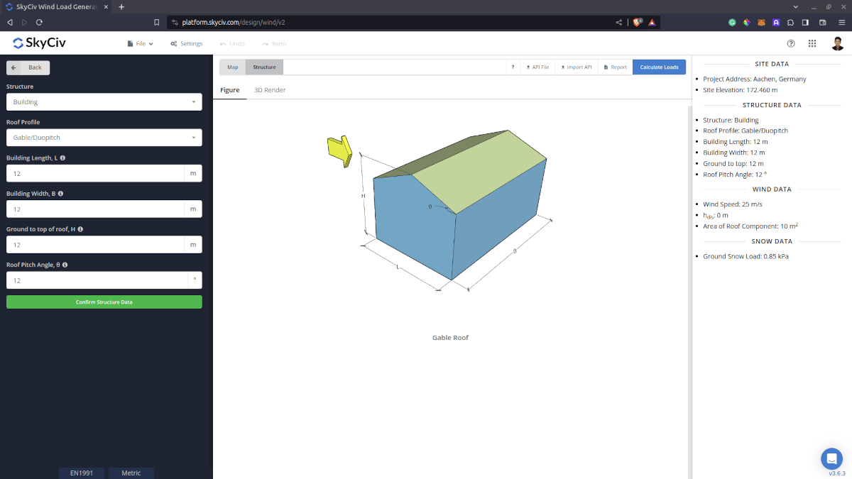
Figure 4. Structure data input for buildings.
Structure Input Parameters for Snow Load Calculation
Roof Profile – Used in pressure coefficient values based on the selected roof profile and roof pitch angle
Building Length – the dimension parallel to the wind direction as defined in EN 1991-1-4.
Building Width – the dimension perpendicular to the wind direction as defined in EN 1991-1-4.
Ground to top of roof Height – the dimension of the structure from ground to the roof apex.
Roof Pitch Angle – the roof slope in degree
Once the parameters above are completed and validated (clicking Confirm Structure Data), we can now proceed to the Snow Load Parameters section.
Snow Data
To proceed with our snow load calculation, we need to check the checkbox first beside the Snow Load button. By default, this is checked when the site snow data has been defined.
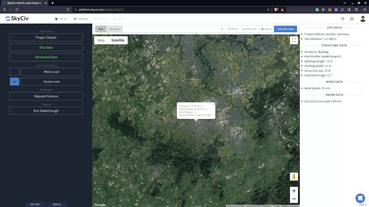
Figure 5. Checkbox for Snow Load Data.
Snow Input Parameters
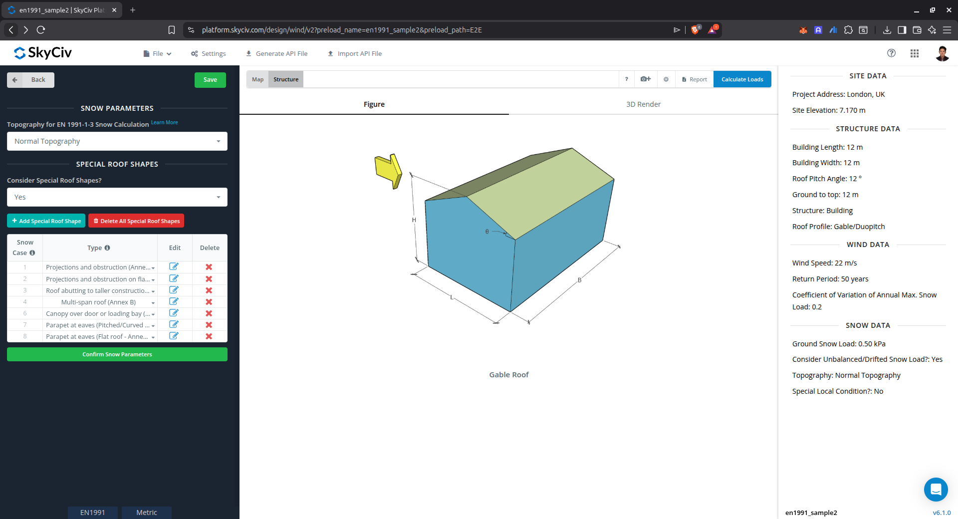
Figure 6. Snow Load Input Parameters.
Topography for EN 1991-1-3 Snow Calculation
This parameter is used in getting Exposure Coefficient Ce. The definition of each option is defined in the table below:
| Topography | Definition |
|---|---|
| Windswept | Flat unobstructed areas exposed on all sides without, or little shelter afforded by terrain, higher construction works or trees. |
| Normal | Areas where there is no significant removal of snow by wind on construction work, because of terrain, other construction works or trees. |
| Sheltered | Areas in which the construction work being considered is considerably lower than the surrounding terrain or surrounded by high trees and/or surrounded by higher construction works. |
Type of Snow
This parameter is used in getting the mean bulk weight density of snow, γ. The definition of each option is defined in the table below:
| Type of Snow | Bulk weight density kN/m3 |
|---|---|
| Fresh | 1.0 |
| Settled (several hours or days after its fall) | 2.0 |
| Old (several weeks or months after its fall) | 3.0 |
| Wet | 4.0 |
By default, this parameter is selected to the recommended snow density value based on the National Annexes.
Consider Special Load Case?
This parameter is a “Yes” or “No” to calculate Snow Load on other roof cases. Upon selecting “No,” the snow load case for the selected roof profile shall only be calculated. On the other hand, upon selecting “Yes,” the snow load for special case table will show.
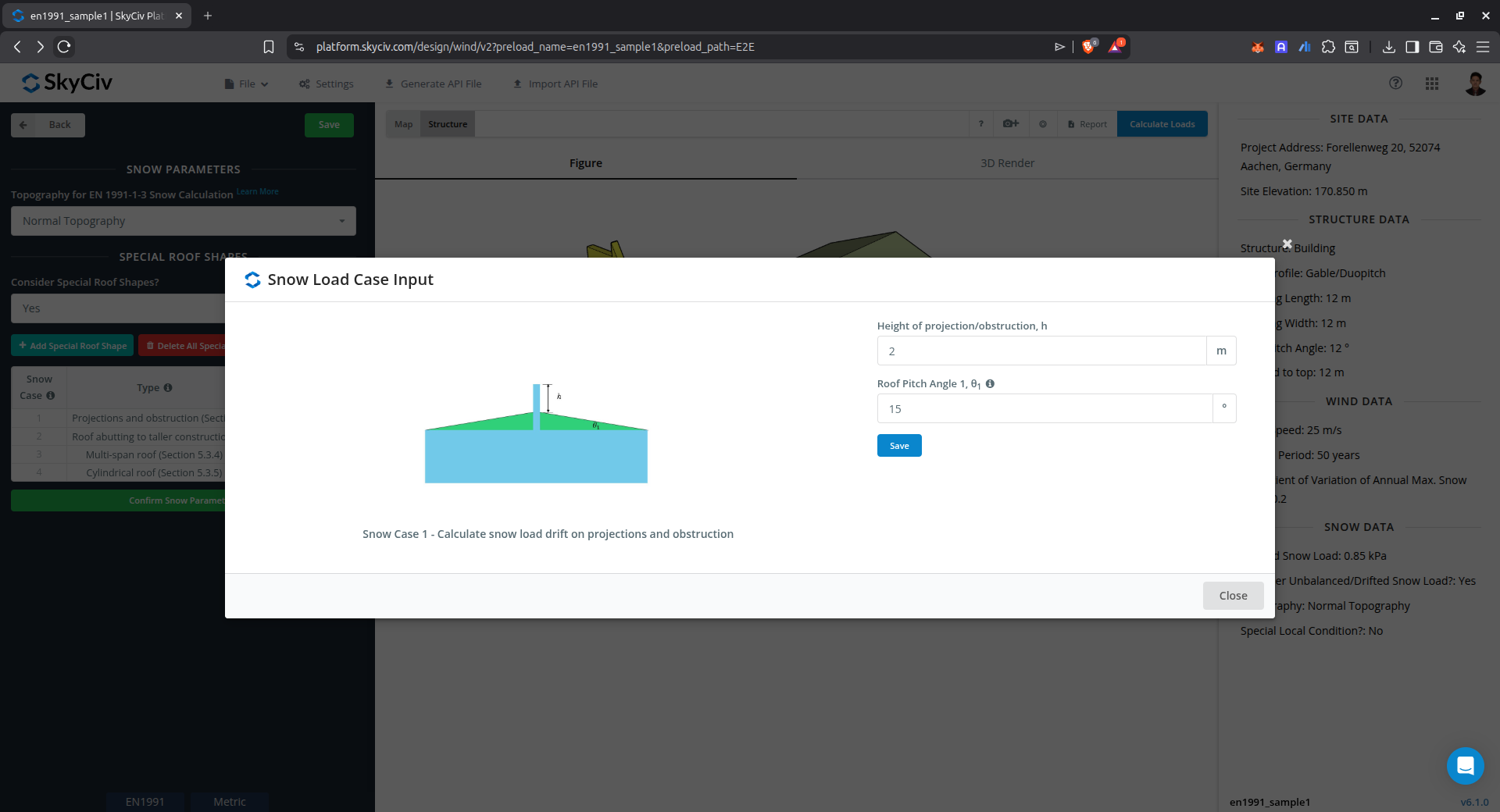
Drift on projections and obstruction
This case is used to calculate the snow load drift on obstructions above the roof level such as parapet walls, firewalls, chimneys, etc.
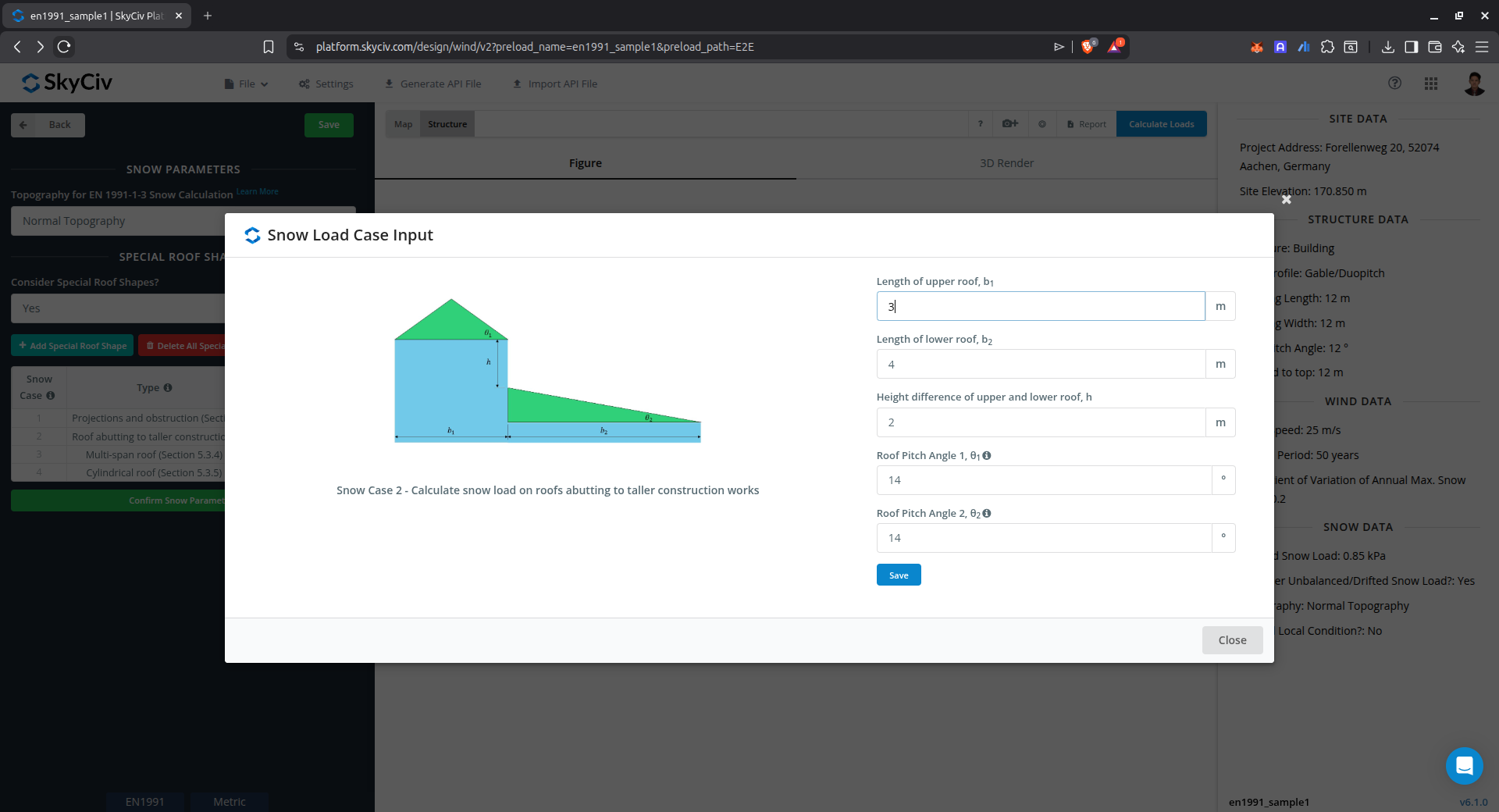
Drift on roof abutting to taller construction works
This case is used to calculate the snow load drift on roof abutting to taller construction works.
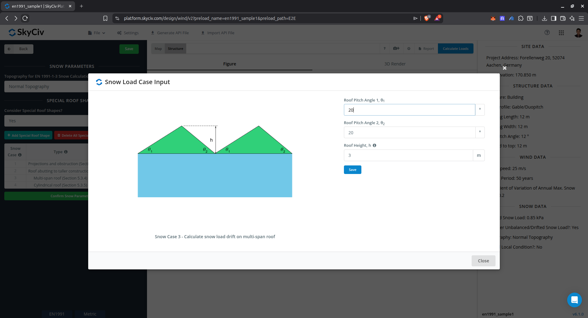
Drift on multi-span roof
This case is used to calculate the snow load drift on multiple pitched roof.
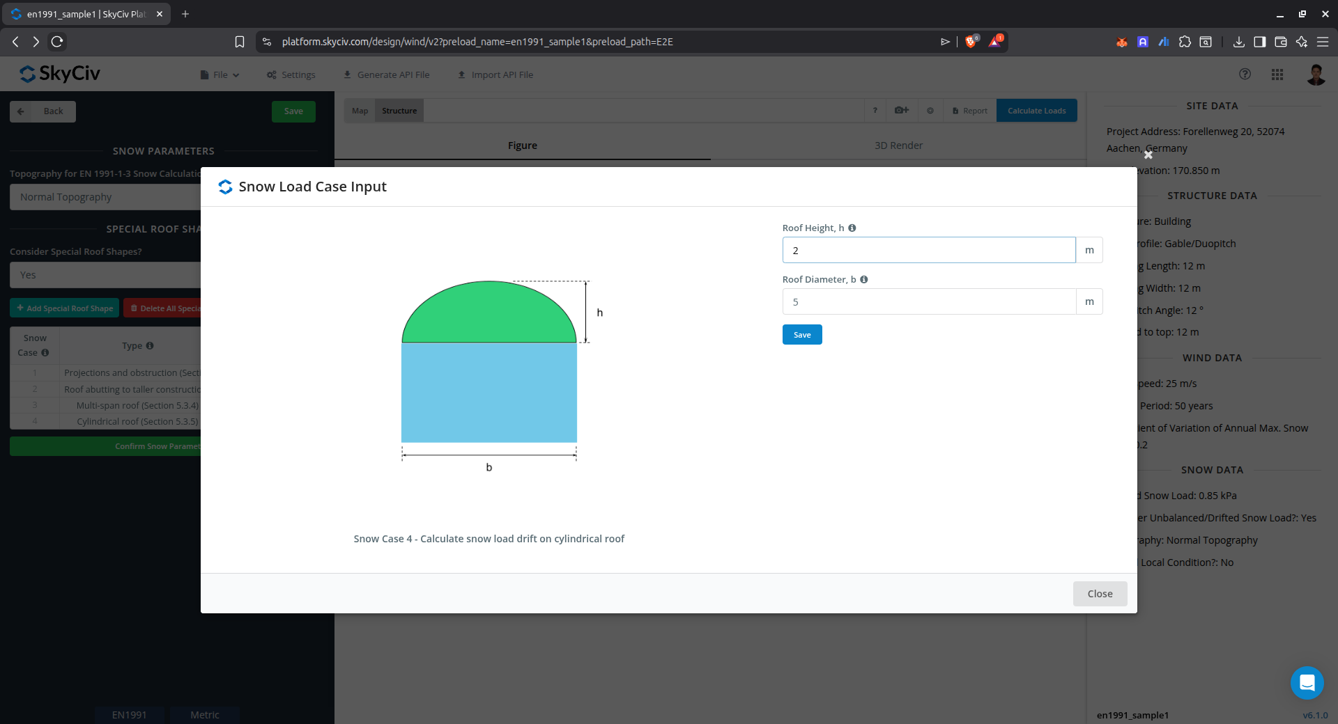
Drift on cylindrical roof
This case is used to calculate the snow load drift on cylindrical roof.
Drift on projections and obstruction (Annex B)
This case is used to calculate the snow load drift on obstructions using Annex B of EN 1991-1-3.
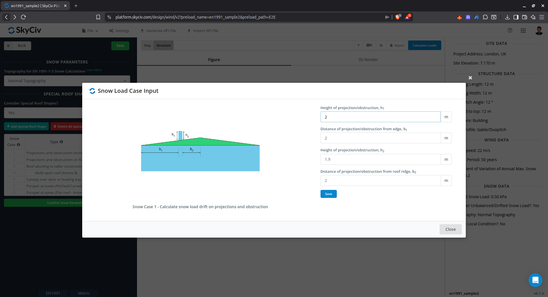
Figure 11. Parameters for calculating drifted snow load on projects and obstruction using Annex B of EN 1991-1-3.
Drift on projections and obstruction on Flat Roof (Annex B)
This case is used to calculate the snow load drift on obstructions on flat roof using Annex B of EN 1991-1-3.

Figure 12. Parameters for calculating drifted snow load on projects and obstruction on flat roof using Annex B of EN 1991-1-3.
Drift on roof abutting to taller construction works (Annex B)
This case is used to calculate the snow load drift on roof abutting to taller construction works using Annex B of EN 1991-1-3.
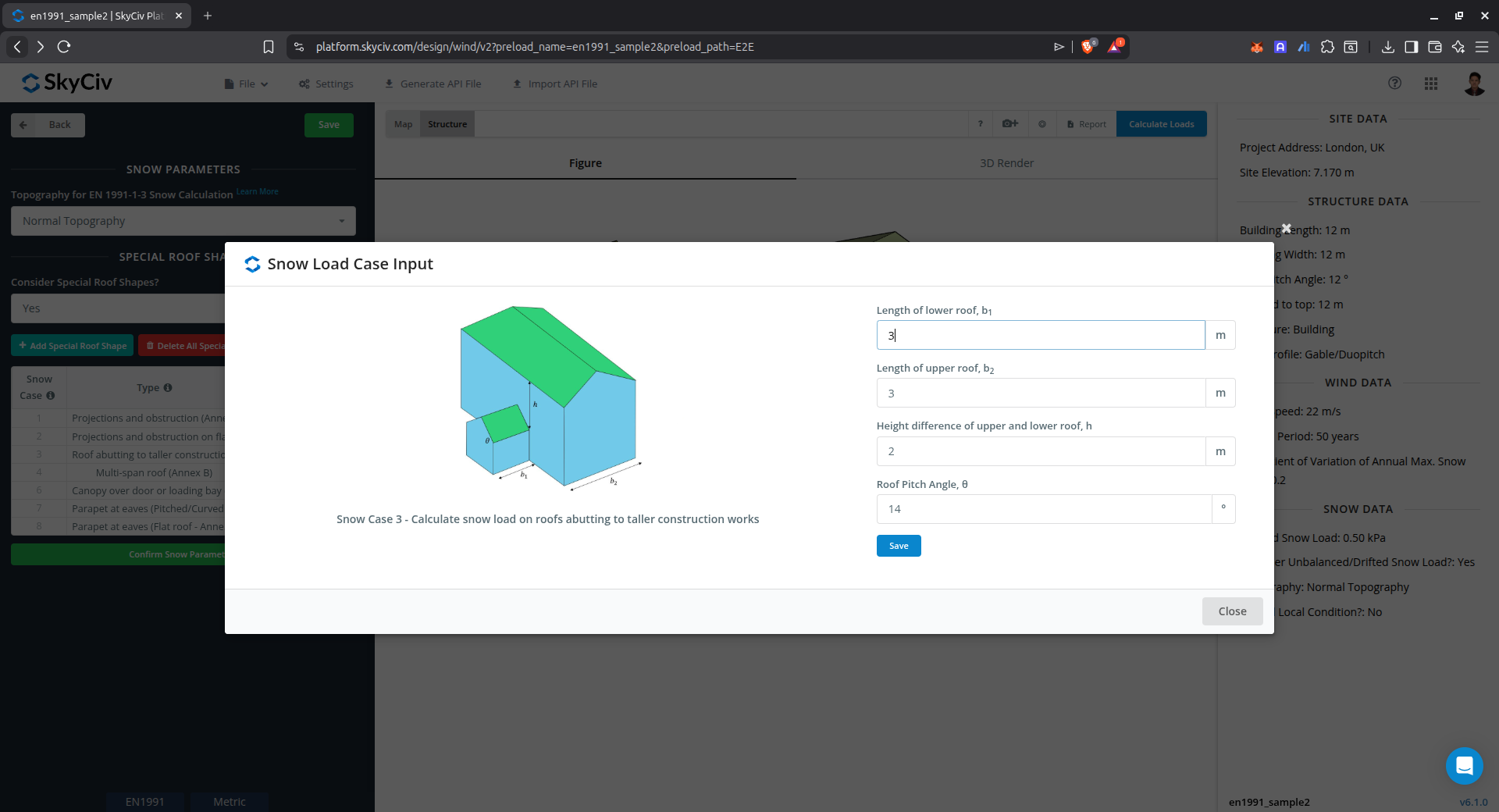
Figure 13. Parameters for calculating drifted snow load on roof abutting to taller construction works using Annex B of EN 1991-1-3.
Drift on multi-span roof (Annex B)
This case is used to calculate the snow load drift on multiple pitched roof using Annex B of EN 1991-1-3.
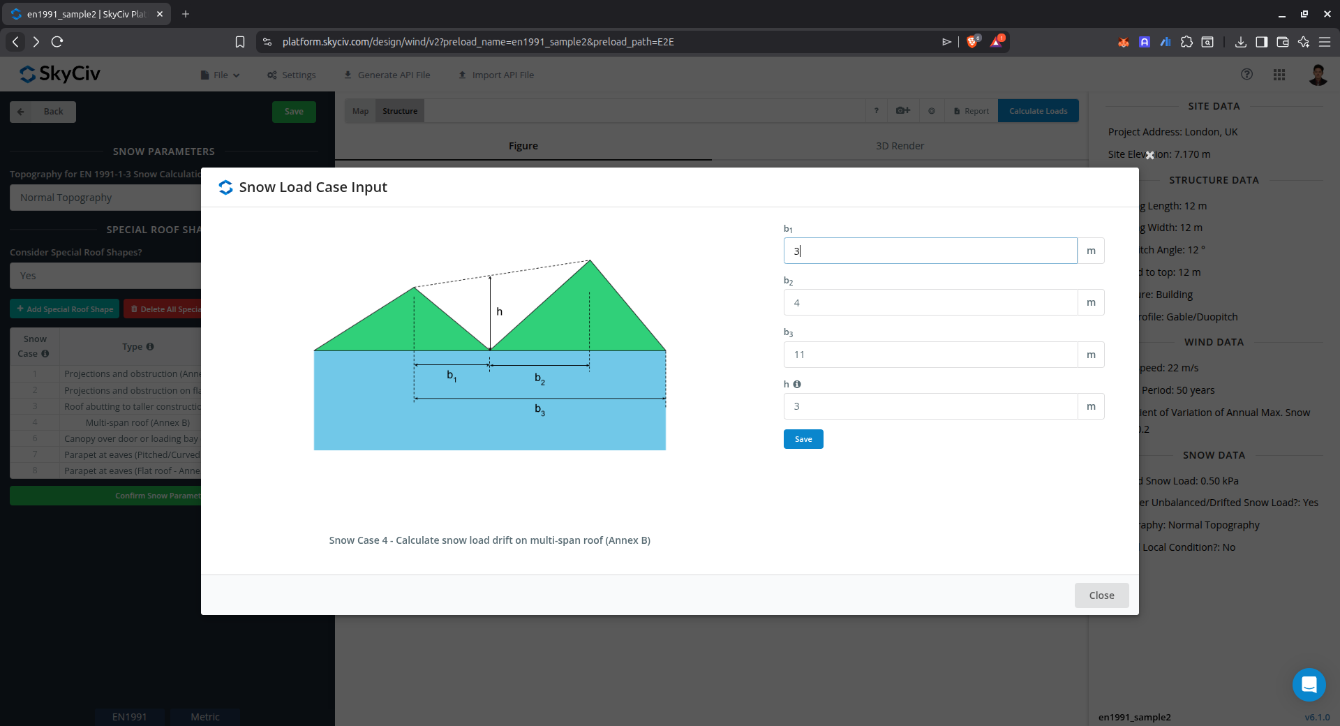
Figure 14. Parameters for calculating drifted snow load on multiple pitched roof using Annex B of EN 1991-1-3.
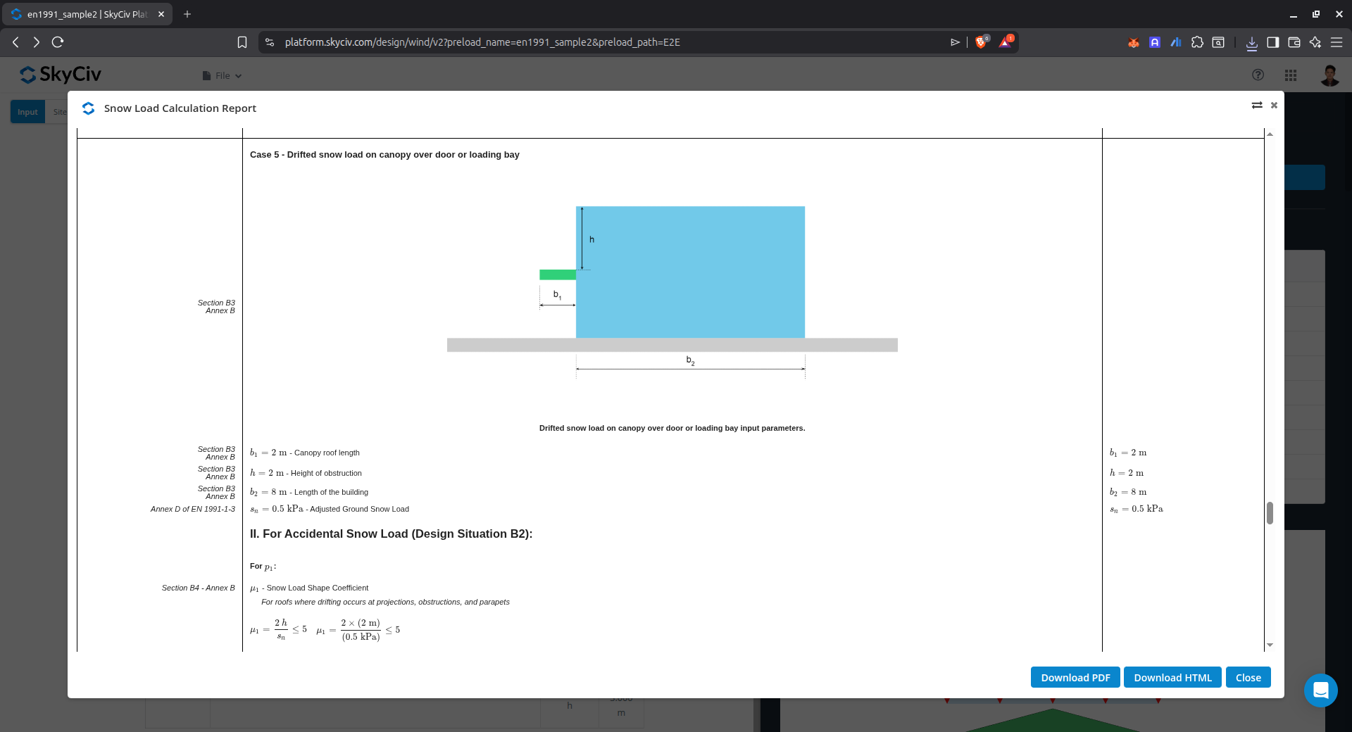
Drift on canopy over door or loading bay (Annex B)
This case is used to calculate the snow load drift on canopy over door or loading bay using Annex B of EN 1991-1-3.
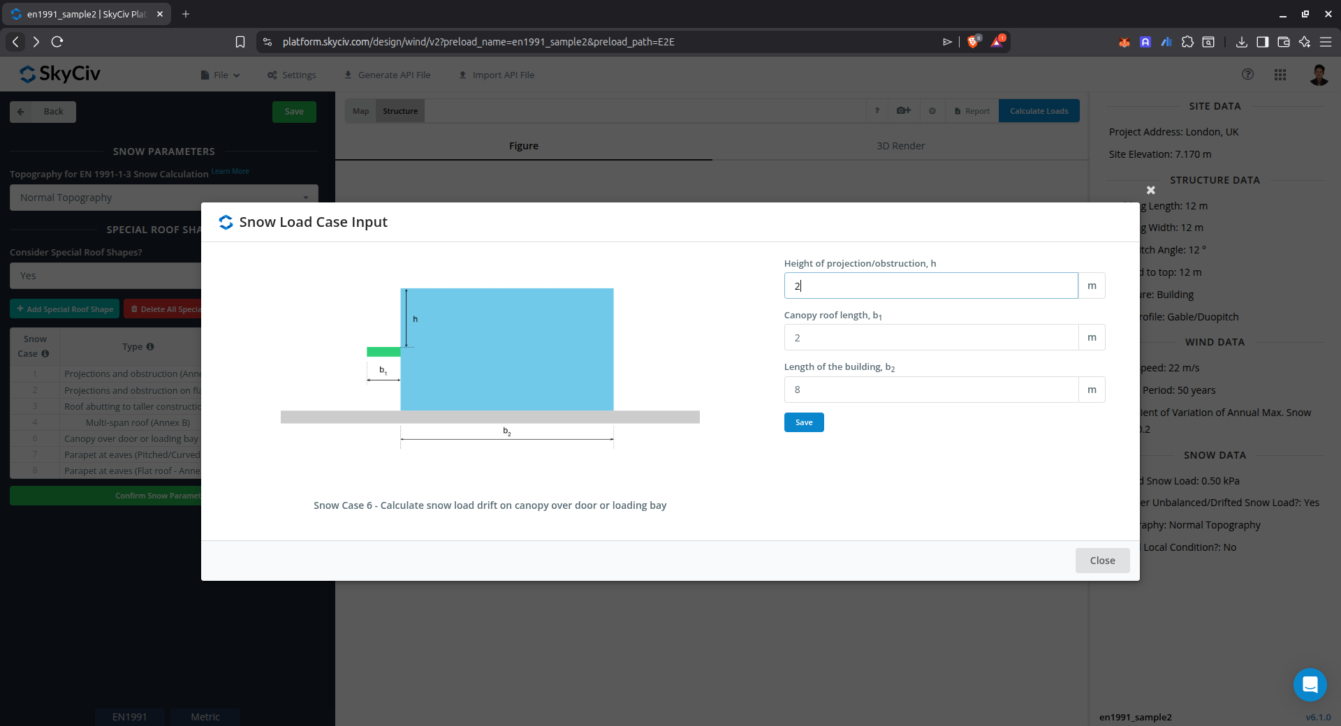
Figure 15. Parameters for calculating drifted snow load on canopy over door or loading bay using Annex B of EN 1991-1-3.
Drift on parapet at eaves of pitched/curved roof (Annex B)
This case is used to calculate the snow load drift on parapet at eaves of pitched/curved roof using Annex B of EN 1991-1-3.

Figure 16. Parameters for calculating drifted snow load on parapet at eaves of pitched/curved roof using Annex B of EN 1991-1-3.
Drift on parapet at eaves of flat roof (Annex B)
This case is used to calculate the snow load drift on parapet at eaves of flat roof using Annex B of EN 1991-1-3.
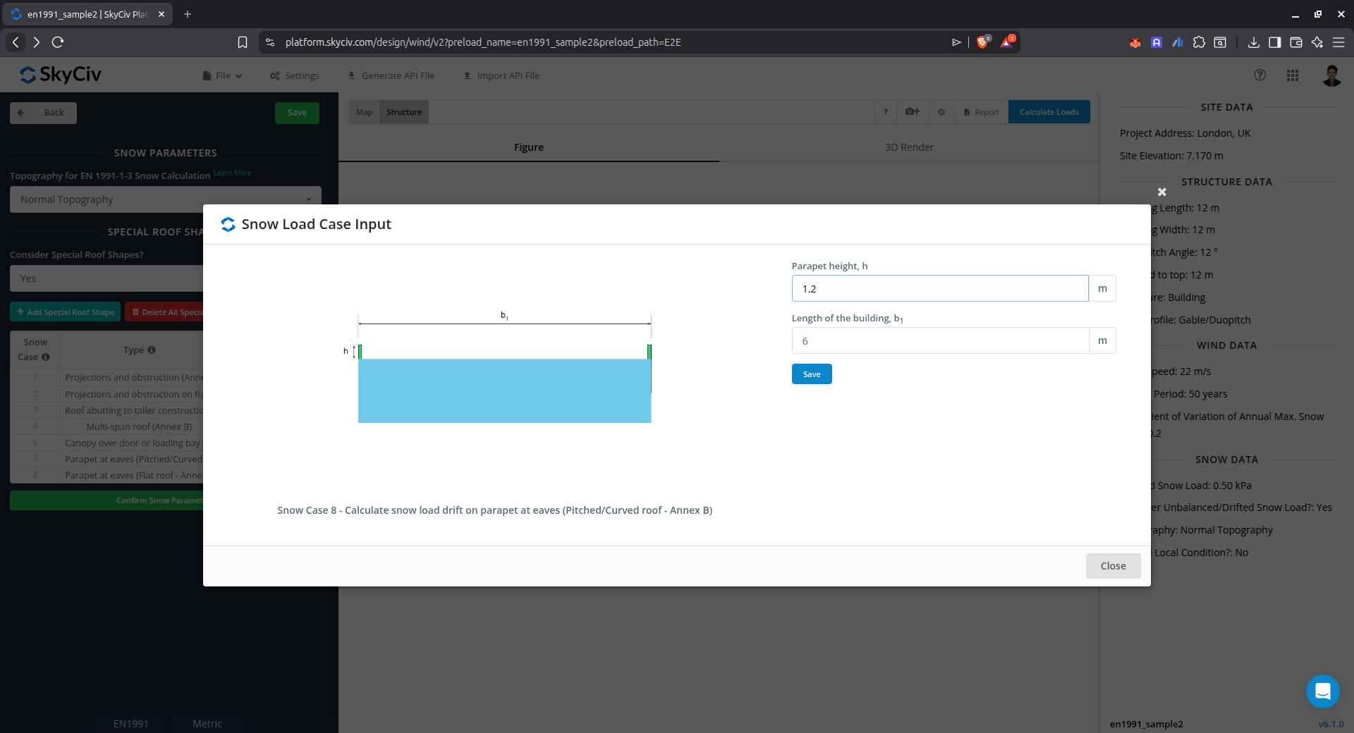
Figure 17. Parameters for calculating drifted snow load on parapet at eaves of flat roof using Annex B of EN 1991-1-3.
Results
The snow load results will show the parameters in calculating the snow load as shown below:
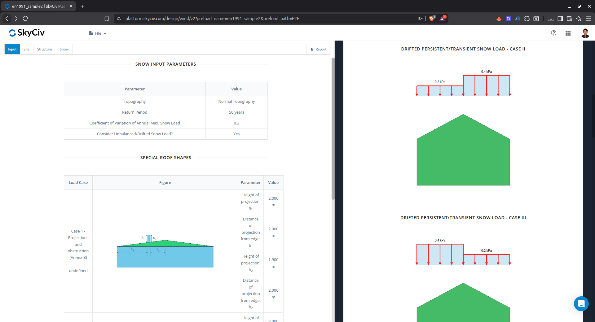
Figure 18. Snow load parameters used in the calculation and the calculated snow load for the selected roof profile.
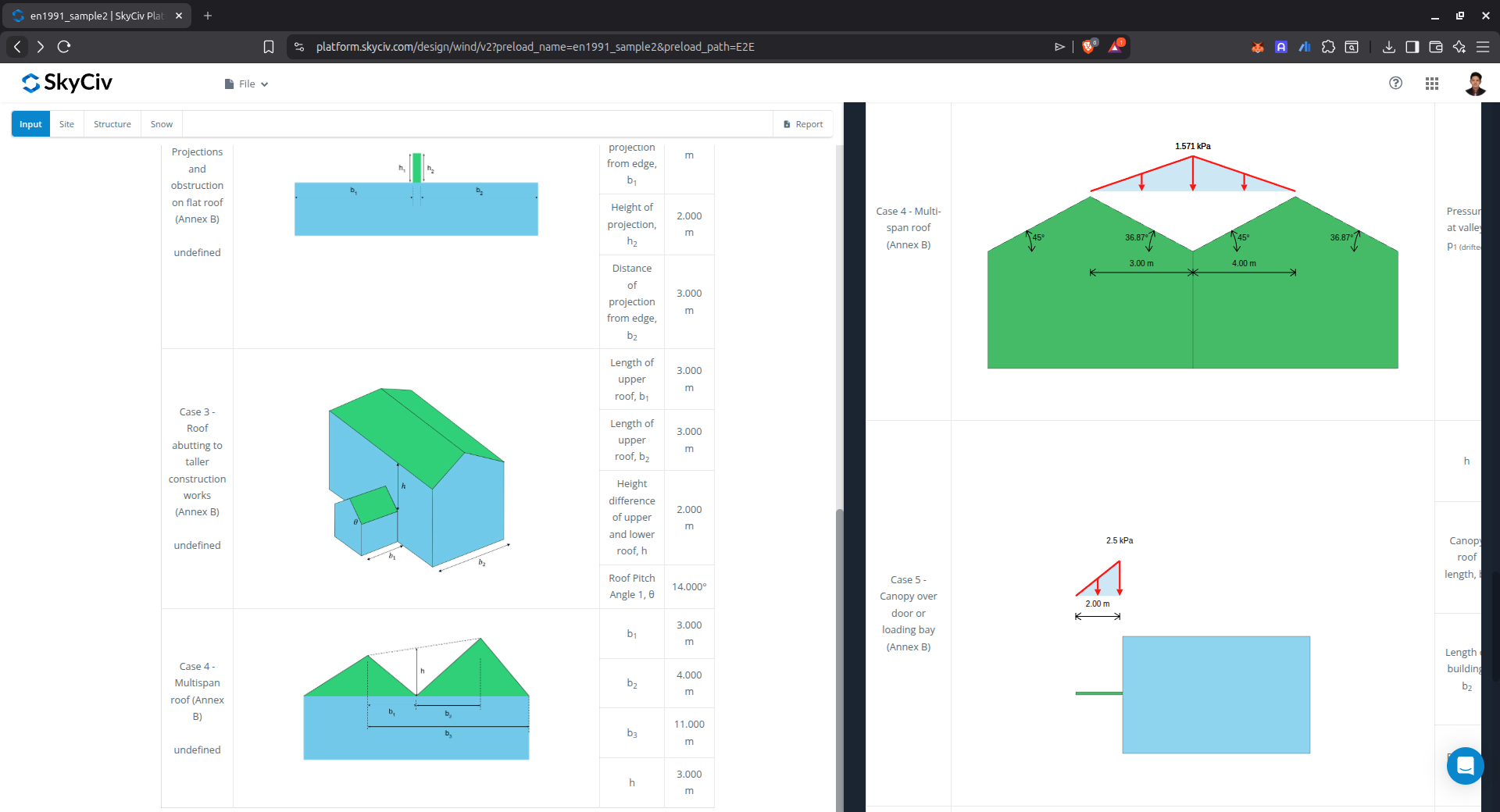
Figure 19. Drifted snow load results for special roof cases.
Detailed Calculation
The detailed snow load calculations can be accessed only by Professional account users and those who purchased the standalone load generator module. All the parameters and assumptions used in the calculation are displayed on the report to make it transparent to the user. You can download a sample detailed calculation thru the following links: