AISC Base Plate Design Example American Code
Below is an example of some American Base Plate Calculations that are commonly used in base plate design. Often when designing base plates, we will consider a few different checks relating to the various components of a base plate, namely:
- The Concrete base – generally checked against bearing and compression forces in reference to ACI 318
- The Welds – welds need to be checked, to ensure they provide adequate restraint and do not fail under stress to AISC 360
- Anchor Bolts – can fail due to a number of reasons, as shown below in the example anchor bolt design calculations to AISC
- Steel Member (Column) checks – usually based on local steel design standards
Currently, the Steel Base Plate Design module implements the following checks below. The paid version of this software, includes detailed step-by-step calculations, so that engineers can review exactly how these calculations are made!
Try this calculation using SkyCiv Free Base Plate Calculator:
Load Combinations:
The Steel Base Plate Design the uses factored load combinations under ASCE 7-10/16 applies as follows:
- \(1.4D\)
- \(1.2D + 1.6L + 0.5(L_{r} \text{ or } S \text{ or } R)\)
- \(1.2D + 1.6(Lr \text{ or } S \text{ or } R) + (L \text{ or } 0.5W)\)
- \(1.2D + 1.0W + L + 0.5(Lr \text{ or } S \text{ or } R)\)
- \(1.2D + 1.0E + L + 0.2S\)
- \(0.9D + 1.0W\)
- \(0.9D + 1.0E\)
where :
\(D\) = dead load
\(L\) = live load
\(L_{r}\) = roof live load
\(S\) = Snow load
\(R\) = Rain load
\(E\) = Earthquake
\(W\) = Wind load
Try this calculation using SkyCiv Free Base Plate Calculator:
ACI Concrete bearing check:
The Steel Base Plate Design checks the Concrete bearing strength (compression) design in according to AISC 360-16 Eq. J8-2.
\( F_{b} = \phi _{bearing} \times 0.85 \times f’_{c} \times \sqrt{ \frac{ A_{2} }{ A_{1} } } \leq F_{b, limit} = 1.70 \times f_{c} \times A_{1} \)
where:
\( f’_{c} \) – concrete compressive strength
\( A_{1} \) – base plate area in contact with concrete surface
\( A_{2} \) – concrete supporting surface
\( \phi_{bearing} \) – resistance factor for concrete ( default value= 0.65 )
Try this calculation using SkyCiv Free Base Plate Calculator:
AISC Weld Design Check:
The Steel Base Plate Design checks weld design accordance to AISC 360-16 J2
\( (i) R_{n} = R_{nwl} + R_{nwt} \)
or
\( (ii) R_{n} = 0.85R_{nwl} + 1.5R_{nwt} \)
where:
\(R_{nwl} \) = total nominal strength of longitudinal loaded fillet welds.
\(R_{nwt} \) = total nominal strength of transversely loaded fillet welds.
Try this calculation using SkyCiv Free Base Plate Calculator:
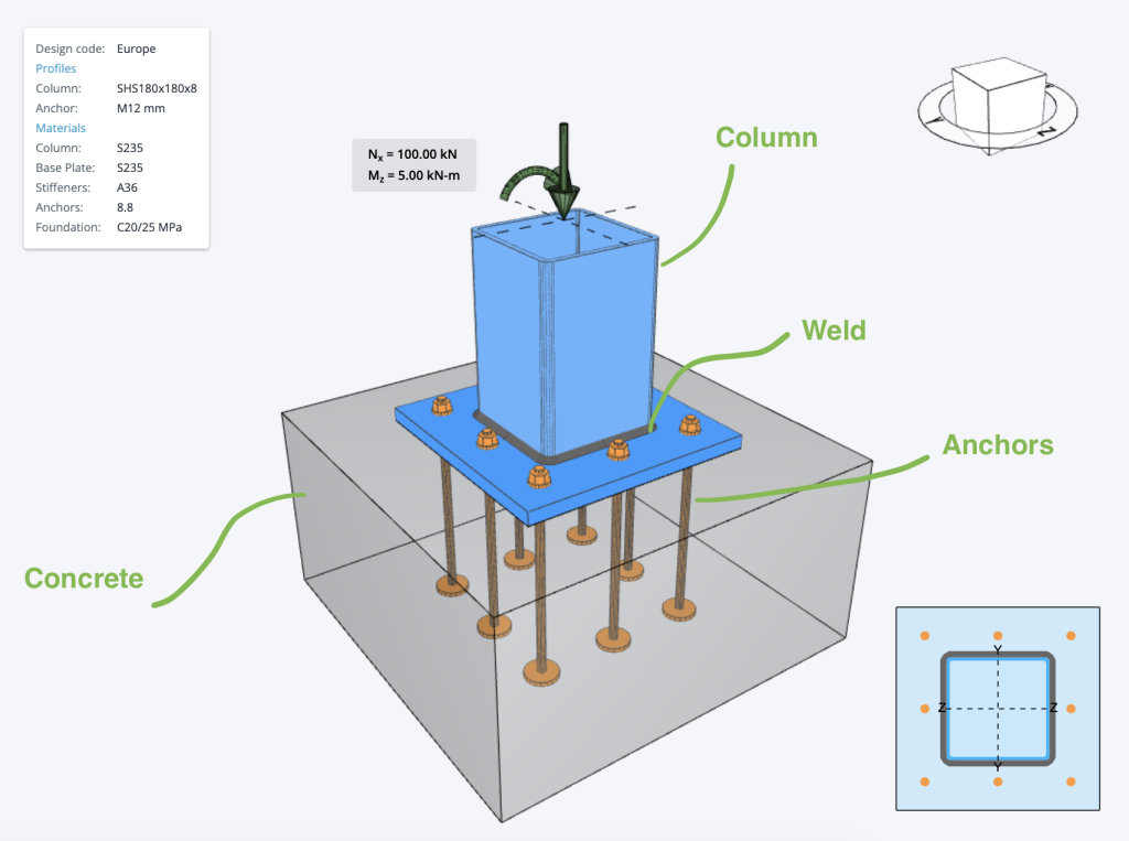
ACI Anchor Design Check:
The Steel Base Plate Design checks Anchor parameters applies using code provisions of ACI 318-19 under Chapter 17.
Anchor rods are designed according to AISC 360-16 – J9 and ACI 318-19 – Chapter 17. The following resistances of anchor bolts are evaluated:
- Steel strength of anchor in tension and shear, \( \phi N_{sa} \) and \( \phi V_{sa} \).
- Concrete breakout strength in tension and shear, \( \phi N_{cbg} \) and \( \phi V_{cbg} \).
- Concrete pullout strength, \( \phi N_{p} \).
- Concrete side-face blowout strength, \( \phi N_{sb} \).
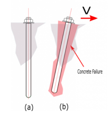
- Concrete pryout strength of anchor in shear, \( \phi V_{cp} \).
Steel strength of anchor in tension and shear
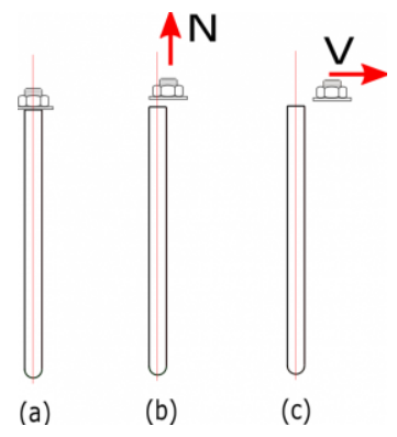
Figure A. (a) unbreakout bolt (b) bolt break-out due to tension failure (c) bolt split-out due to shear failure
Factored steel strength of anchor in tension and shear is determined according to ACI 318-19 – 17.6.1.2 and 17.7.1 as
For Tension
\( \phi _{tension, anc} N_{sa} = \phi _{tension, anc} A_{se,N}f_{uta} \rightarrow \) equation 17.6.1.2
For Shear
\( \phi _{shear, anc} V_{sa} = \phi _{shear, anc} 0.6A_{se,V}f_{uta} \rightarrow \) equation 17.7.1.2b
where:
- \( \phi _{tension, anc} \) – strength reduction factor for anchors in tension ( default value = 0.75 )
- \( \phi _{shear, anc}\) – strength reduction factor for anchors in shear ( default value = 0.65 )
- \( A_{se,N}\) – is the effective cross-sectional area of an anchor in tension.
- \( A_{se,V}\) – is the effective cross-sectional area of an anchor in shear.
- \( f_{uta}\) – specified tensile strength of anchor steel and shall not be greater than \(1.9f_{ya}\) and 125 ksi (861.845 Mpa)
Concrete breakout strength
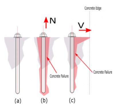
Figure B. (a) Bolt rest at concrete (b) concrete break-out due to tension force (c) concrete break-out due to shear force
Factored concrete breakout strength of anchor in tension and shear is determined according to ACI 318-19 – 17.6.2 and 17.7.1 as
\( \phi N_{cbg} = \phi \frac{ A_{Nc} }{ A_{Nco} } \psi_{ec,N} \psi_{ed,N} \psi_{c,N} \psi_{cp,N} N_{b} \rightarrow \) equation 17.6.2.ab
where:
\( \phi \) – strength reduction factor for anchors in tension ( default value = 0.75 ).
\( A_{Nc} \) – projected concrete failure of a single or group anchors.
\( A_{Nco} \)- project concrete failure area of a single anchor, for calculation of strength in tension if not limited by edge distance or spacing.
\( \psi_{ec,N} \) – Breakout eccentricity factor in tension.
\( \psi _{ec,N} = \frac{1.00}{ 1 + \frac{e^{‘}_{N}}{1.5 h_{ef}} } \leq 1.00 \rightarrow \) equation 17.6.2.3.1
\( \psi_{ed,N} \) – Breakout effect factor in tension.
(a) \( \text{if } C_{a,min} \geq 1.5h_{ef} \text{ then } \psi _{ed,N} = 1.00 \) equation 17.6.2.4.1a
and
(b) \( \text{if } C_{a,min} < 1.5h_{ef} \text{ then } \psi _{ed,N} = 0.70 + 0.3\frac{C_{a,min}}{1.5h_{ef}} \) equation 17.6.2.4.1b
\( \psi_{c,N} \) – Breakout cracking factor in tension.
\( \psi _{c,N} = 1.25 \) for cast-in anchors
\( \psi_{cp,N} \) – Breakout splitting factor in tension.
(a) \( \text{if } C_{a,min} \geq C_{ac} \text{ then } \psi _{cp,N} = 1.00 \) equation 17.6.2.4.1a
and
(b) \( \text{if } C_{a,min} < C_{ac} \text{ then } \psi _{cp,N} = \frac{ C_{a,min} }{ C_{ac}} \geq \frac{ 1.5h_{ef} }{ C_{ac} } \) equation 17.6.2.4.1b
\( N_{b} \) – basic concrete breakout strength in tension of a single anchor in cracked concrete.
Concrete pullout strength
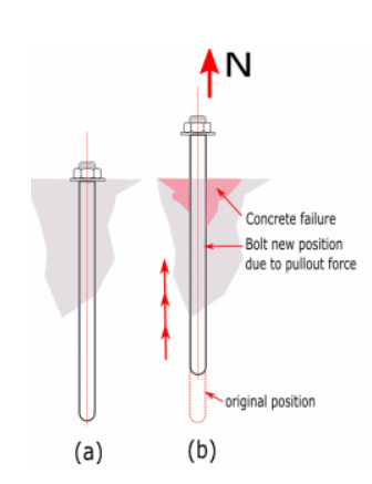
Figure C. (a) Bolt rest at concrete (b) bolt pull-off from concrete due to tension force
Factored concrete pullout strength of an anchor is defined in ACI 318-19 – 17.6.3 as
ϕNpn = ϕΨc,P Np
where:
\( \phi \) – strength reduction factor for anchors in tension ( default value = 0.70 ).
\( \psi _{c, P} \) – modification factor for concrete condition
For cracked concrete:
\( \psi _{c, P} \) = 1.0
For non-cracked concrete:
\( \psi _{c, P} \) = 1.4
\( N_{p} \) – Anchor pullout strength
For cracked concrete:
\( N_{p} = 8A_{brg}f^{‘}_{c}\) equation 17.6.3.2.2a
For non-cracked concrete:
\( N_{p} = 0.9f^{‘}_{c}e_{h}d_{a} \rightarrow \) equation 17.6.2.2.b
where \( 3d_{a} \leq e_{h} \leq 4.5d_{a} \)
\( f^{‘}_{c} \) – specified compressive strength of concrete.
\( A_{brg} \) – net bearing area of the head of stud, anchor bolt or headed deformed bar.
\( e_{h} \) – distance from the inner surface of the shaft of a J-bolt or L-bolt to the outer tip of the J- or L-bolt.
\( d_{a} \) – outside diameter of anchor or shaft diameter of headed stud, headed bolt, or hooked bolt.
Concrete side-face blowout strength
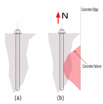
Figure D. (a) Bolt rest at concrete (b) bolt having concrete failure (Side-blow) near edge to tension force
Factored concrete side-face blowout strength of an anchor is defined in ACI 318-19 – 17.6.4 as
\( \phi N_{sb} = 160C_{a1}\sqrt{A_{brg}}\lambda _{a} \sqrt{f^{‘}_{c} } \rightarrow \) equation 17.6.4.1
where:
\( f^{‘}_{c} \) – specified compressive strength of concrete.
\( A_{brg} \) – net bearing area of the head of stud, anchor bolt or headed deformed bar.
\( \lambda_{a} \) – modification factor to reflect the reduced mechanical properties of lightweight concrete in certain concrete anchorage application.
Concrete pryout strength of anchor