
の プレートセクションのカット tool lets you extract forces, 瞬間, and other plate results across slabs, プレート, または壁. It works in two modes: 切る, which reads results along a single line, そして ストリップ, which integrates results over a defined width. これはスラブ ストリップの設計に役立ちます, ローカルプレートの動作をチェックする, 負荷分散の検証.
プレートセクションカットツールの使用方法
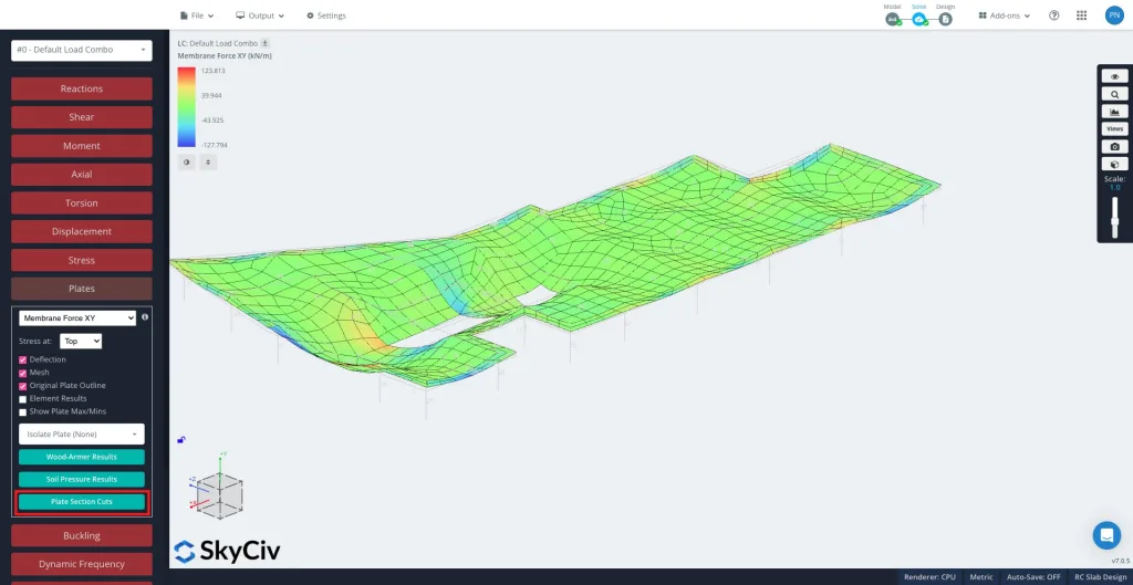
解決後, 選択する プレート その後 プレートセクションのカット 左側のパネルで.
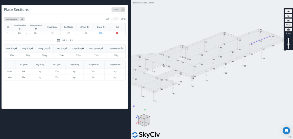
クリック 「新しいカットを追加」 新しいエントリを作成するには.
各カットの内容は、:
- ロードコンボ – 結果を抽出する荷重の組み合わせを選択します.
- コンポーネント – 結果のタイプを選択します. The available components depend on the active mode (Cut or Strip) – see the sections below.
- 開始ノード / エンドノード – カットが配置されるセグメントを定義します. You can also enter coordinates directly, 例えば.
[0,0,0]. - オフセット – Optionally shift the cut line. Enter it as
a,b, どこ a is the node ID that sets the offset direction and b is the offset distance (例えば.1, 0.5).- これは、座標を手動で計算せずに、エッジから設定されたオフセットでグラフを作成する場合に便利です。.
使用 切る / ストリップ toggle in the top right corner to switch between the two modes. They differ in what they extract and which components are available.
描画できるようになりました & ラン・ザ・カット
押す 走る カットを生成する. カットラインがモデルに表示されます (画像の右側に示すように), そしてその 結果表 選択した各コンポーネントの最大値と最小値が入力されます.
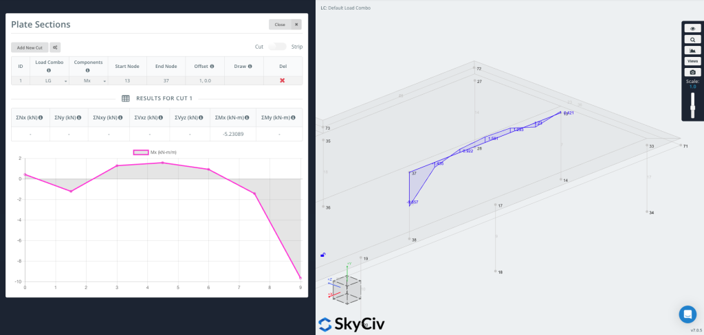
グラフをプロットできるようになりました ジオメトリに直接, カットラインに沿って結果値を視覚的に表示.
Cut Mode – Results Along a Line
に 切る mode the tool reads plate results along the cut line and reports them per unit length, together with the summed (Σ) total along the whole cut.
- コンポーネント – Nx, の, Nxy, Vxz, Vyz, Mx, ぼくの (または すべて at once), the Wood-Armer design moments (M1 / M2, 上 / 下), and Soil Pressure.
- 軸 – Results are reported in each plate’s local axes.
- 単位 – Force or moment per unit length for the diagram; the results table shows the totals ΣNx … ΣMy along the cut.
Strip Mode – Results Over a Width
Turn on the ストリップ toggle in the top right corner to generate a strip section.
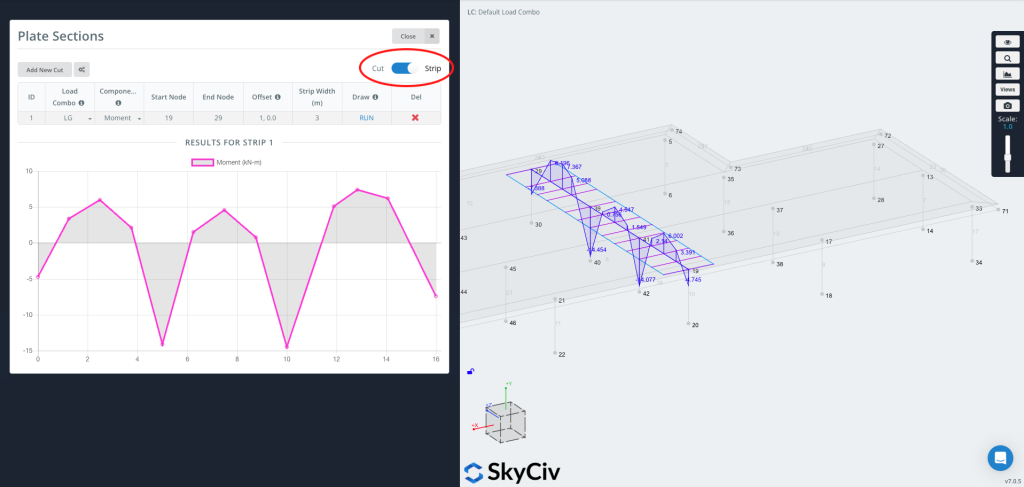
あ ストリップ 結果を抽出します 幅にわたって, not just along a line. At each station along the cut it integrates the plate results across the strip width, so the reported value is the total force or moment carried by that slice of slab. This is typically used for スラブストリップのデザイン, where design codes work with forces and moments over a strip of slab rather than at a single point.
Strip axis convention
A strip has a longitudinal axis running from the start node to the end node, and it is treated as an equivalent ビーム along that axis. All plate results are first transformed into this axis and then integrated across the strip width: the bending moment is reported about the strip axis, just as you would read the bending moment of a beam running along it, and the axial, shear and in-plane shear forces are resolved and summed the same way. 要するに, the distributed plate forces are reduced to the resultant forces and moments that an equivalent beam of that width would carry.
ストリップは必要なときに便利です:
- 一方向または双方向のスラブ ストリップの設計値
- 単一のラインではなく、物理的なストリップ上のより代表的な値
- Code-based averaging of peak values (see Peak Moment Ratio below)
Strip-specific inputs
- Strip Width – Enter
Wl,Wrfor an asymmetric strip, どこ Wl is the width to the left and Wr the width to the right (viewed from start to end). Enter a single value for a symmetric strip. - コンポーネント – Moment, 剪断, アキシャル, In-plane Shear, そして M comb top / M comb bot (combined reinforcement design moments – see below).
- Peak Moment Ratio (オプション) – Enable this option in the settings to cap the peaks of the diagram and distribute the moment more evenly across the strip, as required by code-based averaging such as the CSA two-thirds rule. Enter a ratio between 0 そして 1 (1.0 = no capping).
M comb top / M comb bot (combined design moments)
The “M comb” components are the combined Wood-Armer design moments. At every point a plate carries two bending moments and a twisting moment Mxy. Reinforcement bars resist bending along their own direction but not twist, so the twisting moment has to be folded into the bending moments – the Wood-Armer method does this, giving a single equivalent design moment for each reinforcement layer.
上 そして 底 refer to the two reinforcement layers (the two faces of the plate), and they are defined by the local z-axis of each finite element’s coordinate system: the face the local +z axis points toward is the 上, and the opposite face is the 底. Because the local axes are assigned per element – and depend on how each element is defined and the order of its nodes – check the element local axes in the model to confirm which physical face is top and which is bottom. M comb top sizes the reinforcement near the top face, そして M comb bot the reinforcement near the bottom face.
Because the results are integrated across the width, Strip values are reported in force or moment units (not per unit length).
Cut vs Strip – Which to Use
- 使用する 切る for a quick diagram of a result component along a line (in plate axes), or to get the total (Σ) across the cut.
- 使用する ストリップ when you need design forces and moments over a finite width (スラブストリップのデザイン), combined reinforcement moments (M comb), or code-based peak averaging.
