メンバー固定の意味と Structural 3D での識別方法
メンバー エンド フィクティは、メンバーが相互に、またはエンド ノードにどのように接続されるかを制御し、固定などの条件を含みます。, 固定, またはスプリング接続.
メンバーエンドの固定性コードは「F」を受け入れます’ (修繕), 'R’ (リリース済み) そして「S」’ (春) 値. このコードは、各メンバーのエンド ノードへのメンバー エンドの接続を参照します。 6 次の順序で自由度:
- ローカル x 軸の移動
- ローカル y 軸の移動
- ローカル Z 軸移動
- ローカル X 軸の回転
- ローカル y 軸回転
- ローカル Z 軸回転
注意: メンバー側の固定事項は、メンバーの ローカル軸システム グローバル軸システムではなく.
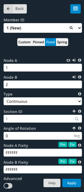
修繕 メンバーは完全に固定されています, 固定コード「FFFFFF」で指定された剛接続.
ピン留め メンバーにはコード「FFFFRR」で示されるヒンジ接続があります.
春 メンバーには半固定接続があり、コード「FFFFSS」で示される部分的な柔軟性が可能になります。.
カスタム値を指定するには, 確実に カスタム ボタンが選択されています. これにより、終点固定フィールドを編集できるようになります。.
モデル空間を見ながらメンバーの端の固定性を判断する方法
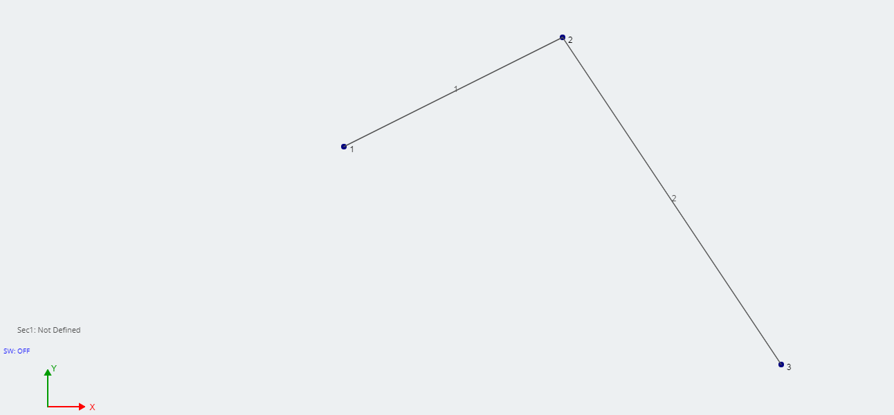
メンバーと一緒にモデルをするとき, メンバーを知るのに便利です’ 各メンバーを個別にクリックすることなく固定性を終了します. デフォルトでは, メンバーがモデル化されると、完全に固定された端部固定が行われます。 (FFFFFF). メンバーはノード間の 1 本の線のように見えます:

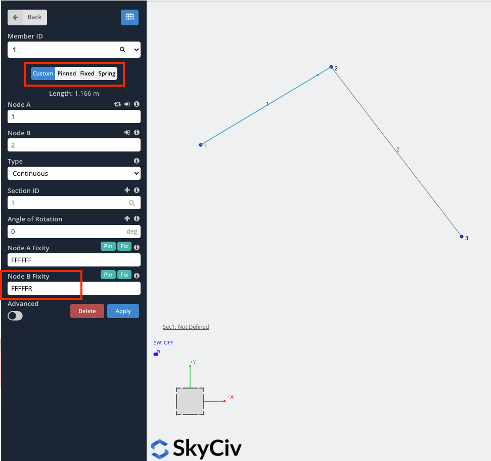
いずれかの自由度を解放したとき, メンバーの端近くに小さな点が表示されます (以下の赤丸で囲った部分のように). 例えば, ピン留めされた端部固定具を備えたメンバー用 (FFFRRR), メンバーはこんな感じになります:

詳しい説明
メンバーの固定情報の詳細については、, SkyCiv に技術記事があります (ビデオを含む) 私たちのブログで, に焦点を当てる メンバーの固定性をモデル化する方法:
例: ピン接続またはヒンジをモデル化する方法
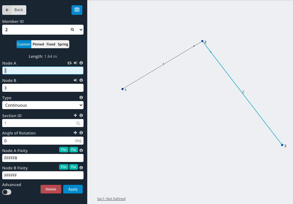
この例では, 単純なピン接続を作成します, ヒンジなどの. まずは作成から始めましょう 3 ノードとノードの結合 2 会員. この例のノードでは, 2 ヒンジになります.
詳しくは
詳細については, SkyCivにはさらに詳しい説明があります ヒンジをモデル化する方法, 構造解析ソフトを使って.
ビデオ: 自由度と固定性コードの説明