偏心荷重とは?
偏心荷重とは、次のような荷重です。 重心には適用されません メンバーの. 有限要素解析では, 点荷重, 分布荷重, 他の力は通常、断面の重心に適用されます。 (つまり. 断面の幾何学的中心). しかしながら, 特定のシナリオでは、中心から外れた力を加えたい場合があります – 例えば, I ビームのフランジに荷重を加える, ウェブというよりも. これを横荷重と仮定すると, これにより、ねじれ力が発生し、部材に全体的に異なる荷重挙動が発生します。.
モデルに偏心荷重を加える方法
ここでは、使用方法の例を紹介します リジッドリンク このような偏心荷重を加えると. リジッドリンクを使用する, 荷重を部材の重心から別の場所に転送できます. リジッドリンク この種の作業に非常に役立ちます, ある場所から別の場所への合力モーメントやその他の力を自動的に計算します。.
に向かいます S3D そして新しいモデルを作成します. 次, 右側のパネルでペンツールを選択するか、タップしてペンツールを選択します。 V . 1 回クリックして最初のノードを原点に配置します, その後、約2m上方に引き上げます (6.5フィート) 列を作成するには.
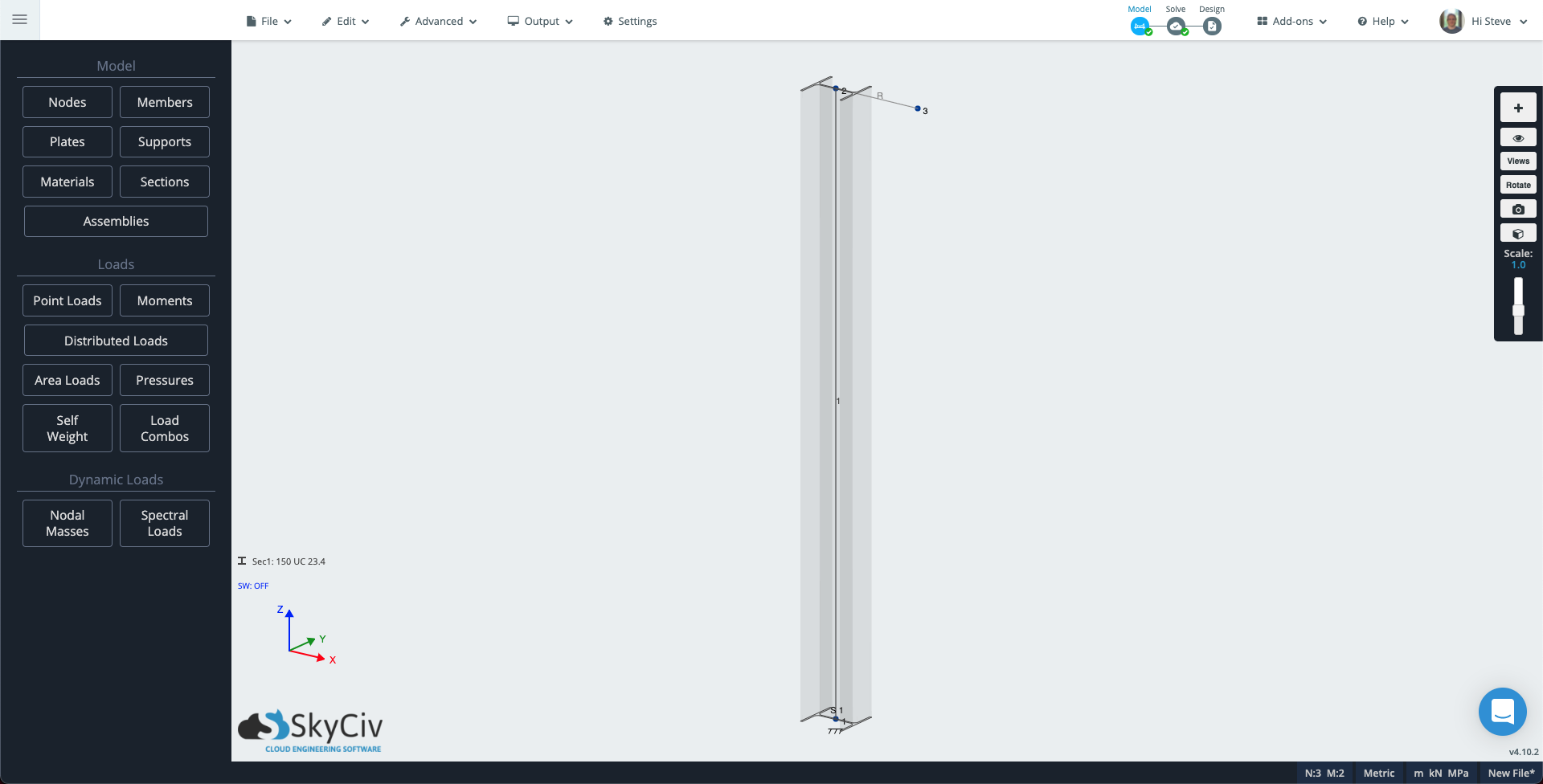
座標系では隅っこにある, クリック Sec1: 定義されていません, 次に、左側のパネルで, クリック ビルダー セクションビルダーを開く. 列セクションを選択してください, この技術ノートでは、オーストラリアの 150UC23.4 を選択しました。, これは約6です×6 私は帝国の友人のためにセクションを作成します. 左側のパネルで, サポートをクリックし、ノードに固定サポートを追加します 1.
次に、別のメンバーを追加して、ねじりを誘発する偏心荷重と柱に座屈効果を生み出す別の荷重を作成できるようにします。.
列の方向を確認するには, 右側のパネルの表示アイコンをクリックして、 3Dメンバー. ペンツールを使用して300mmを描画します。 (1フィート) 柱の上から X 方向のメンバー. もし “3Dメンバー” スイッチが入っています, このメンバーが列セクションを使用していることがわかります。. 新しいメンバーをクリックします, 次に、左側のパネルで, type 属性を次のように変更します 堅い をクリックします 適用する.
モデルは次のようになります。:
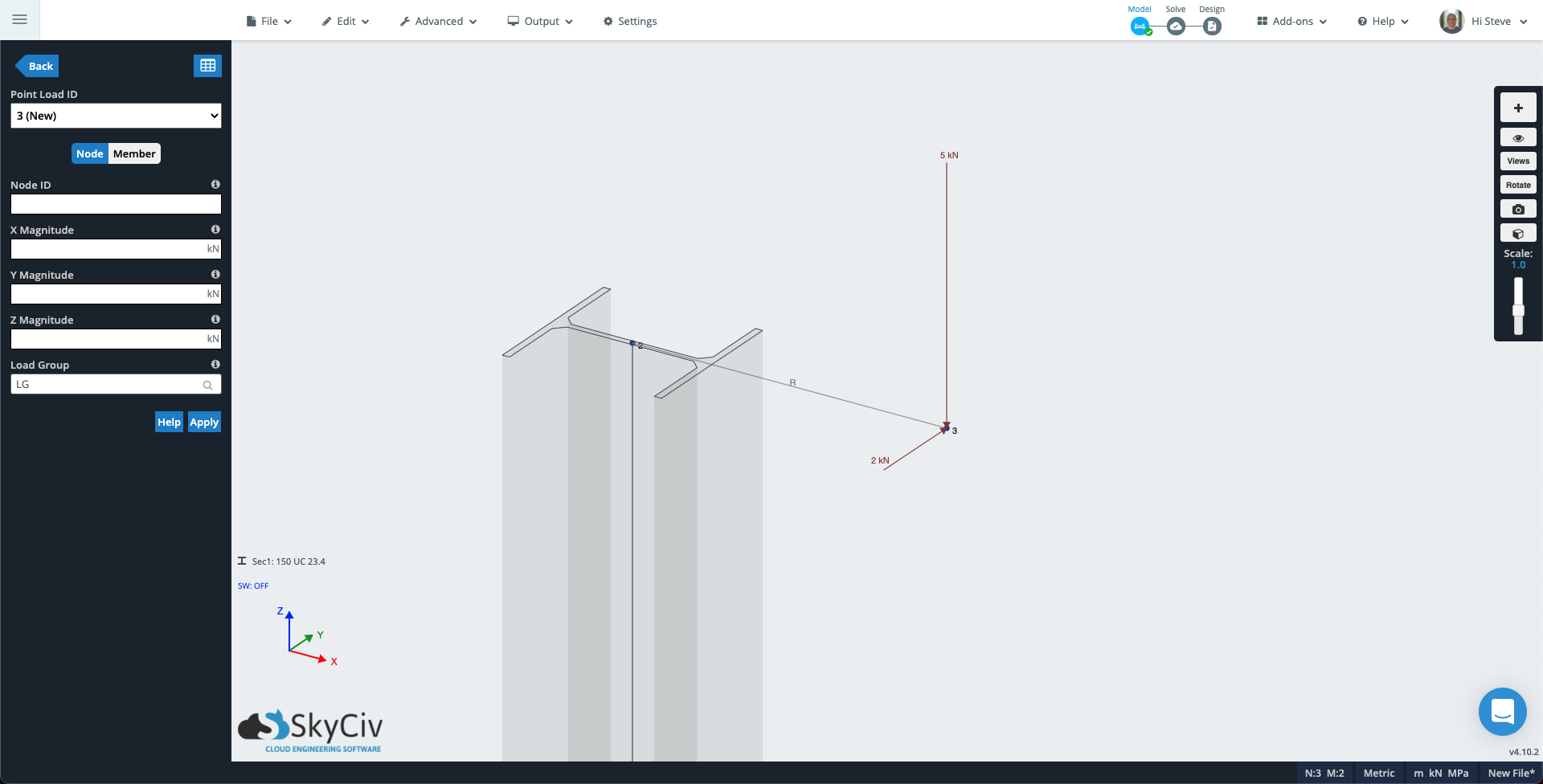
左側のパネルで [点荷重] をクリックします。. 属性に次の値を入力します:
- メンバーがいます: 3
- マグニチュードから: -5 (モデルが Y 軸を垂直として使用している場合, 代わりにこの値を Y の大きさに追加します).
- 負荷グループ: 座屈荷重
[適用]をクリックすると、点荷重がモデルに追加されます。. ポイント ロード ID は次のように増加します。 2 (新着) そこで別の荷重を加えて柱にねじれを生じさせます:
- メンバーがいます: 3
- そしてマグニチュード: 2 (モデルが Y 軸を垂直として使用している場合, 代わりにこの値を Z の大きさに追加します).
- 負荷グループ: ねじり荷重
ノード 3 モデルの内容は次のようになります。.
ソルバーを実行する, 次にレンダリングモードを開きます – 右側のパネルの立方体アイコン. 左側のパネルのドロップダウンを次のように変更します。 座屈荷重, たわみスケールを 自動, メンバー結果ドロップダウンは次のとおりです。 変位合計. 最初の偏心荷重がどのように座屈効果を引き起こしているかを確認できます。.
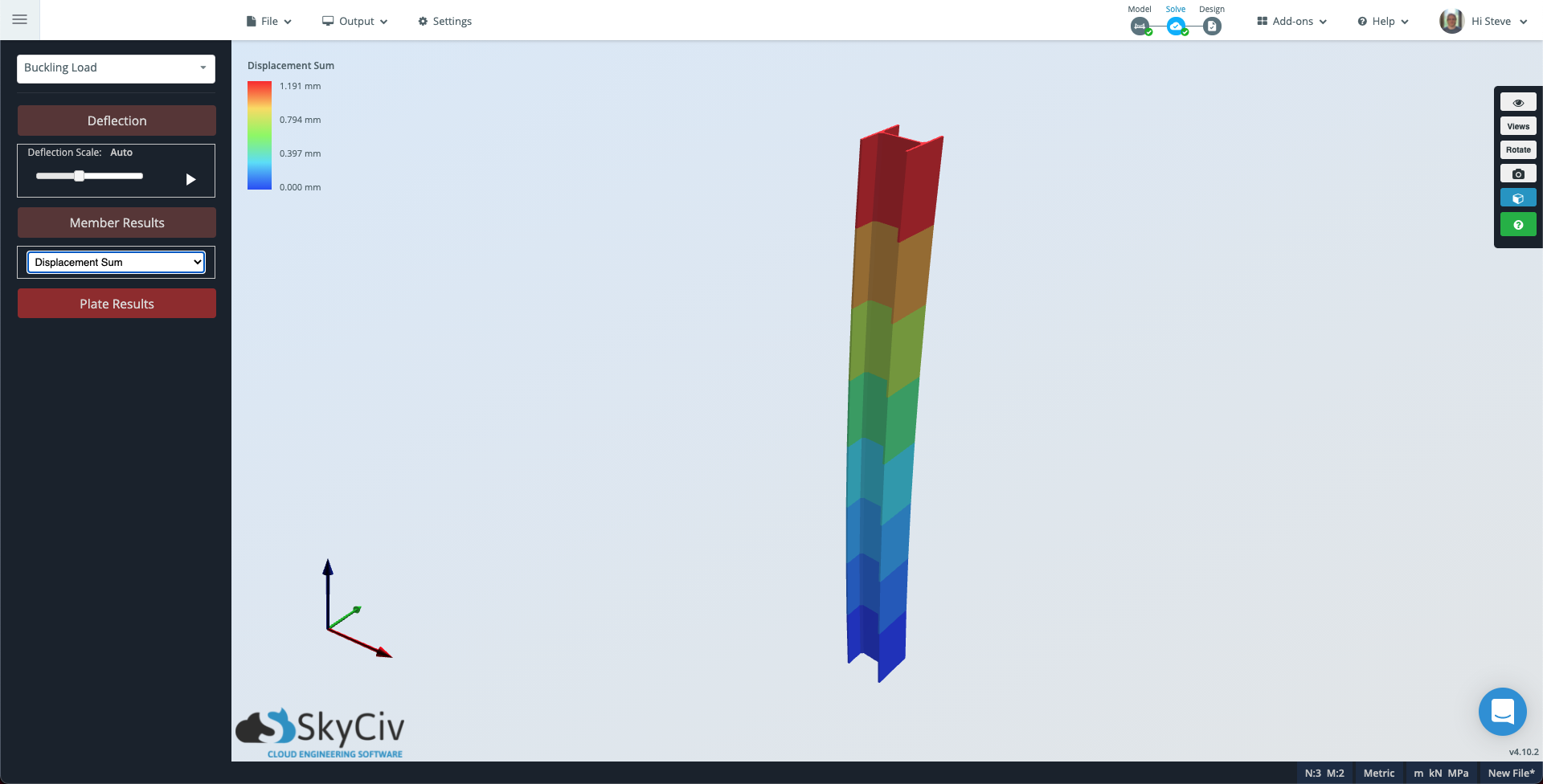
メンバーをさらに詳しく確認したい場合は、次のリンクにアクセスしてください。 設定 右から左に、選択ボックス内に完全に含まれている要素のみが選択されます ソルバー, 変更 メンバーごとの評価ポイント 適切な数値に変更して、再度解決を実行します.
次に、ドロップダウンをから変更します 座屈荷重 に ねじり荷重 そしてその メンバーの結果 に ねじり応力. この場合, ねじり荷重が部材全体で一貫しているため、部材は灰色で表示されます。.
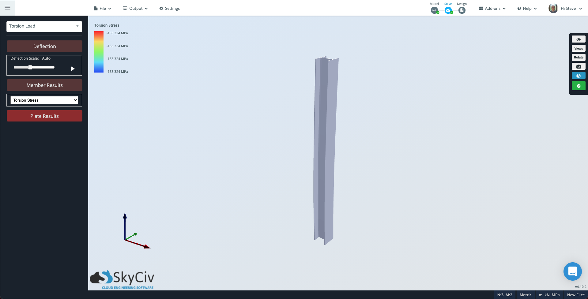
左上の等高線スケールは、柱が受けているねじれの大きさを示していることに注目してください。.