「R」をタップして、角度または相対位置によってメンバーをすばやく追加します’
従来のモデリング手法に加えて、 構造3D, SkyCiv の相対メンバー機能は、ユーザーに自分の構造をより迅速かつ簡単にモデル化する別の方法を提供します.
を使用するには、 相対メンバー 関数, まずノードを選択し、次のいずれかを選択します:
a) 「R」を押します, または
b) ノードを右クリックして選択します 相対メンバーを追加.
これにより、以下に示すように、モデル空間内を移動して表示を最適化できる小さなポップアップが表示されます。:
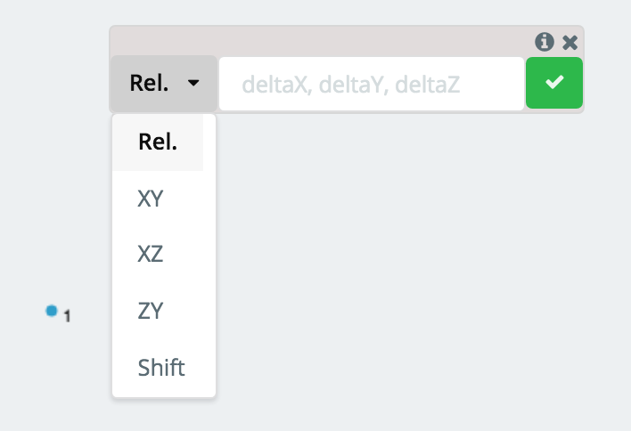
ここから, ドロップダウンを使用して、相対メンバーを追加する方法と、必要なデータを入力する入力フィールドを選択します. 主な方法は2つ (リリース, 長さ/角度) 相対メンバーの追加, これについては以下で説明します:
グローバル軸投影を使用した相対メンバーの追加
の “リリース” メソッドは、相対メンバーを追加するためのデフォルトのメソッドです. 入力フィールドに表示される 3 つの値 (デルタX, デルタ Y, デルタZ) 選択したノードから新しく生成されたノードへの位置の変化に対応します. これは、X の変化がわかっている場合、3D 空間でのモデリングに特に役立ちます。, そして, と端点の間の Z.
例:
選択したノードが, ノードと言う 1, の位置にあります (0,1,4) Nodeからメンバーを生成したいと考えていました 1 のノードに (10,12,8), ノードと言う 2, あなたは置くでしょう (10,11,4) の値として (デルタX, デルタ Y, デルタZ). 新しいノードへの投影は点線で表示されます。:
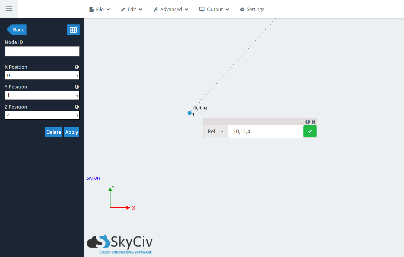
緑色のチェックマークをクリックします, または殴る 入る, メンバーの世代を受け入れる. 相対メンバー ウィンドウは表示されたままになるため、複数のメンバーを連続して連結できます。. 別のメンバーを生成することを選択した場合, 起点ノードは Node になります 2, デルタ値はそれに対する相対値になります, ノードではありません 1.
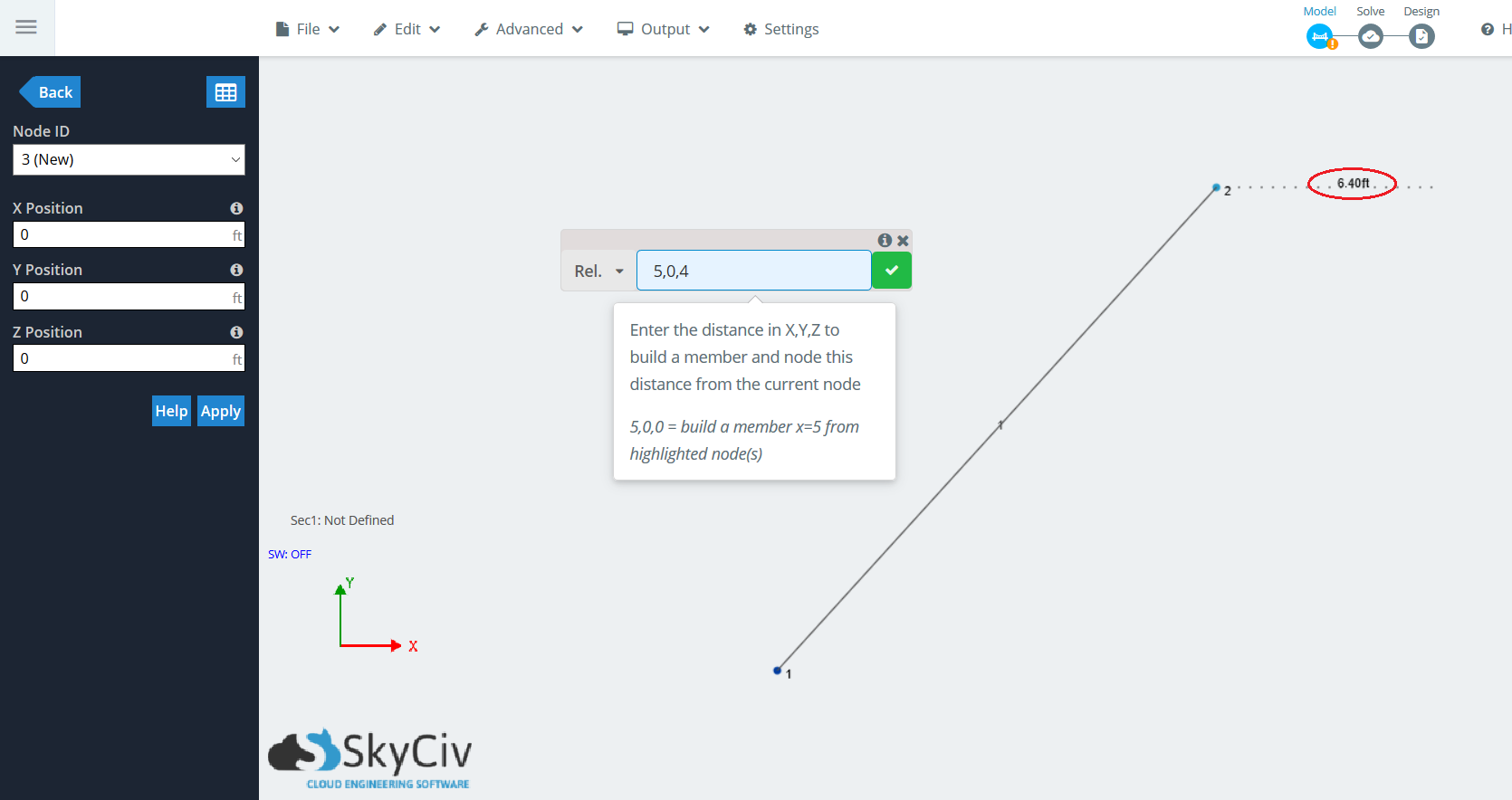
下の画像にある注意事項, 点線の投影線が表示されている間, メンバーの長さが表示されます, ペンツールを使用する場合と同様:
角度と長さを使用した相対メンバーの追加
この方法を使用すると、ユーザーは部材の長さと角度を素早く入力して、角度付き部材を作成できます。. 2D 空間でモデリングする場合に便利で、作成したい部材の角度と長さがわかっています。. 水平からの角度を入力することで、選択したノードからメンバーを作成できます (反時計回り) そしてメンバーの長さ.
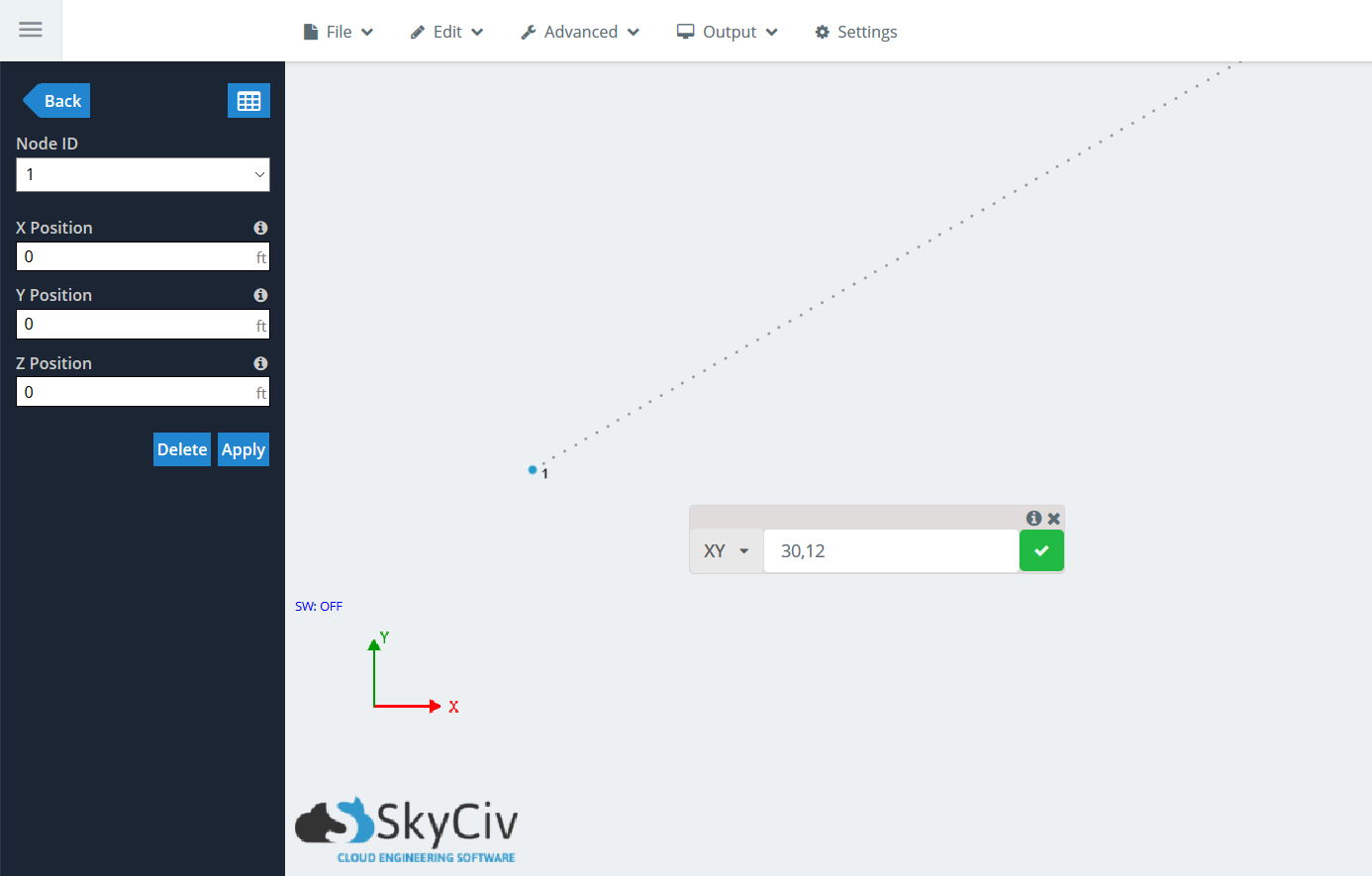
3D 空間でノードを生成するために使用できる平面は無数にあるため、, ユーザーは、3 つのグローバル軸平面のいずれかでこの方法を使用できます。: XY, YZ, とXZ. これら 3 つのオプションの入力フィールドに表示される 2 つの値 (角度, 長さ) 水平からの角度と部材の長さに対応します。, それぞれ.
例:
次のノードを起点として、XY 平面に角度の付いた部材を生成するとします。 (の,の,の), ノードと言う 1. メンバーが座っているのは知っています。 30 水平からの角度, この場合は X 軸, そして 12 フィート長さ. ノードを選択してください, 「R」を押してください’ を持ち出すために 相対メンバー 関数. ドロップダウンをクリックして、次の場所に移動します。 “XY”. 入れて (30,12) 入力欄に, 投影は再び点線で表示されます:
緑色のチェックマークをクリックします, または殴る 入る, メンバーの世代を受け入れる. 相対メンバー ウィンドウは表示されたままになるため、複数のメンバーを連続して連結できます。. 別のメンバーを生成することを選択した場合, 起点ノードは Node になります 2, デルタ値はそれに対する相対値になります, ノードではありません 1.
複数の相対メンバーを同時に追加する
同じ 相対メンバー メンバー関数は単一のメンバーを生成するために使用できるだけではありません, ただし同時に複数. ワークフローは同じです, ただし、ユーザーは相対メンバーを生成する複数のノードを選択できます。. これらのノードは同じ平面上にある必要はなく、プロジェクト内のどこにでも配置できます。.
例:
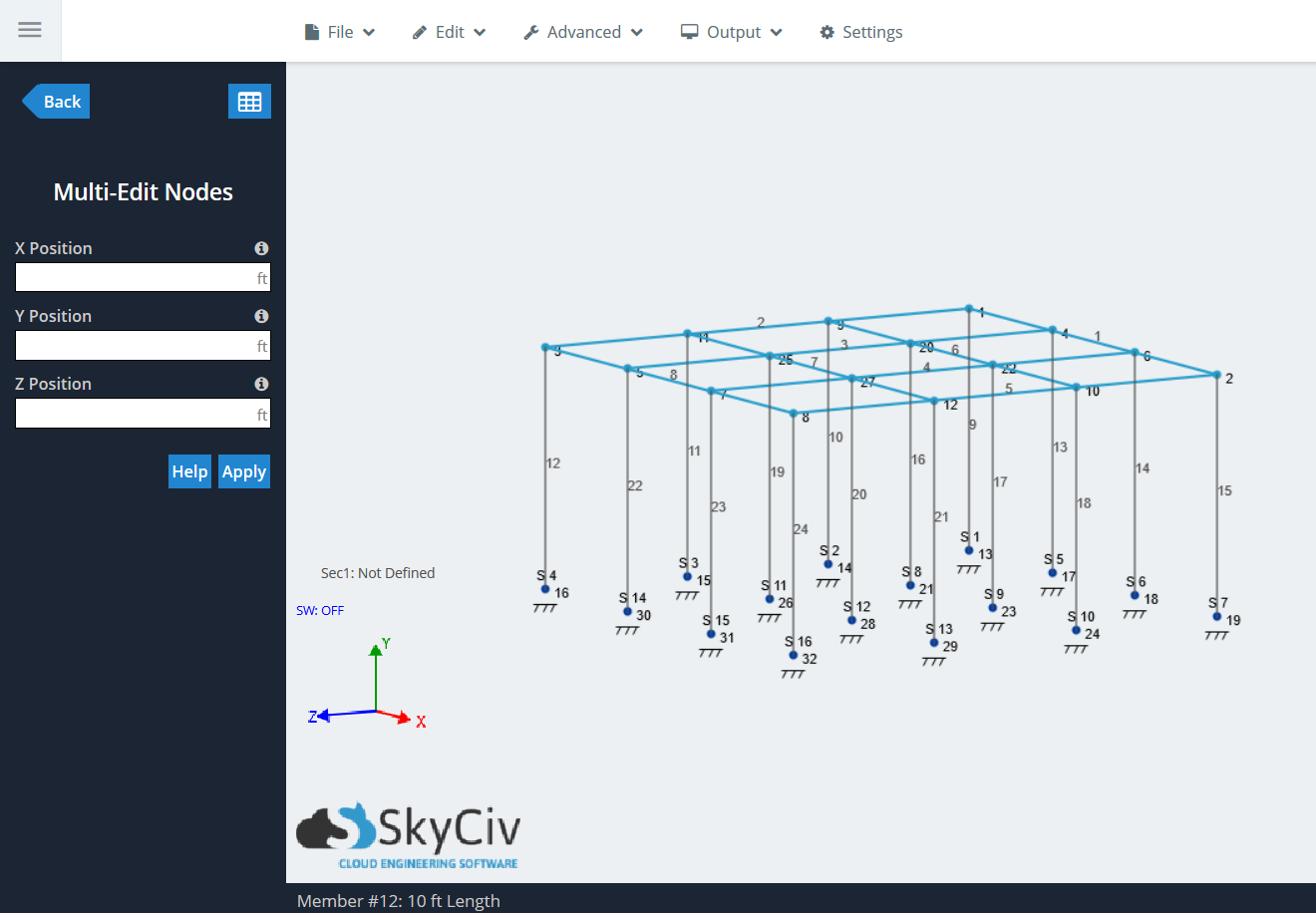
この例では, 次を使用して非常に簡単に生成できる、単純な高架プラットフォームを見てみましょう。 アセンブリテンプレート 構造3D内. まず、Ctrl をクリックし、右から左にドラッグして一番上のものを選択します。 “床” ノードとメンバーの.
注意: の 相対メンバー 関数はノードからのみメンバーを生成します, メンバーからではなく.
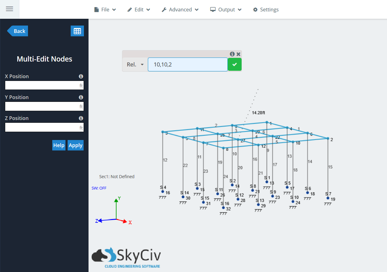
今, を使用して相対メンバーを作成します。 “リリース” 関数. 押す “R” を持ち出すために 相対メンバー 関数と入力 (10,10,2) デルタ値について. 部材の長さに加えて部材線を示す投影線があることがわかります。:
緑色のチェックマークをクリックしてメンバーを生成します. プロセス中に選択されたすべてのノードに対して作成されたメンバーとノードが表示されるはずです。.
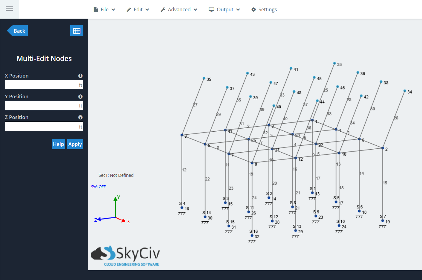
複数の相対メンバーを同時に追加できるため、ユーザーはほぼ無制限のモデリングの可能性への扉が開きます。. 次にプロジェクトをモデリングしているときに試してください.
相対メンバー関数使用時のシフト
Relative Member 関数内にある最後の便利な機能は次のとおりです。 “シフト”, これはドロップダウン メニューの最後の項目です. これは、同じシフト ノード機能を使用するための迅速かつ簡単なショートカットです。, にあります 編集する > 操作 > シフトノード. 単一または複数のノードを 3D 空間内で移動させることができます, そしてメンバーとのつながりを保ちます. に似ています “リリース” 関数, ユーザーは各グローバル軸の投影距離を入力する必要があります。.
例:
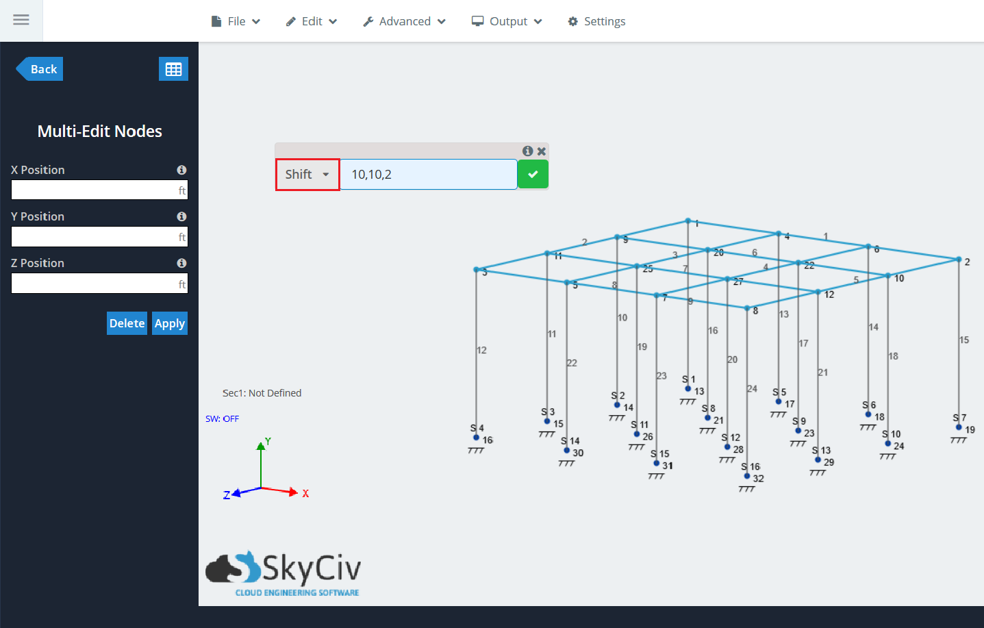
最後の例で同じ高架プラットフォームを使用する, で同じ要素の選択を繰り返します。 “最上階” プラットフォームの. 押す “R” 見つけて “シフト” ドロップダウンで. 前と同じ値を入力します: (10,10,2). シフト機能使用時, 新しいメンバーが生成されていないため、投影線は表示されません。:
緑色のチェックマークをクリックします. 以前に選択したすべてのノードが、指定された場所に移動します。, メンバーも移動する:
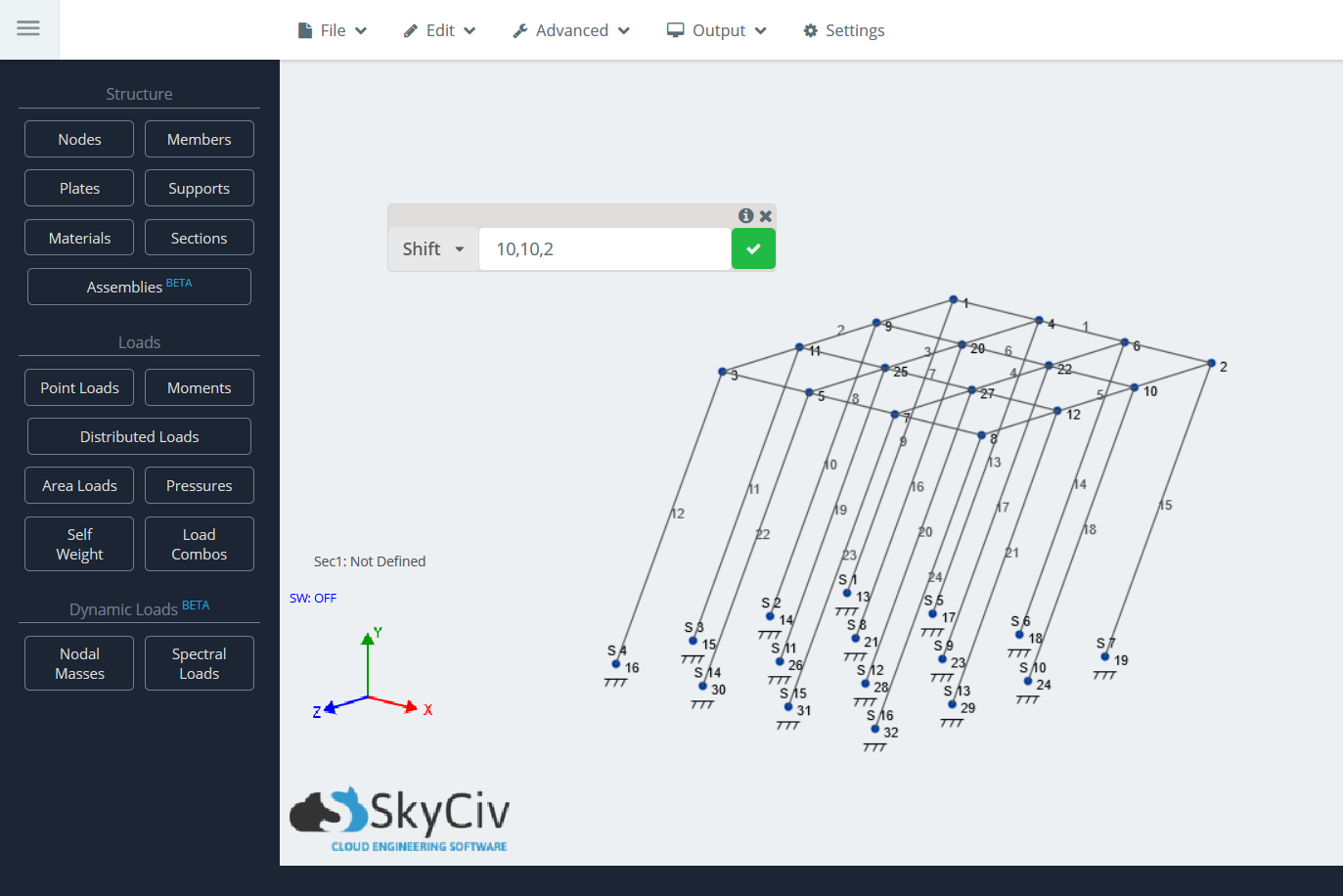
注意: これは単一ノードでも実行できます.