
A column splice joins one column to the one above it. Columns arrive in mill lengths, and a building taller than that length needs its columns spliced, usually a few feet above floor level where the erector can reach the joint from the deck. Splices also turn up in retrofit work, where a column is extended, replaced or reinforced after a change in loading.
The splice has to carry whatever the column carries across the joint: 軸圧縮, axial tension where uplift or overturning governs, 剪断, と瞬間. AISC 360-16 sets out the procedures for each. This page walks through designing one in SkyCiv Connection Design.
柱スプライス接続の背後にある計算
A column splice is a slow connection to calculate by hand. Each plate has to be checked in tension, compression and bearing, each bolt group in shear, and the whole joint for block shear, all of it doubled because the upper and lower columns are separate connections either side of the splice. AISC 360-16 gives the procedure for the axial, shear and moment capacity of each of those pieces.
の column splice calculator runs the same procedure. You supply the column sections, プレートサイズ, bolt specifications and loads, and it returns every check with its utilization ratio and the clause it came from, so the arithmetic stops being the part of the job that takes the time.
ボルト締めまたは溶接: 適切な接続方法の選択
Bolting is the usual choice for a column splice. A bolted splice is made in the air by an erector with a wrench, it tolerates the small misalignments that come with erecting a frame, and it can be slackened and adjusted if something does not line up. Welding a splice at height means preheat, position welding and inspection on a joint that is hard to reach.
カラム接触面の準備: の “クマにフィット” アプローチ
Where the column ends are prepared so the two sections sit in full contact, compression transfers through bearing rather than through the bolts. That usually means fewer bolts and thinner plates, because the plates only have to carry tension, せん断と瞬間.
It is a decision that has to reach the fabricator. Fit to bear is a preparation requirement on the shop drawings, not something the connection design can assume on its own, so if you design on that basis, say so on the drawing.
柱スプライス接続の必要性
Splices appear wherever a column cannot be a single piece: buildings taller than the available mill length, sections that would be impossible to ship or lift in one, and retrofits where a column is extended or strengthened. In each case the splice has to reproduce the continuity the column would have had without it.
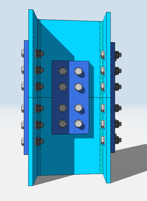
Designing a Column Splice in SkyCiv
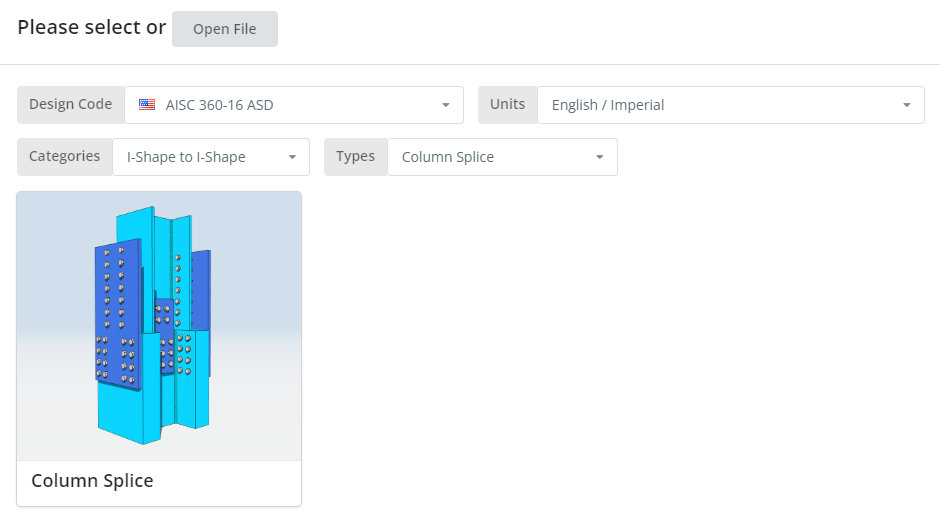
設計コードはAISCにすることができます 360-16 ASDまたはLRFD, 単位は英国/帝国またはSI/メートル法. クリック “柱のスプライス” タイル.
[詳細]タブ
![SkyCiv 接続設計の [詳細] タブ](https://skyciv.com/wp-content/uploads/2022/12/skyciv-project-tab-connection-design.png)
プロジェクトの詳細をここに記録します. どれも計算を変えるものではありません, しかし、それはレポートに反映されます, which is what makes a set of designs traceable later.
アセンブリ タブ
アセンブリの下に 3 つのタブがあります: the Lower Column, the Upper Column, そして接続, which holds the flange plate and web plate.
下の列タブ
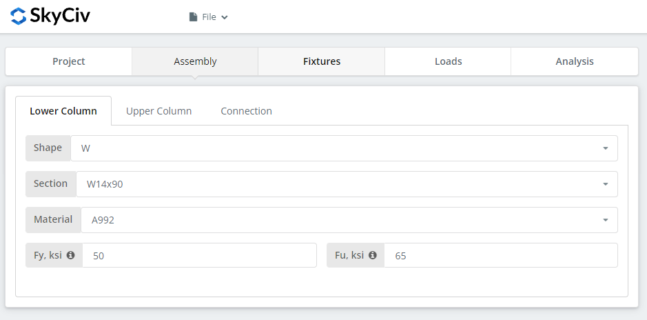
Specify the section and material grade of the lower column. A992 と A36 がリストにあります; それ以外の場合は、[カスタム] を選択し、Fy と Fu を入力します。.
上部列タブ
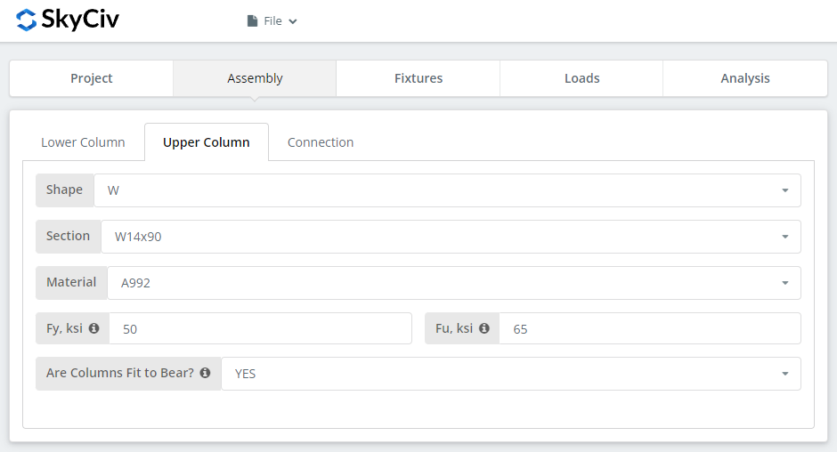
The same inputs, plus the option to declare the columns fit to bear. 選択する “はい” and the compressive load is designed at the column contact surface instead of through the bolted connection, which gives a more economical connection. 上記のように, that is a requirement you have to pass to the fabricator: the columns must actually be prepared to bear.
接続タブ: フランジプレート
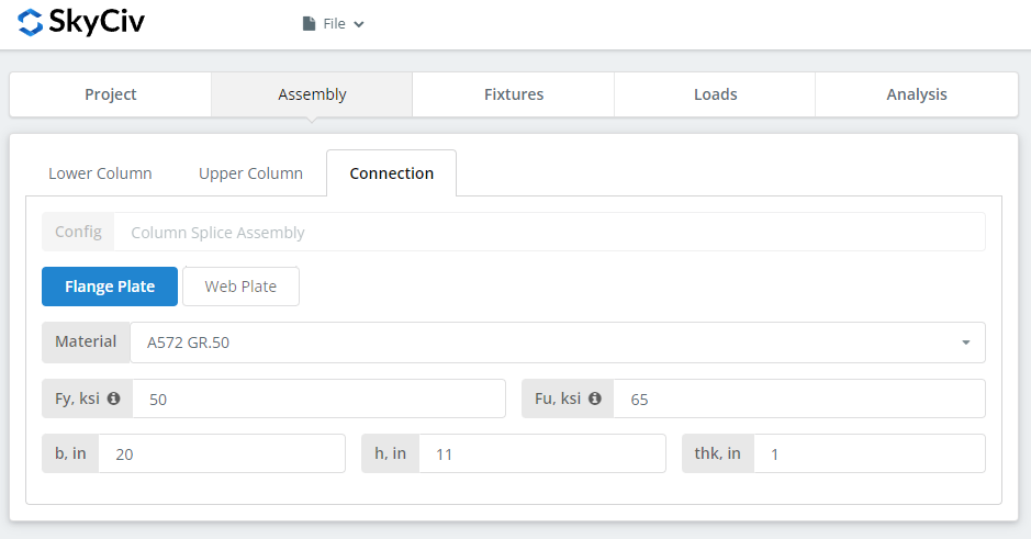
フランジ プレートのプロパティを設定する: グレードA36, A992 または A572 Gr.50, または独自の Fy と Fu でカスタム, それからb (幅), h (高さ) そして、そうだね (厚さ). Watch the 3D renderer as you type and check the plate geometry makes sense, in particular that there is room for the bolt group you are about to define on the Fixtures tab.
接続タブ: ウェブプレート
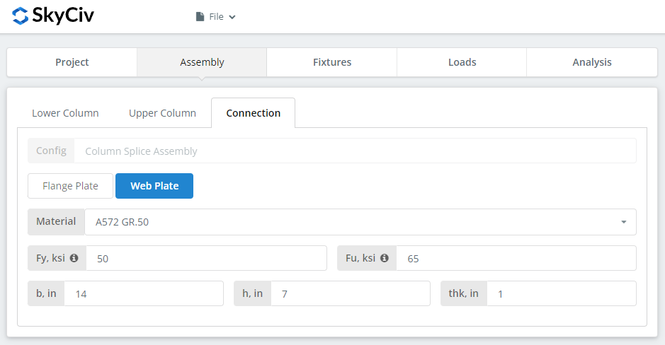
Same inputs as the flange plate. 次に進む前にレンダラーをもう一度確認してください.
備品 1-4 タブ
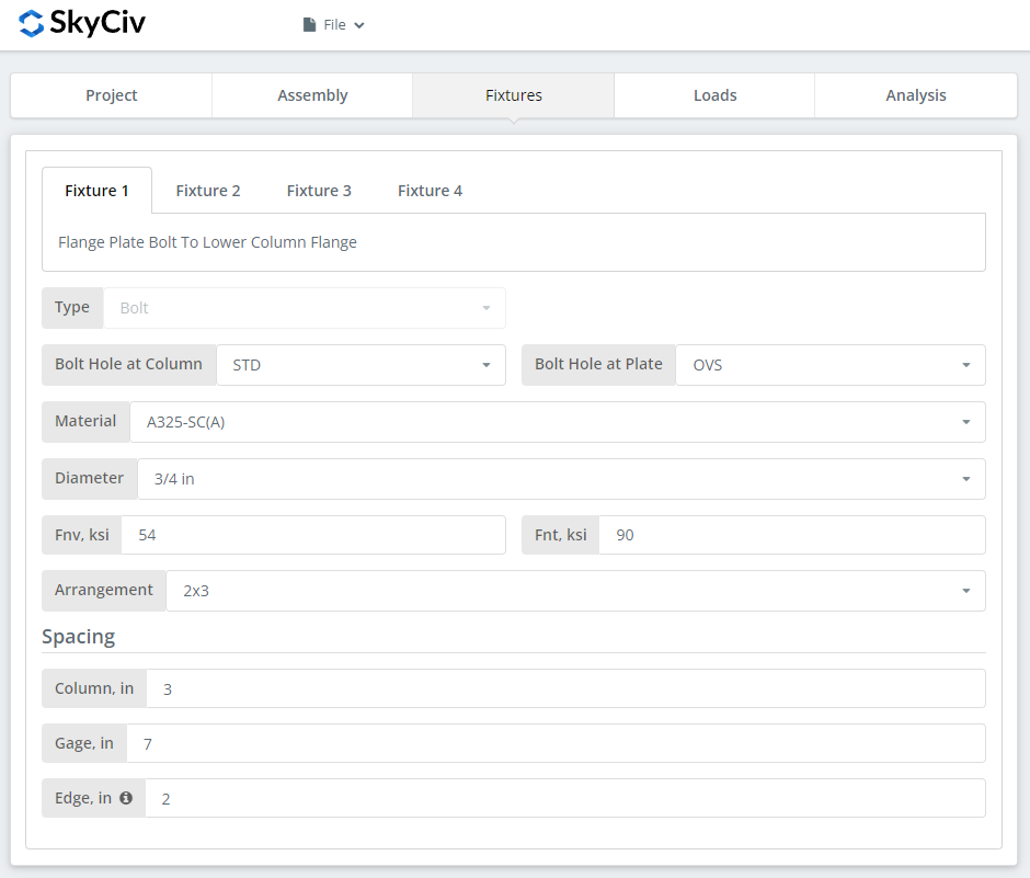
This is where the bolts are defined, one fixture per interface:
備品 1 – フランジプレートからコラム下部フランジまで
備品 2 – フランジプレートからアッパーコラムフランジまで
備品 3 – ウェブプレートから下部コラムウェブまで
備品 4 – ウェブプレートから上部コラムウェブまで
最初, the bolt-hole types at the column flange or web and at the plates. 製造業者は通常、標準の穴を要求します (STD) メンバーと特大の穴に (OVS) 皿の中の, 現場でのフィッティング公差を購入します.
次, ボルトの材質またはグレード: A307, A325, A490またはカスタム. A325 および A490 は ASTM F3125 内のグレードです。, 古いスタンドアロン仕様を統合しました, so a drawing calling for A325 is calling for F3125 Grade A325. ベアリングタイプ接続の場合は N または X、スリップクリティカル接続の場合は SC を選択してください.
スリップクリティカルジョイントは、ベアリングタイプよりも設計ボルト容量が低い, 実際に滑りが重要な場合に使用してください: 特大または長穴, 負荷反転, または疲労. この例では, using OVS holes in either the column or the plate means the bolts are automatically checked as slip-critical. NとXの間, X を指定すると、ボルトのせん断耐力が大きくなります, ただし、ねじ山はせん断面から除外する必要があります, which the erector has to know about. SC間(あ) とSC(B), これは、提案された根太の最大深さが、選択した根太のスパンと荷重の場合に対して小さすぎる場合に発生します。(B) より大きな容量が得られ、より徹底的に準備された接合面が必要です, 例: SSPC-SP6 業務用ブラスト洗浄.
続いてボルト径, 5/8より″ 1-1/2まで″ または同等のメートル法, そしてアレンジメント, まで 8 ボルト列と 12 ボルト柱. Set the bolt row spacing, 列間隔とゲージ. の “縁” input is the distance from the column end to the first bolt column.
For more on the fastener side of this, のドキュメントを参照してください ボルト.
「荷重」タブ
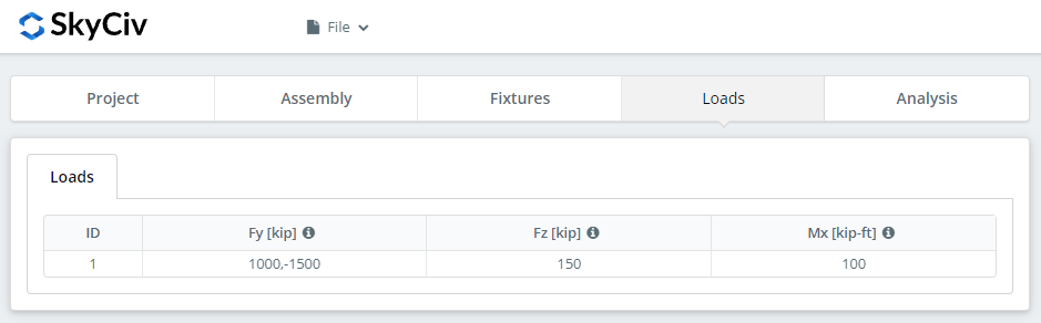
Enter the compressive or tensile load as ‘Fy’, the horizontal shear as ‘Fz’, and the strong axis moment as ‘Mx’. ツールチップにカーソルを合わせると、記号規則と各記号の方向が表示されます.
最初に選択した設計方法に荷重を一致させます. LRFD は設計強度に対して係数加重を考慮します; ASD は許容強度に対して使用荷重を受けます. ソフトウェアはあなたがどれを入力したかを認識できません, so mixing them produces a utilization ratio that means nothing.
[結果]タブ
![SkyCiv 接続設計の [結果] タブ](https://skyciv.com/wp-content/uploads/2022/12/analysis1-tab-skyciv-connection-design.png)
クリック “デザインチェックを実行する”. 以前のタブにないものは、黙ってデフォルト設定されるのではなく、ここでフラグが立てられます。.
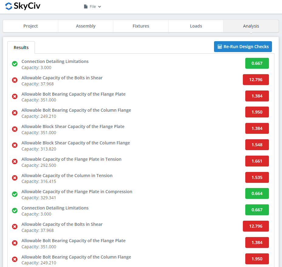
概要には、接続が成功したかどうかが表示されます, with a utilization ratio against each check and the governing one called out. 失敗した場合, 前のタブの入力を変更して、 “設計チェックを再実行する”. それが過ぎたとき, “計算レポートの表示” 詳細レポートを開きます.
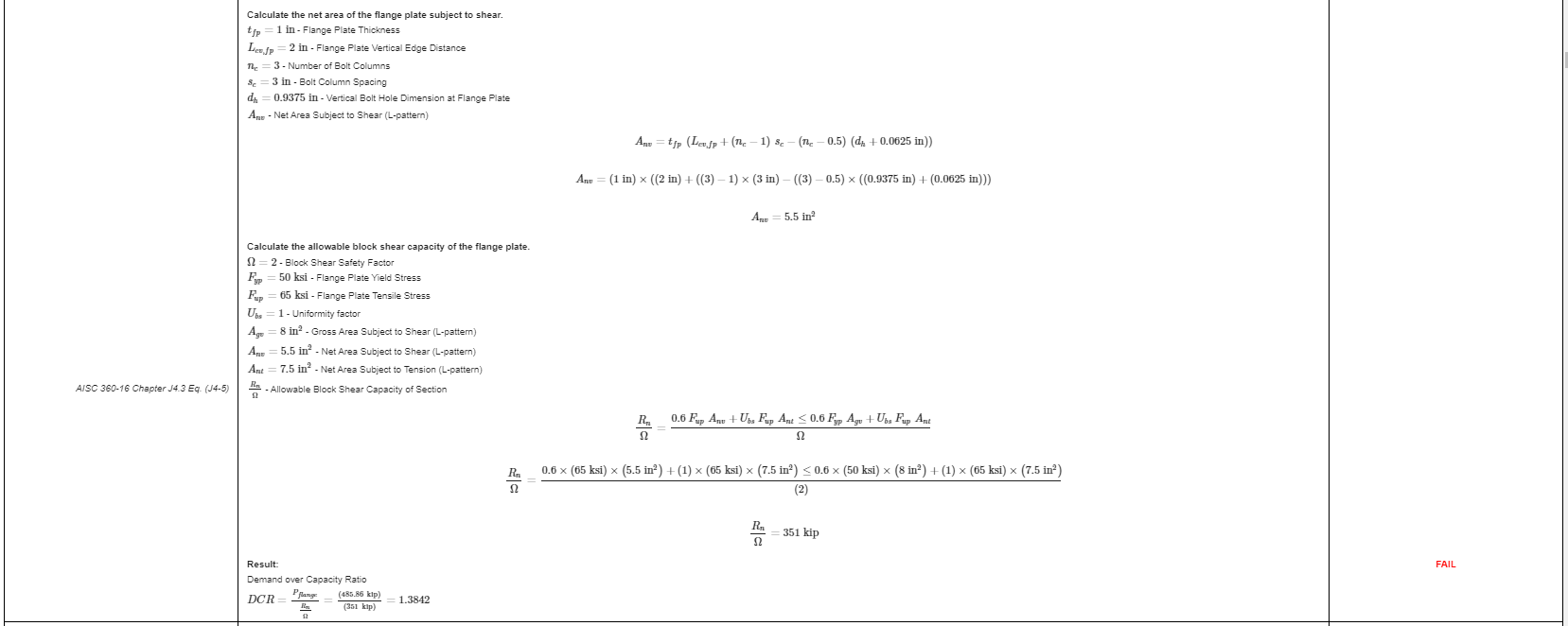
それはレポートからの抜粋です. 各チェックには、AISC マニュアルまたは仕様への参照が含まれています。, and the working is laid out the way the specification lays it out, so a reviewing engineer can follow it line by line instead of reverse-engineering a result.
ここに詳細な計算レポート全体の PDF コピー.
Designing a beam splice instead? の beam splice calculator works the same way.
自分で試してみる
The link below opens the module with the column splice already loaded. Enter your sections, プレート, ボルトと負荷, and every check and code reference is shown in full. ブラウザ上で動作します, インストールするものが何もない状態で.
