
モーメント接続とは?
モーメント接続は伝達するジョイントです 曲げモーメント 柱と梁の間, または任意の 2 人のメンバー間で. 梁の端部に内部モーメントがある場合, 接続は、端を自由に回転させるのではなく、ジョイント全体でそのモーメントを伝達する必要があります。.
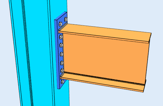
拡張エンドプレート接続, モーメントコネクションの一例. テンション フランジの外側のボルトにより、レバー アームが長くなります。.
の目的 瞬間接続 最後の回転を保持することです, 分析用語で言えば、 固定コード FFFFFF: 3 つの平行移動と 3 つの回転すべてで拘束される. そのため、モーメント接続は剛接続とも呼ばれます。.
AISC 360-16 これについてはセクション B3.4 がより正確です, フレームをモデル化する際には区別が重要です. 瞬間接続は次のいずれかです 完全に拘束された (NS), これはメンバー間の角度を保持し、FFFFFF の仮定を正当化します。, または 部分的に拘束された (PR), モーメントを伝達しますが、解析では関節の実際の剛性を考慮する必要があるほど十分に回転します. PR ジョイントを完全に硬いものとして扱うと、フレームの剛性が誇張され、ドリフトが過小評価されます。.
ここで、 せん断接続 主にビームウェブを通じて動作します, モーメント接続はフランジに係合する必要があります, そこに曲げ応力がかかるからです. フランジプレート, 溶接されたフランジまたはエンドプレートはすべて同じ役割を果たします: ビームのモーメントを一方のフランジでは引張力に、もう一方のフランジでは圧縮力に変換します。, そしてそのカップルを列に運びます.
モーメント接続タイプ
モーメント接続はせん断接続よりもはるかに大きなモーメントを伝達します。, そして作るのにもっとコストがかかる: より多くの材料, さらに溶接, より多くの調整とより多くの検査. ほとんどのフレームは、構造が横方向の安定性のためにフレームの動作に依存する場合にのみそれらを使用します。, 他の場所でもせん断接続を使用します.
どの構成が利用できるかは、設計コードとビームが何にフレームされるかによって異なります。.
梁から I 断面柱まで (AISC 360-16)
4つの構成, 柱フランジまたは柱ウェブへの枠組.
フランジプレート
プレートは梁の上部フランジと下部フランジを横切って走ります, 梁と柱にボルトまたは溶接で固定される. ビームが曲がると, 一方のプレートは張力がかかり、もう一方のプレートは圧縮状態になります, そしてそのカップルはその瞬間を運ぶ. ビームウェブは通常、別個のせん断プレートによって支えられます。, そのため、接続によりジョブが分割されます: フランジは瞬間を捉えます, ウェブが剪断力を発揮する.
を参照してください フランジプレート接続計算機.
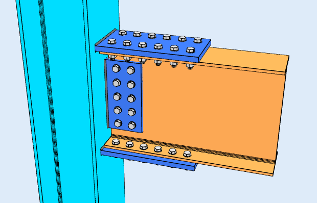
溶接フランジ
梁フランジは柱フランジに真っすぐに溶接されています, 中板なし, ウェブはせん断タブにボルトで固定されています. これにより、グループ内で最も剛性の高いジョイントと最もクリーンな荷重パスが得られます。, ただし、公差内に収める必要がある部材の現場溶接です。, それで予熱が行われます, ボルトで固定された詳細には存在しないアクセスと検査のコスト.
フラッシュエンドプレート
梁の端に溶接され、柱にボルトで固定されたプレート, プレートはビームフランジと面一に仕上げられ、すべてのボルトはそれらの間にあります. 低い瞬間に適しています, ボルトグループのレバーアームはビームの深さによって制限されるため.
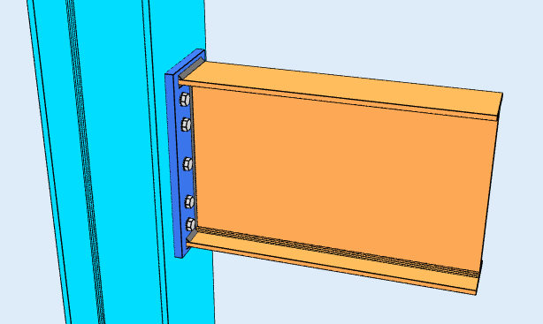
拡張エンドプレート
同じ考え, プレートがテンション フランジを超えて延長され、ボルトがその外側に収まるようにします. これらの外側のボルトには、圧縮フランジの周囲に長いレバー アームがあります。, これが追加のモーメント容量を購入するものです. 拡張部分でのこじ開け行為は統治チェックとなる. このページの上部に表示されている構成です.
両方のエンド プレート構成がカバーされます。 モーメント接続計算機.
ビームから HSS カラムへ (AISC 360-16)
モーメント接続を中空セクションに組み立てるのは困難です, ボルトを通すフランジがなく、反対側にアクセスできないため. 1 つの構成が利用可能です: a フランジプレート HSS の端面に溶接されています, 補強材なし.
なので 4100:2020
なので 4100 SkyCiv 接続設計の対象範囲はせん断接続のみです, 梁と I 断面柱、または梁と梁のフレーム構成. AS へのモーメント接続 4100 利用できません. 瞬間デザイン, AISCを使用する 360-16.
ソフトウェアは何をチェックしますか?
最初にディテールを実行します: ボルトエッジの距離, ボルトの間隔 (ピッチとゲージ), 工具のクリアランス, プレートの最小寸法と最大寸法, プレート間の衝突検出, 補強材, ボルトと溶接. 構築できない接続は解決に至りません.
その後、強度チェックがジョイントを通してカップルを追跡します. フランジ側では、プレートが張力と圧縮状態にあることを意味します, ボルトシャー, ボルトベアリングとティアアウト, ブロックせん断破壊, ボルトをこじる動作, 溶接スロートストレス. 支持部材では、局所的なフランジの曲げを意味します, Web ローカルの譲歩と Web の機能不全, 柱に補強材またはダブラー プレートが必要かどうかを決定する限界状態は次のとおりです。.
あらゆる式, デザインチェックとコードリファレンスが完全に表示されます, AISC の条項番号付き 360-16, そうすれば、信頼するのではなく、計算に従うことができます.
モーメント接続とせん断接続: 違い
違いは、2 人のメンバー間の角度に何が起こるかです. 瞬間接続でその角度を保持, したがって、一方の部材を曲げると、もう一方の部材にも影響が及びます. せん断接続では、ジョイントは自由に回転します, そのため、ビームの端が回転し、ジョイントを通過する意味のある瞬間はありません。.
| モーメント接続 | せん断接続 | |
|---|---|---|
| 移転した力 | せん断とモーメント | せん断のみ |
| 別名 | 堅い, 修繕, モーメント耐性 | ピン留め, ヒンジ, シンプルな |
| AISC 360-16 学期 | FRまたはPR瞬間接続 | 簡単接続 |
| 回転 | 回転を抑制します | 自由に回転可能 |
| ソフトウェア修正コード | FFFFFF | FFFFFR |
SkyCiv接続設計ソフトウェア
上記のモデルとチェックは、 SkyCiv接続設計. それはカバーします 80+ 事前設定された接続タイプ, にデザインする AISC 360-16 LRFDとASD、そして なので 4100:2020, すべての式を示します, デザインチェックとコードリファレンスの完全版.
接続を 3D でモデル化できます, ボルトを交換する, 荷重データを失うことなく溶接またはプレートを作成できます, CloudCAD で 2D 詳細図面シートを作成する, Revit で調整するために 3D ジオメトリを IFC にエクスポートします, Tekla または Navisworks.
完全にブラウザ内で動作します, ダウンロードなし, アップデートまたは IT セットアップ.
