記事上で, SkyCiv ソフトウェアを使用して鉄筋コンクリート梁を設計する方法を説明します。. このチュートリアルでは、ビーム設計のために SkyCiv が提供する 2 つのソフトウェア オプションについて説明します。: SkyCiv ビームと構造 3D. 梁に効果的にアクセスして設計できるよう、両方のツールについて詳しく説明します。. 記事の最後に, RC 梁の設計には ACI-318-19 で規定された係数の方法も適用します。.
ビーム設計が初めての場合, SkyCiv の入門記事を読むことをお勧めします。:
これらのチュートリアルは、梁を設計する一般的なプロセスをより深く理解するのに役立ちます。.
あなたがSkyCivで初めての場合, サインアップして自分でソフトウェアをテストする!
SkyCiv Beamソフトウェア
最初に行うのは、SkyCiv Beam ソフトウェアでビーム モデルを作成することです。. 表示します 必要な手順: (括弧内, データ例を示します):
- ダッシュボードページで, ビームモジュールを選択してください.
- 長さを定義する梁を作成する (66 フィート).
- サポートに移動し、ヒンジまたは単純なロッドを定義します (初めと終わりのヒンジ; 3 番目のポイントのロッド).
- セクションに移動して長方形を作成します (長方形断面; 幅=18インチ; 高さ=24インチ).
- 次に、分散負荷ボタンを選択し、1 つを割り当てます。, 二, 必要に応じて以上 (重畳死荷重 = 0.25 キップ/フィート; 活荷重 = 0.40 キップ/フィート)
- 次のステップでは、いくつかの荷重の組み合わせを作成します。 (\({L_d = 1.2times D + 1.6\L倍}\))
- 最後に, ビームを解く!
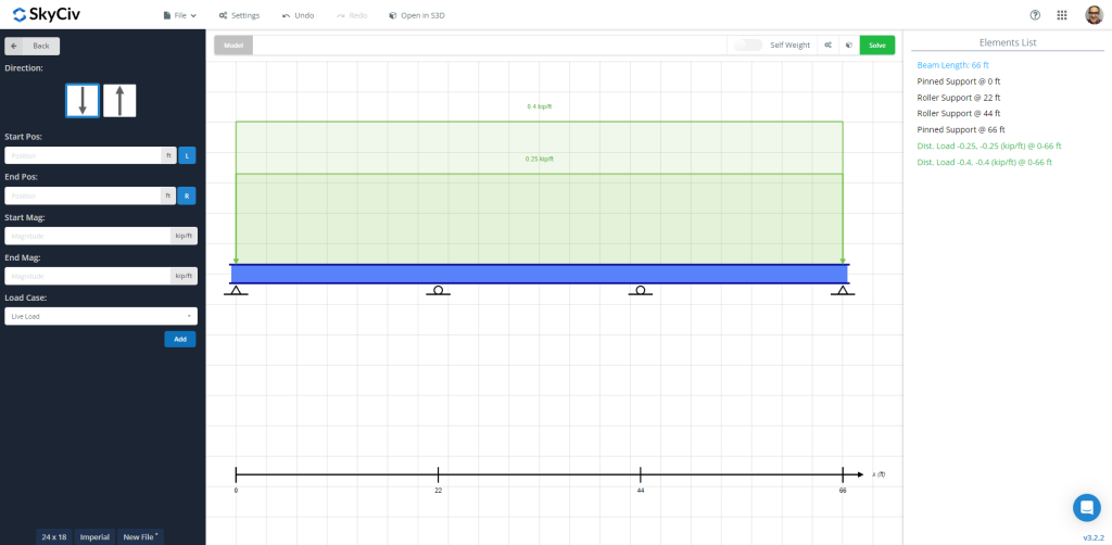
図 1: 死荷重と活荷重が適用された梁モデル
ビームを解いた後, 結果を確認できます, 曲げ図のように, 要素の長さに沿って最大値を取得するには. 次の画像は最終出力を示しています.
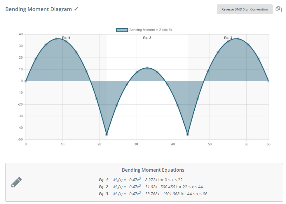
図 2: 指定された荷重の組み合わせによる曲げモーメント線図
SkyCiv Beam ソフトウェアは、力の最大値を示す表を提供します。, ストレス, と変位:
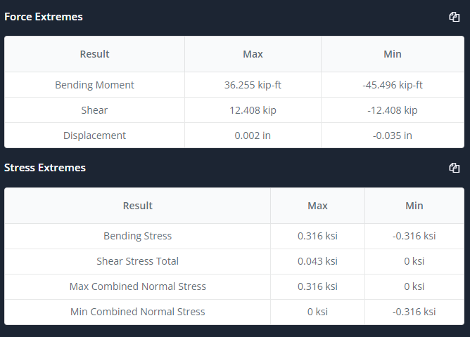
図 3: 概要表
ここで、「設計」タブを選択し、入力を鉄筋レイアウトとして選択して定義します。, 分析セクション, いくつかの係数, 荷重の組み合わせ, 等. 数字を見てください 4 そして 5 詳しい説明は.
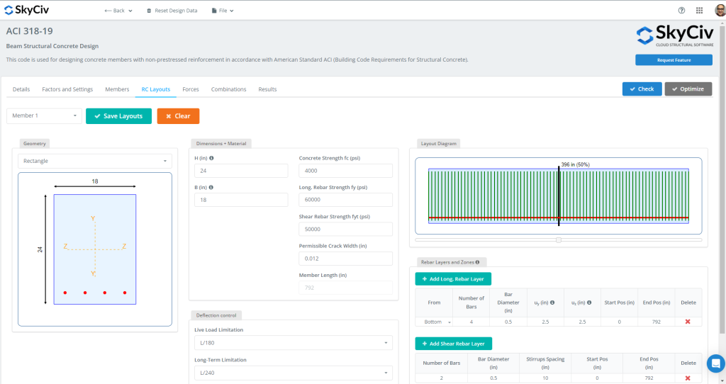
図 4: RC梁レイアウト
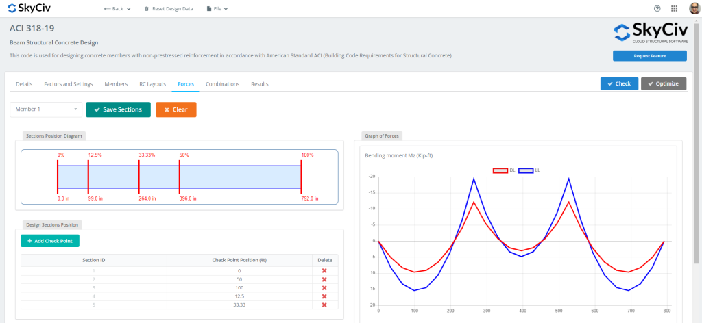
図 5: 設計時に評価する力とセクション
すべてのデータの準備ができたら, をクリックできます “小切手” ボタン. このアクションにより、結果と強度と保守性の能力比が得られます。.
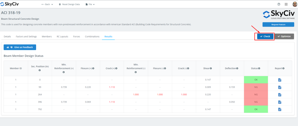
図 6: ビームモジュールの設計結果.
その後、必要なすべてのレポートをダウンロードできます。!
あなたがSkyCivで初めての場合, サインアップして自分でソフトウェアをテストする!
SkyCiv構造3D
今こそ構造 3D を使用する時です! Beam ソフトウェアに戻って、 “S3Dで開く” ボタン. これは、S3D でモデルとその入力を準備するのに役立ちます.
変更ボタンをクリックしたら, モデルは自動的に作成されました. 忘れずに保存してください! (このモジュールについてよく理解する必要がある場合, これを見てください チュートリアルのリンク!)
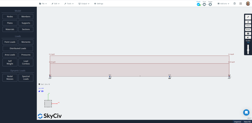
図 7: S3Dで自動作成されたモデル.
今すぐに直接アクセスしてください “解決する” アイコンを選択する “線形解析” オプション. 結果を自由に確認して比較してください; を使用します “設計” オプション. さまざまなタブでビームを評価するために必要なすべての特性を定義します。.
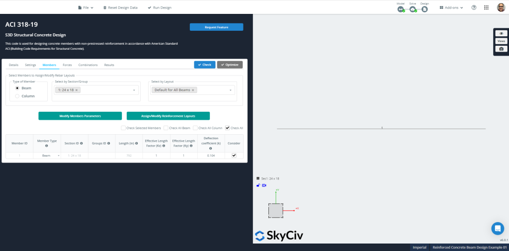
図 8: 会員’ デザインのための情報
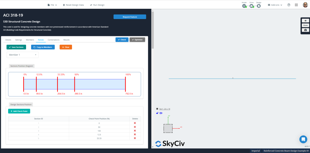
図 9: 会員’ 設計のための力と断面
SkyCiv は、特定の定義された RC レイアウトを確認したり、断面鉄筋の最適化を計算したりできます。. この後者のオプションを実行することをお勧めします.
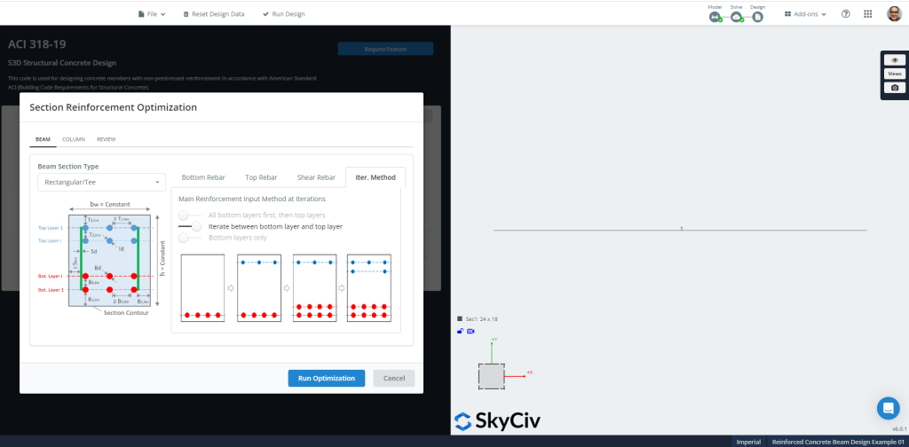
図 10: セクション鉄筋の最適化.
数字 11 そして 12 最終結果と、最適化設計用に計算された推奨セクションの補強を表示します。.
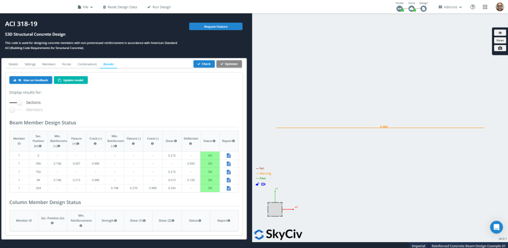
図 11: 構造コンクリート設計結果
その後、必要なすべてのレポートをダウンロードできます。!
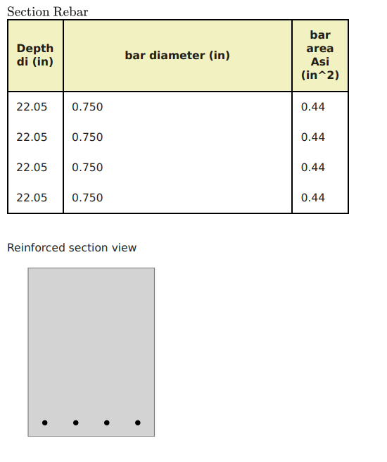
図 12: 形鋼の最適化
あなたがSkyCivで初めての場合, サインアップして自分でソフトウェアをテストする!
ACI-318 近似式
連続ビームを設計する場合, ACI-318 では、曲げ計算にモーメント係数を使用できます。. (他の例については, に関する SkyCiv の記事をぜひご覧ください。 米国および他の多くの国にとって重要な設計基準です)
クリティカルセクションでのモーメントは次のように計算されます。: \( M_u = 係数 times w_u times l_n^2 \). 係数は次から得られます。:
- 外部スパン:
- ネガティブな外装: \(\フラク{1}{16}\)
- 正のミッドスパン: \(\フラク{1}{14}\)
- ネガティブインテリア:\(\フラク{1}{10}\)
- 内部スパン:
- ネガティブ: \(\フラク{1}{11}\)
- 正のミッドスパン: \(\フラク{1}{16}\)
2つのケースを選択します: 正および負の曲げモーメントの絶対最大値.
\(wu=1.2times D + 1.6\L 倍 = 1.2 \回 0.25 + 1.6 \回 0.4 = 0.94 \フラク{キップ}{フィート} \)
\(M_{あなた,否定的} = {\フラク{1}{10}}{\回 0.94 {\フラク{キップ}{フィート}}}{\回 {(22 フィート)}^ 2} = 45.50 {キップ}{フィート} \)
\(M_{あなた,位置} = {\フラク{1}{14}}{\回 0.94 {\フラク{キップ}{フィート}}}{\回 {(22 フィート)}^ 2} = 32.50 {キップ}{フィート} \)
負モーメントの曲げ抵抗計算, \({M_{あなた,否定的} = 45.50 {キップ}{フィート}}\)
- 想定張力制御区間. \({\ファイ_f = 0.9}\)
- ビーム幅, \({b=18インチ}\)
- 鉄筋エリア, \({A_s = frac{ムー}{\phi_ftimes 0.9dtimes fy}= frac{45.50 キップフィート 回 12 -フィートで }{0.9\回 0.9(17 に )\回 60 KSI}=0.66 {に}^ 2}\)
- \({\曲げモーメントは、セクションで各方向に計算されます{分} = 0.003162}\). 鉄骨最小補強面積, \({A_{s,分}=rho_{分}\回 b回 d = 0.003162 \回 18 間に合って 17 で =0.968 {に}^ 2}\). 今, セクションが張力制御として動作しているかどうかを確認します.
- \({a = frac{A_stimes f_y}{0.85\回f'c回b} = frac{0.968 {に}^2回 60 KSI}{0.85\回 4 ksitimes 18 に }= 0.95 に}\)
- \({c = frac{a}{\beta_1}= frac{0.95 に}{0.85} = 1.12 に }\)
- \({\varepsilon_t = (\フラク{0.003}{c})\回 {(d – c)} = (\フラク{0.003}{1.12 に})\回 {(17に – 1.12 に)} = 0.0425 > 0.005 }\) OK!, テンションコントロールセクションです!.
正モーメントの曲げ抵抗計算, \({M_{あなた,位置} = 32.50 {キップ}{フィート}}\)
- 想定張力制御区間. \({\ファイ_f = 0.9}\)
- ビーム幅, \({b=18インチ}\)
- 鉄筋エリア, \({A_s = frac{ムー}{\phi_ftimes 0.9dtimes fy}= frac{32.50 キップフィート 回 12 -フィートで }{0.9\回 0.9(17 に )\回 60 KSI}=0.472 {に}^ 2}\)
- \({\曲げモーメントは、セクションで各方向に計算されます{分} = 0.003162}\). 鉄骨最小補強面積, \({A_{s,分}=rho_{分}\回 b回 d = 0.003162 \回 18 間に合って 17 で =0.968 {に}^ 2}\). 今, セクションが張力制御として動作しているかどうかを確認します.
- \({a = frac{A_stimes f_y}{0.85\回f'c回b} = frac{0.968 {に}^2回 60 KSI}{0.85\回 4 ksitimes 18 に }= 0.95 に}\)
- \({c = frac{a}{\beta_1}= frac{0.95 に}{0.85} = 1.12 に }\)
- \({\varepsilon_t = (\フラク{0.003}{c})\回 {(d – c)} = (\フラク{0.003}{1.12 に})\回 {(17に – 1.12 に)} = 0.0425 > 0.005 }\) OK!, テンションコントロールセクションです!.
最後に, どちらの瞬間でもそれがわかります, ネガティブとポジティブ, その結果、最小限の曲げ補強が割り当てられます。. 必要な鉄筋面積は次のとおりです。 \(0.968 {に}^2).
関連チュートリアル
あなたがSkyCivで初めての場合, サインアップして自分でソフトウェアをテストする!