デザインに最適化されたセクションを取得する, ワンクリックで.
SkyCiv Member Design Designer はユーザーの時間を節約します, 特定のデータベース内のすべての可能なセクションをチェックし、最小の断面積と最良の利用率を持つ形状を選択することによって. 現在, デザイナーはすべての SkyCiv デザイン コードをサポートします (AISC, NDS, AISI, なので, CSA, BS, ユーロコードなど…). デザイナーが正しく動作するには、いくつかの基準があります:
- セクションはセクション ビルダーのライブラリからロードする必要があります
- メンバーのデザイン 小切手 関数は実行できる必要があります
デザイナーは私たちの鋼鉄のすべてに存在します, SkyCiv Structural 3D による木材および冷間成形部材設計ソフトウェア, SkyCiv Beam とスタンドアロン設計ソフトウェア. 完全なビデオチュートリアルが必要です? 私たちをご覧ください チュートリアルの例 この機能について.
デザイナーの起動
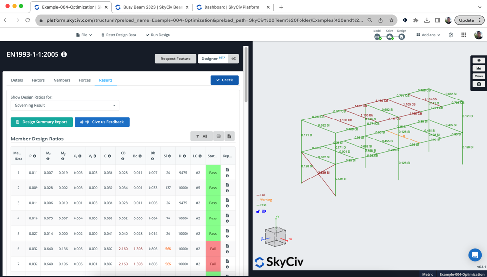
メンバーデザインを起動するには デザイナー, まず、構造を設計しているメンバー設計モジュールを開く必要があります。. この例では、ユーロコードのスチールチェックを実行しています。. モジュールが開いたら, をクリックするだけです デザイナー モジュールの右上隅にあるボタン. 以下のモデルでは, 私たちはスチールモデルを使用しています, 明らかにいくつかのユーロコードメンバーが失敗している, 彼らを通過させることができるかどうか見てみましょう:
設定モーダル
ユーザーは多数のコントロールと設定を利用できます, 目標とするユーティリティ比率を含む, セクションの高さ/幅の制限とデザインするセクション. をクリックすることで デザイナー ボタン, 次のオプションが表示されます:
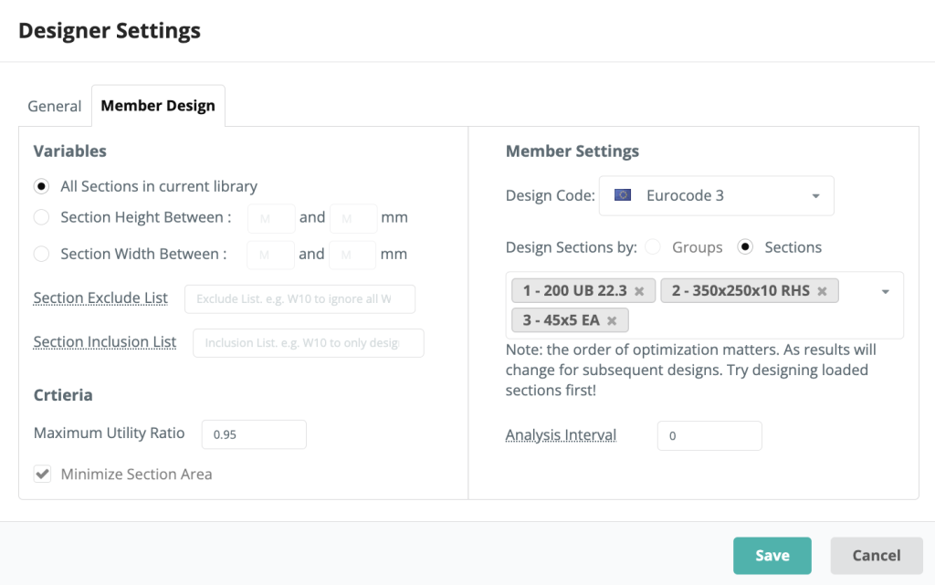
変数
ユーザーはライブラリのすべてのセクションから選択することができます。, セクションの高さまたは幅の範囲. これらのオプションはどのセクションを制御するか, 設計者は最も最適化されたセクションを選択するときに参照します。
基準
ユーザーはデザイナーに対して独自の最大使用率を入力できます, これは、指定されたよりも高い UR を持つ結果は有効な選択とは見なされないことを意味します。.
メンバー設定
設定モーダルのこの領域で, ユーザーは、メンバー設計モジュールで通常行うのと同じように、設計コードを選択できます。. モーダルは、このモジュールで設計可能なセクションもインポートします。, ただし、ユーザーはデザインしたいセクションを追加/削除することができます。. デザイナーは一度に 1 つのセクションをデザインします。.
の 分析間隔 重要な設定です, FEA ソルバーを再実行する頻度をソフトウェアに指示します。. デフォルトでは、次のように設定されています 0 – つまり、各セクションをテストするときに同じ内部力を使用します. 通常はこれで大丈夫です, 曲がった瞬間から, 断面を変更しても、せん断力と軸方向の結果はあまり変わりません. しかしながら, たわみ結果が変化し、結果に影響を与える可能性があります – 軽いセクションを使用しているため、, 自重が減るとたわみ結果を更新する必要があります.
したがって、ユーザーはテストセクション間でソルバーを実行する頻度を増やすことができます。. ここでの唯一の注意点は、プロセスが遅くなるということです, FEA ソルバーはセクションの変更の間に実行する必要があるため. 例えば, 間隔を次のように設定した場合 1, セクションテストごとに再解決されます.
デザイナーのプロセス
Designer は次のように実行されます。:
- 初期解析/設計を実行して、モデルのセットアップが正しいことを確認し、現在の結果を確認します。
- 最初のセクションのテストを開始します:
- 指定されたライブラリ内のすべてのセクションを断面積の順にランク付けします
- モデル内のセクションを変更し、解析を再実行します。 (に応じて 分析間隔 設定)
- 新しい分析結果により (曲げ, たわみなど。) ライブラリ内の次のセクションをテストします
- 結果を保存して次の分析を実行する
- スピードとパフォーマンスのために, 不要なテストはスキップされます. これらは、もし (a) 最後の 5 テストにより悪い結果が出たり、 (b) 可能な限り最良の利用率をすでに見つけています (c) 私たちはかなりの数で失敗しています, 私たちはスキップします 5 セクション
- 次のセクションから始めてください, 以前のイテレーションで更新されたセクションを使用 貫かれた
セクションの順序が重要なのはこのためです, 前のセクションの最適化で要素が軽くなった場合は、作業を進めながらモデルを更新するためです。, 後続のセクション最適化の結果に影響します。. それが役立つなら, ユーザーは、デザイナーがどのような作業を行ったかのログを確認できます。 ログの表示 結果が戻ってきたら.
場合を考えてみましょう ここで列が最初に最適化されます. 彼らは通過するかもしれない, しかし、上の梁の設計を始めると、 (おそらくそれらを厚く/重くするでしょう) その後、戻って列を再確認すると、, 彼らは失敗するかもしれない. しかしながら, 逆の順序で最適化する, この問題は起こらないはずです.
結果
各セクションの結果がポップアップに表示されます, 選択したセクションの要約, それはユーティリティ率とコミット時のオプションです. 以下の例では, 全て 3 モデルのセクションが最適化されました:

下のアイコンをクリックすると、すべての実行とその結果を詳しく見ることができます。 反復. これにより、次の実行の詳細なリストが表示されます。. 例えば, セクションの選択 2 (RHS) 以下を示します:
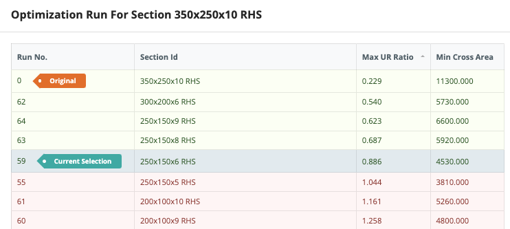
ここから最大URで並べ替えることができます, クロスエリアとSFO (加重インデックス) 事前に設定した基準に基づいて最良の結果が表示されます (設定で). これにより、ユーザーは最適化の実行をレビューして、適切なセクションが選択されていることを確認できます。. 上記の例では, 最大ユーティリティ率を設定します 0.95 断面積を最小限に抑えたいという要望. 面積を大幅に削減し、この設計基準を満たすセクションを選択しました。.
結果をコミットする
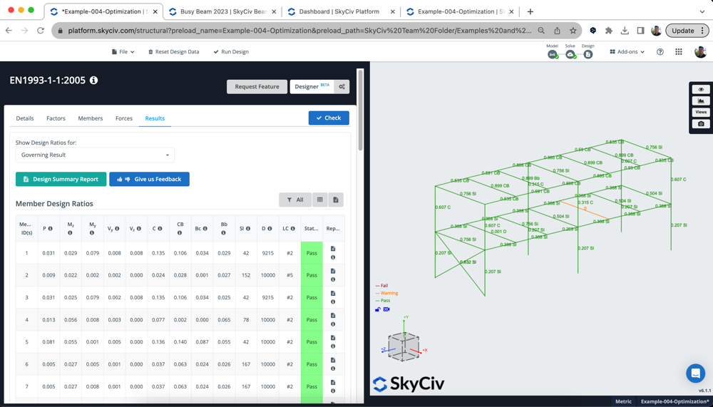
結果に満足したら, あなたは打つことができます 左側のメニューバー をクリックします 変更をコミットする それらのセクションを受け入れるには. ソフトウェアはこれらの形状を両方のデザイン モジュールにコミットします。, と構造モデル. また、ソフトウェアは設計チェックを再実行して最新の結果を提供します。. したがって、上記の例では, コミット後、セクションがすべて機能していることがわかります (過負荷だった 1 つのセクションを除いて):
デザインモードからセクションを変更する, 解析結果が現在のモデルと一致していないことを意味します. このために, 解析結果と設計結果が同期していることを確認するために、モデルに戻って解決し、設計チェックを再実行することを強くお勧めします。.
トラブルシューティング
デザイナーを実行できない場合, 次のことを確認する必要があります:
- セクションは SkyCiv セクション データベースからロードされていますか?? セクションはセクション ビルダー データベースからロードする必要があります, このようにして、デザイナーはセクションのどのカタログをテストするかを知ることができます。
- メンバーデザインを実行できますか “小切手”? これにより、セクションがすべて設計可能であり、モデルが正しく設定されていることを確認できます。. デザイナーはこれを繰り返すため、, 機能するにはベースモデルで実行する必要があります
- 何か特別な要素はありますか (先細り, 剛体メンバー)? UI はこれを防ぐ必要があります, しかし、場合によってはこれでもすり抜ける可能性があります. 設定モーダルからこれらの特別な要素を削除し、デザイナーを再度実行してください。
- 材料がテスト中の設計コードと一致していることを確認してください. 再び, これは UI によってブロックされるはずですが、場合によってはこれが発生する可能性があります。. モデルに戻り、これらのセクションが実行しようとしている設計コードと一致していることを確認します。. 例えば, NDS には適切な NDS 材料が必要です。または AISC にはセクションに割り当てられた鋼材が必要です。.
- あなたのモデルは設計標準単位系とは逆の単位系ですか?? US 設計コードをインペリアルおよび AS で実行することをお勧めします。,に,BS,CSAなど. すべてメートル単位の規格