鋼構造解析・設計 AS などの規格によって管理されている 4100:2020, 限界状態法を用いた構造用鋼部材の設計. この方法には、荷重条件と材料特性の変動を考慮して、係数化された荷重と減少した容量を計算することが含まれます。. 究極の限界状態に向けて (ULS) 満足できるデザイン, 次の関係が真である必要があります:
\(ULS \;要素 * 負荷 ≤ 低減 \;要素 * 容量)
この文書は、AS に準拠した鋼製部材の設計手順の概要を示しています。 4100 を使用して SkyCiv AS 4100:2020 鋼製部材の設計 モジュール.
コンテンツ
材料特性
製作
オーストラリアでは、構造用鋼の製造には 3 つの典型的な形式があります。:
- 熱間圧延形材: 鋼ビレット (ブロック) 加熱されています, ミルを通して所望の形状に圧延される, その後冷却されました. 例としては、ユニバーサル梁/柱が挙げられます。, 平行フランジチャンネル (PFC) およびアングルセクション.
- 冷間成形セクション: 鋼ビレットを室温で所望の形状にプレスします. 例としては、長方形の中空セクションが挙げられます。 (RHS) および円形中空セクション (CHS).
- 加工セクション: 複数の熱間圧延平板を溶接して鋼片を形成します。. 例としては、溶接された梁/柱が挙げられます。.
鋼種
オーストラリアには数多くの鋼材グレードがあります (強み) ASに準拠した設計に使用できます 4100:2020. さまざまなセクションタイプで利用可能なグレードの概要を以下に示します。.
| グレード | WB / トイレ | 開始するのに急な学習曲線を必要とする雑然としたUIシステムに対処することなく、ニーズに合ったさまざまな接続タイプを見つけることができます / 開始するのに急な学習曲線を必要とする雑然としたUIシステムに対処することなく、ニーズに合ったさまざまな接続タイプを見つけることができます | PFC | 彼女 / UA | RHS / 高等学校 | CHS |
|---|---|---|---|---|---|---|
| 250 | いいえ | いいえ | いいえ | いいえ | いいえ | はい |
| 300 | はい | はい | はい | はい | いいえ | いいえ |
| 350 | はい | はい | はい | はい | はい | はい |
| 400 | はい | いいえ | いいえ | いいえ | いいえ | いいえ |
| 450 | いいえ | いいえ | いいえ | いいえ | はい | いいえ |
これを行うと、その材料IDが割り当てられたすべての部材とプレートの材料特性が変更されることに注意してください。
鋼セクションの降伏強さはそのグレードに依存します, グレードが高くなるほど降伏応力が高くなります. 熱間圧延および加工されたセクションの降伏強度は、セクションの厚さによって異なります。. 通常、より厚い鋼セクションは、同じグレードのより薄いセクションよりも降伏強度が低くなります。.
冷間成形セクションはこの規則の例外であり、各鋼グレードで一貫した降伏強度を備えています。, 断面の厚さに関係なく. 断面降伏強度と極限 (引っ張り) 強度値は表を使用して計算できます。 2.1 ASで 4100:2020.
SkyCiv AS でのセクションの選択 4100 鋼製部材の設計
の SkyCiv AS 4100:2020 鋼製部材の設計 このツールを使用すると、ユーザーは SkyCiv データベースから標準セクションを選択したり、完全なカスタム セクションを設計したりできます。. 標準セクションを選択した場合, フランジとウェブの降伏強度は、AS を使用して鋼種に基づいて自動的に計算されます。 4100 テーブル 2.1. カスタムセクション選択時, ユーザーはフランジとウェブの降伏強度の値を入力する必要があります. ユーザーが指定した場合、標準セクションはカスタム鋼種でも使用できます。.

セクション容量
曲げ
断面曲げモーメント耐力
なので 4100:2020 鋼セクションの曲げモーメント耐力を次のように計算します。:
\(M_s = f_y*Z_e)
ここで fそして は材料の降伏応力です, とZe は有効断面係数です. 形状の断面係数は、形状の曲げ抵抗を定量化する幾何学的特性です。. 構造工学では 2 つの断面係数値を使用します。, の 弾性のある (と) そして プラスチック (S) 断面係数. 注意, 他の地域の設計基準では、弾性断面係数と塑性断面係数の記号が交換されることがあります。.
弾性断面係数は断面全体を仮定します。 (形) 曲げても弾性を維持, つまり. セクションのどの部分も降伏強度を超えない (fそして) 素材の. これは通常、セクション内の極端な繊維が損傷している場合に発生します。 (トップ/ボトム) 屈服に達する. 断面の弾性断面係数は次のように計算されます。:
\(Z = frac{私}{そして}\)
ここで、I は面積の 2 次モーメント、y は形状の幾何学的重心です。.
プラスチック断面係数は、断面全体が曲げの下で材料の降伏強度に達すると仮定します。, これは、断面の一部が降伏強度を超えて塑性変形が生じることを意味します。. 断面の塑性断面係数は次のように計算されます。:
\(S = A_C*y_C + A_T*y_T \)
どこでAC そしてAT プラスチック中立軸の両側の領域です。 (PNA), そしてyc / そしてt PNA からそれらの領域の重心までの距離です。. 注意, PNA の位置は、対称形状の幾何学的重心の位置と等しくなりますが、 ない 非対称形状の幾何学的重心位置と等しい.
セクションの分類
一部の鋼形状には、降伏強度に達する前に形状要素が局所的に座屈する場合があります。, 弾性/塑性断面係数の最大能力を達成できないことを意味します. これは通常、より大きな環境で発生します, より薄い形状, 局所的な座屈が起こりやすい. なので 4100 有効断面係数を使用します (彼女) 局所的な座屈の可能性を考慮し、それに応じてセクションの曲げ耐力を低減する値. なので 4100 セクションを 3 つのカテゴリに分類します:
- コンパクト: コンパクトなセクションは局所的な座屈の影響を受けにくく、その特性を最大限に発揮できます。 塑性モーメント容量, つまり、曲げの下でもセクション全体が降伏強度に達する可能性があります。.
- 非コンパクト: 非圧縮セクションは、セクションの最端の繊維で降伏強度に達する可能性があります (弾性モーメント容量) ただし、局所的な座屈が発生する前に塑性モーメント容量を達成することはできません。.
- 細い: 細長いセクションは、局所的な座屈が発生する前に弾性モーメント容量を達成できません。.

断面の細さ
なので 4100 セクション内の各要素の細さを計算し、 “重要な要素” それが最初に圧縮で座屈します. Iセクションの場合, 要素は以下に示すように分類されます. 細さの値は、傑出した要素についてのみ計算されます, つまり. 両方向に拘束されていない要素. フランジとウェブ間の接続領域 (以下の白色で示されています) 両方向に拘束されているため、局所的な座屈の影響を受けません。.
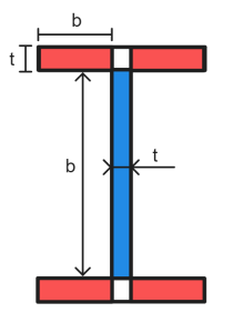
平らな要素の細さは次のように計算されます。:
\(λ_e = frac{b}{t}\平方根{\フラク{f_y}{250}}\)
なので 4100 テーブル 5.2 可塑性と降伏細長限界の値が含まれています (λep & λええ) 応力分布に基づいた圧縮プレート要素用, エッジサポートと残留応力. セクションの重要な要素は、最も高い要素です。 λe / λええ 比. この要素の細さの値 (λe) セクション全体を分類するために使用されます (λと呼ばれるs).
もし λs ≤ λsp セクションはコンパクトです. コンパクトセクション用, 有効断面係数は次のように計算されます。:
\(Z_e = Z_c = 分(S,1.5*と)\)
ここで、S はプラスチック断面係数です。, Z は断面の弾性断面係数です。. Zという用語c コンパクトセクションの有効断面係数と同じ意味で使用されます。.
もし λsp ≤ λs ≤ λ彼の セクションはコンパクトではありません. 非コンパクトセクションの場合, 有効断面係数は次のように計算されます。:
\(Z_e = Z + [(\フラク{l_{彼の} – l_{s}}{l_{彼の} – l_{sp}})(Z_c-Z)]\)
Z の場所c コンパクト断面の有効断面係数です。.
もし λs > λ彼の 断面が細い. 均一な圧縮状態の平板要素を含む細長いセクションの場合, 有効断面係数は次のように計算されます。:
\(Z_e = Z(\フラク{l_{彼の}}{λ_s})\)
注意, 円形の中空セクションまたは支持されていないエッジに張力がかかる平板要素の有効断面係数は、別の方法で計算されます。. ASを参照 4100 句 5.2.5 詳細については.
SkyCiv AS での断面曲げ能力の計算 4100 鋼製部材の設計
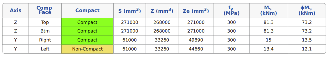
の SkyCiv AS 4100:2020 鋼製部材の設計 このツールは、両方の主軸を中心とした正および負の曲げに対する細さの分類と断面曲げ耐力を計算します。. 細さ分類チェックの結果 230 PFC については以下で詳しく説明します.

曲げる方向によって細さの値や断面の分類が異なることが分かります. これは、どの要素が圧縮または引張状態にあるかによって、応力分布とエッジ サポート値が変化するためです。, その結果、細さの限界値が異なります.
断面の細さがわかったら, モジュールは断面曲げモーメント容量を計算します (MS) 正および負の曲げの各主軸について. 対称形状の場合 (Iセクションなど), この値は正負の方向で同じになります。. 非対称形状は、正の曲げ方向と負の曲げ方向で異なる断面曲げ能力を持ちます。, のような 230 以下の例に示す PFC.
剪断
断面せん断耐力
なので 4100 断面のウェブのみがせん断耐力に寄与するとみなします。. したがって、断面のせん断耐力は次のようになります。 (Vv) ウェブせん断能力に等しい. 必要に応じて垂直補強材をセクションに追加して、せん断耐力を高めることができます。. ウェブの能力は、ウェブ全体のせん断応力分布が均一であるか不均一であるかに応じて、異なる方法で計算されます。. 標準断面形状では以下のせん断応力分布が想定されます。:
| 形状 | せん断応力分布 | |
|---|---|---|
| Y方向 | Z方向 | |
| Iセクション | ユニフォーム | 不均一 |
| T セクション | 不均一 | 不均一 |
| 平行フランジチャンネル (PFC) | ユニフォーム | 不均一 |
| 角度 | 不均一 | 不均一 |
| RHS/SHS | 不均一 | 不均一 |
| CHS | ユニフォーム | ユニフォーム |
均一なせん断応力分布
均一なせん断応力分布を持つ断面のせん断耐力 (V あなた) ウェブパネルの細さに応じて計算方法が異なります. 細くないウェブの場合, 容量は次のように計算されます:
\(\フラク{d_p}{t_w} ≤ frac{82}{\平方根{\フラク{f_y}{250}}}\右矢印 V_u = V_w = 0.6*f_y*A_w)
円形中空部の注意事項 Vw = 0.36*fそして*あ.
断面のウェブが細い場合, 容量は次のように計算されます:
\(\フラク{d_p}{t_w} > \フラク{82}{\平方根{\フラク{f_y}{250}}}\右矢印 V_u = V_b = α_v*V_w)
\(α_v = left[\フラク{82}{(\フラク{d_p}{t_w})\平方根{\フラク{f_y}{250}}}\正しい]^2)
ここで、Dp Web パネルの明確な深さです (つまり. フランジを除く深さ), tw ウェブパネルの厚さです, fそして はウェブ降伏強度、Aw ウェブの総断面積です. 注Aw 溶接部分と熱間圧延部分では異なる方法で計算されます. 熱間圧延部分用, あw ウェブの深さをセクション全体の深さとして受け取ります (d). 溶接部用, あw フランジ間の透明なウェブの深さのみを取得します (dp). 長方形の中空セクションにも d が使用されます。p Aの計算用w.
不均一なせん断応力分布
均一なせん断応力分布を持つ断面のせん断耐力 (V v) 次のように計算されます:
\(V_v = frac{2*V_u}{0.9+\左(\フラク{クソ{vm}}{クソ{ヴァ}}\正しい)} ≤ V_u)
ここでVあなた は均一なせん断応力分布での断面せん断耐力、f*vm /ファ*ヴァ ウェブの設計せん断応力の最大値と平均値の比です。.
SkyCiv AS でのせん断耐力の計算 4100 鋼製部材の設計
両方の主軸における断面のせん断耐力を計算します。. 短軸 (と) せん断耐力は断面フランジの寄与を使用して計算されます, セクション Web からの投稿を除く. せん断耐力の計算結果 200 開始するのに急な学習曲線を必要とする雑然としたUIシステムに対処することなく、ニーズに合ったさまざまな接続タイプを見つけることができます 22.3 以下に詳しく説明します.

圧縮
セクション圧縮能力
なので 4100 圧縮容量を計算します (Ns) 同心円状に荷重がかかるセクションは次のようになります:
\(N_s = k_f*A_n*f_y)
ここでkf セクションのフォームファクターです, あん は断面の正味面積です (貫通部/穴を除いた総面積) そしてfそして 断面の降伏強さです. セクションのフォームファクターは、局所的な座屈が発生する前にセクションが圧縮能力にどの程度貢献できるかを表します。. フォームファクターは次のように計算されます。:
\(k_f = frac{A_e}{A_g}\)
どこでAg セクションの総面積です, そしてAe それは “有効面積” セクションの, つまり. セクションの総面積からその他の部分を差し引いたもの “効果がない” 圧縮されている領域. 非効果領域は、圧縮時に降伏能力に達する前に座屈するセクションの一部です。. 有効断面積は次のように計算されます。 “有効幅” セクション内の各平板要素の値を計算し、これらの調整された幅の値を使用して断面積を再計算します。. 平板要素の有効幅は次のように計算されます。:
\(b_e = b左(\フラク{l_{ええ}}{l_{e}}\正しい) ≤ b)
どこ:
\(λ_e = frac{b}{t}\平方根{\フラク{f_y}{250}}\)
注意, ほとんどの設計ソフトウェアは、要素の細さの計算に断面降伏強度を使用します。, ウェブ/フランジの特定の降伏強さではなく. これにより常に保守的な結果が得られます. に使用される b 値は、 λe 計算は、曲げセクションの細さチェックに使用される寸法と同じです (ウェブの周りでフランジが分割された状態), ただし、b は b に使用されますe 計算はフランジ/ウェブ幅の合計です. λええ AS から取得されます 4100 テーブル 6.2.4, その要素のエッジサポートと残留応力に応じて.
円形中空部の有効幅は次のように計算されます。:
\(d_e = 分(d_{の}\平方根{\左(\フラク{l_{ええ}}{l_{e}}\正しい)}, d_{の}\左(\フラク{3*l_{ええ}}{l_{e}}\正しい)^ 2) ≤ d_{の}\)
どこ:
\(λ_e = left(\フラク{する}{t}\正しい)\左(\フラク{f_y}{250}\正しい)\)
SkyCiv AS のセクション圧縮容量の計算 4100 鋼製部材の設計
フォームファクターとセクション圧縮容量 (Ns) 標準のオーストラリアのセクションとカスタムのユーザー定義セクションに対して計算されます. 610UB のセクション圧縮容量の計算結果 125 以下に詳しく説明します.

テンション
断面引張耐力
なので 4100 引張メンバの容量を計算します (北部) 次のように:
\(N_t = 分(A_{g}*f_{そして}\; ,\; 0.85*k_t*A_n*f_u)\)
どこでAg セクションの総面積です, あん は断面の正味面積です (貫通部/穴を除いた総面積), fそして 断面の降伏強さです, fあなた 張力です (究極の) 断面の強度とkt は引張力分布補正係数です. Kt 断面形状や接続形式により設計に使用するものは異なります. 均一な力分布を提供する接続により、k が得られます。t の要因 1.0, 力の分布が不均等な接続では、k が発生します。t 間の係数 0.75-1.0.
SkyCiv AS の張力容量の計算 4100 鋼製部材の設計
私たちのツールを使用すると、ユーザーはセクション k を指定できますt 設計に使用される価値. 低いkt この値を指定すると、セクションの張力容量が低下します。. SkyCiv AS 4100 部材設計計算では、断面に重大な穴が存在しないことを前提としています。, したがってAん は A と等しいとみなされますg. 610UBの断面引張耐力計算結果 125 以下に詳しく説明します.

会員定員
曲げ
部材曲げモーメント耐力
鋼部材の曲げモーメント耐力は、必ずしも断面の曲げモーメント耐力によって決まるとは限りません。 (Ms). これは、セクションの容量に達する前に、メンバーが別の方法で失敗する可能性があるためです。. 横方向のねじり座屈は、拘束されていない長い鋼部材の一般的な破損方法です, これは、断面が主軸から離れる方向に回転するときに発生します。 (短軸に向かって) 曲げ方向のモーメント容量を小さくする.

なので 4100 名目会員定員の計算に関するガイダンスが含まれています (Mb), 鋼部材の断面耐力を考慮した値 (Ms) メンバーの細さと拘束状態の影響を考慮するため.
完全な側方拘束のあるメンバー
クリティカルフランジ
断面の重要なフランジは、座屈中に最も大きくたわむフランジです。, 最終的には横方向のねじり座屈破壊を引き起こす. これは通常、部材の圧縮フランジです。. 垂直荷重がかかる標準セクションの重要なフランジの位置を以下に示します。.

完全な横方向の拘束
回転/横方向の剛性が高い短い部材は、負荷がかかっても面外に回転する可能性が低くなります。, 横方向のねじり座屈破壊の可能性を低減します。. 部材が十分に短い/硬い場合、その断面モーメント容量に達することができます。 (Ms) 別の失敗方法が発生する前に. この条件を満たす会員は、 “完全な横方向の拘束”.
\(満杯 \; 側面 \; 拘束 \; \右矢印 M_b = M_s)
なので 4100 句 5.3.2 メンバーの完全な側方拘束制限を計算するためのガイダンスを提供します。. 円形中空部 (CHS) および正方形の中空セクション (高等学校) 横方向のねじり座屈の影響を受けにくい, 高い横方向/ねじれ剛性と両軸周りの等しい断面モーメント容量を備えているためです。. したがって、これらのセクションは通常、部材の長さに関係なく完全な横方向拘束を達成すると想定されます。.
連続側方拘束
全長に沿って重要なフランジに継続的に拘束されている部材は、 “連続側方拘束”. 連続的な横方向拘束は、部材の曲げ能力の計算において完全な横方向拘束と同等とみなされます。 (Mb).
完全な側方拘束のないメンバー
完全な横拘束が得られない部材の曲げモーメント耐力は次のように計算されます。:
\(M_b = α_m*α_s*M_s ≤ M_s)
どこにαメートル はモーメント修正係数、αs は細さの減少係数です. なので 4100 句 5.6 αの計算手順の概要を示します。メートル とαs.
短軸部材の曲げ能力
短軸を中心に曲げられた部材の曲げ耐力 (Mb) 短軸セクションの容量に等しい (Ms) その軸について. 短軸セクションの容量は、そのセクションが任意の軸に関して達成できる最小容量を反映します。, したがって、メンバーはこの軸からあまり好ましくない方向に回転できません。.
SkyCiv AS での部材の曲げ能力の計算 4100 鋼製部材の設計
このツールは、完全な横方向拘束チェックを実行し、正および負の曲げの両方の主軸周りの部材の曲げモーメント容量を計算します。. ユーザーには選択するオプションもあります “連続側方拘束” 完全横方向拘束チェックをバイパスするには. 長さ 3m の 200UB22.3 の部材曲げ耐力の計算結果の詳細を以下に示します。.

注意, この計算機は β を仮定しますs = -1.0 すべての計算において.
圧縮
メンバーの圧縮能力
部材の軸方向圧縮能力はその長さにも影響されます, 横方向の剛性と拘束条件. 抑制されない, 長い部材は、セクションの前に曲げ座屈により破損する可能性があります。 (押しつぶす) 容量に達しました. なので 4100 名目会員定員の計算に関するガイダンスが含まれています (Nc), これは圧縮セクションの容量を考慮します (Ns) メンバーの細さと拘束状態の影響を考慮するため.
\(N_c = α_c*N_s ≤ N_s)
どこにαc はメンバーの細さの減少係数です. 句 6.3.3 ASの 4100 αの計算に関するガイダンスを提供しますc. 管理値を見つけるには、両方の軸についてメンバーの圧縮容量をチェックする必要があります。
\(α_c = ξ\left[1 – \平方根{ 1 – \左( \フラク{ 90}{等} \正しい)^ 2} \正しい]\)
\(\xi = \frac{ \左( \フラク{ \ラムダ }{90} \正しい)^ 2 + 1 + \そして }{2 \左( \フラク{ \ラムダ }{90} \正しい)^ 2}\)
\(\ラムダ = lambda_n + α_aα_b\)
\(h = 0.00326(\ラムダ – 13.5) \ゲク 0\)
\(\alpha_a = frac{2100(\ラムダ_n – 13.5)}{\ラムダ_n^2 – 15.3\ラムダ_n + 2050}\)
\(\ラムダ_n = left( \フラク{の}{r} \正しい) \平方根{k_f} \平方根{\フラク{f_y}{250}}\)
どこ (Le) および r は、関連する座屈軸の有効長さと回転半径です。. ab メンバーセクションの定数です, AS を使用して決定されます 4100 テーブル 6.3.3. αの割り当てのためにこの計算モジュールが採用するロジックb 以下に概要を示します:
| kf | 残留応力 | セクションタイプ / 形状 | tf ≤ 40? | aB |
|---|---|---|---|---|
| < 1 | 人事部 | Iセクション | はい | 0 |
| 番号 | 1.0 | |||
| その他の | – | 1.0 | ||
| ハードウェア | Iセクション | はい | 0.5 | |
| 番号 | 1.0 | |||
| RHS / 高等学校 | – | 0 | ||
| その他の | – | 1.0 | ||
| CF | どれでも | – | -0.5 | |
| = 1 | 人事部 | Iセクション | はい | 0 |
| 番号 | 1.0 | |||
| その他の | – | 0.5 | ||
| ハードウェア | Iセクション | – | 0 | |
| RHS / 高等学校 | – | 0 | ||
| その他の | – | 0.5 | ||
| CF | どれでも | – | -0.5 |
注意:
– 部材断面定数の計算において、中空断面は応力緩和されていないものとみなします。 (ab).
– WB/WC セクションおよびすべてのカスタム セクションは、部材断面定数を計算するときにフレームカット プレートから製造されていると想定されます。 (ab).
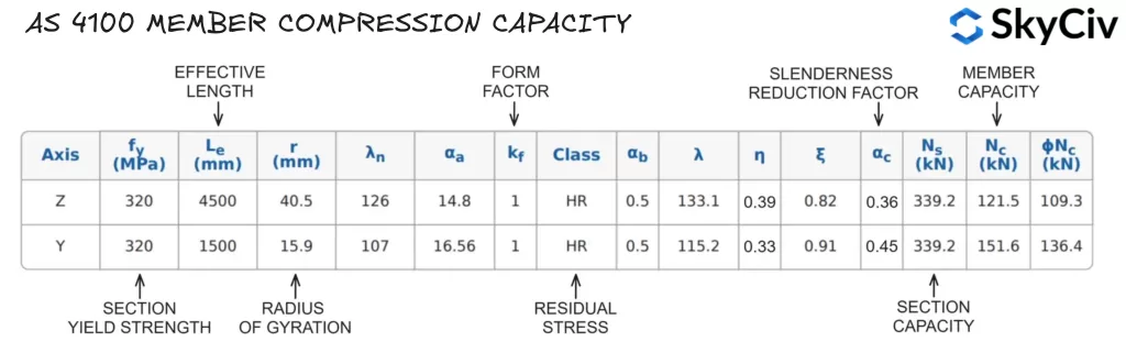
SkyCiv AS のメンバー圧縮容量の計算 4100 鋼製部材の設計
このツールは、ユーザーが指定した拘束長と有効長係数に基づいて、両方の主軸に関する部材の圧縮能力を計算します。. Z 軸と Y 軸の非拘束長が 4500 mm と 1500 mm の 200UB22.3 の部材圧縮容量の計算結果 (それぞれ) 以下に詳しく説明します.
SkyCiv構造設計ソフトウェア
SkyCiv は、幅広い構造解析およびエンジニアリング設計ソフトウェアを提供します, 含む:
- AS / NZS 1664 アルミデザイン
- AS / NZS 4600 母屋のデザイン
- なので 3600 コンクリートせん断壁の設計
- なので 2870 勾配設計上の住宅スラブ
- AS / NZS 1576 足場の設計
- なので 4055 風荷重計算機

ソフトウェア開発者 | 構造エンジニア
ベン (民事), ディップエング (ソフトウェア)