
せん断接続とは?
せん断接続は、意味のあるモーメントを伝達せずに 2 つの部材間にせん断力を伝達するジョイントです。. ビームが内部を伝送する場合 剪断力, その力は接続部を通って支柱に伝わります。 軸力. せん断接続はピンとして動作します (SkyCiv 構造 3D の FFFFFR), とは異なり モーメント接続, 最後の回転を保持する.
AISC内 360-16 これは条件です 単純 繋がり (B3.4): 自由に回転し、モーメントは無視できると仮定されます. なので 4100:2020 等価配置を単純構造と呼ぶ. 半剛体ジョイントは 3 番目のケースです, 実際の、しかし部分的な回転剛性を伴う, そしてそれを単純なものとして扱うのではなく、そのようにモデル化する必要があります.
プレートまたはアングルは 2 つの部材間に力を伝達します. 上の例では, ビームにかかる下向きの荷重は角度を通って支持部材に伝わります。. ビームフランジを拘束するものがないため, ジョイントは回転できます, これがモーメント結合ではなくせん断結合となる理由です.
せん断接続 鉄骨フレームで最も一般的な接続です. フレームが固定されている場所, ブレースは横方向の安定性を提供します, したがって、モーメント接続はフレームがフレームアクションに依存する場合にのみ必要です。. そのため、ほとんどの設計者は、解析が可能な場合はどこでもせん断結合に手を伸ばします。: 製造が簡単で、組み立ても安価です.
Shear connection design comes down to following the beam reaction from the beam web, ボルトを通して, plate or angle and welds, into the support, and checking every part it passes through. This page sets out that procedure with the AISC 360-16 方程式, and links to five fully worked AISC calc sheet examples that apply it to real connections.
SkyCiv 接続設計は、せん断接続をチェックします AISC 360-16 ASDとLRFDの両方で, そしてへ なので 4100:2020.
せん断接続の種類
せん断接続は、荷重を支えるコンポーネントとその設置場所にちなんで名付けられています。. どのものが利用できるかは、設計コードとビームが何にフレームされるかによって異なります。, したがって、以下のリストはそのように分割されています.
梁から I 断面柱まで, またはビームからビームへ (AISC 360-16)
6つの構成, 柱フランジに利用可能な各フレーム, コラムウェブへ, またはウェブを介したビームツービーム:
- シングルアングル. ビームウェブとサポートの間に 1 つの L 字型ブラケット. 最も軽いオプション, そして最も柔軟な, 軽い荷物に適しています. The reaction sits off the support-side bolt line, so those bolts carry an eccentricity (作業例).
- ダブルアングル. ビームウェブの両面の角度. The extra angle puts the beam-side bolts in double shear and makes the connection more forgiving during erection, それがより重いビームの主力製品である理由です (作業例).
- シングルプレート. シアータブ. 一皿, サポートに工場溶接され、ビームウェブにボルトで固定されています. 通常、グループ内で最も安い, ウェルド ラインとボルト グループが 1 つずつあるため、 (作業例). When the plate has to reach past the column flanges into a column web, it becomes an extended single plate, which is designed differently (作業例).
- ダブルプレート. ウェブの両面にプレート, 単一のプレートでは剪断力を保持できない、または必要なボルト グループを取り付けることができない場合に使用されます。.
- エンドプレート. ビーム端に溶接され、サポートにボルトで固定されたプレート. ビームを正確な長さに切断する必要があります, プレートには調整が残されていないため、 (作業例).
- 直接溶接ウェブ. ビームウェブはサポートにまっすぐに溶接されています, 中間プレートやアングルなし. 確認するボルトはありません, しかし、現場溶接が必要であり、ボルト締めの詳細が提供する組み立て公差を放棄します。.
ビームから HSS カラムへ (AISC 360-16)
中空セクションにフレームを入れると、適合するものが変わります, ボルトを固定するフランジがなく、レンチを使用するための反対側にアクセスできないためです。. 5 つの構成が利用可能:
- シングルアングル そして ダブルアングル
- シングルプレート
- シングルWT. ワイドフランジから切り出したティー, ステムは梁のウェブに溶接またはボルトで固定され、フランジは柱面に固定されます。.
- シート角度. ベアリング内のビームを支える底部フランジの下の角度, 通常は安定性を高めるために上部クリップが付いています. Web接続型とは異なります, これはフランジからでも機能します.
なので 4100:2020
オーストラリアの規格は、梁から I 柱へのフレーム構成と梁から梁へのフレーム構成をカバーしています。, 4つの構成で:
なので 4100 カバレッジはシアーのみです, HSS 列には拡張されません, チャネル, ブレースまたはスプライス. それがAISCです 360-16.
How to design a shear connection to AISC 360-16
Every shear connection is designed the same way: take the factored beam end reaction, [mathin] R_{u} [mathin] (または [mathin] R_{a} [mathin] for ASD), and check each part of the load path against it. The reaction leaves the beam web, passes through the beam-side bolts or welds into the plate or angles, and then through the support-side bolts or welds into the column or girder. A failure anywhere along that path is a failure of the connection.
以下の方程式は AISC の LRFD 形式です。 360-16 およびAISCマニュアル第15版. ASDの場合, 交換する [mathin] \phi R_{n} [mathin] と [mathin] R_{n} / \Omega [mathin], を使用して [mathin] \Omega [mathin] 同じ条項に記載されている ([mathin] \Omega = 2.00 [mathin] どこ [mathin] \phi = 0.75 [mathin], そして [mathin] \Omega = 1.50 [mathin] どこ [mathin] \phi = 1.00 [mathin]).
1. ディテールの制限 (J3.3, J3.4)
強度チェックの前に, the geometry has to be buildable and match the assumptions behind the strength equations. ボルトには最小限の間隔とエッジ距離が必要です, レンチを回すにはスペースが必要です, and the plate or angle should be at least half the beam’s T dimension deep so the beam end stays stable. 最小ボルト間隔は次のとおりです。:
[math] s_{min} = 2\tfrac{2}{3}\, d_{b} \qquad (3\, d_{b}\ \text{preferred}) [math]
Minimum edge distances come from Table J3.4, with an increment from Table J3.5 when the edge is measured across a slotted hole. In the worked examples a detailing limit is often the highest ratio in the whole connection. That is normal: designers lay the bolts out at the limits to keep the plate small.
2. Bolt shear and eccentricity (J3.6, マニュアル部分 7)
The strength of one bolt in shear is:
[math] \phi r_{v} = \phi\, F_{nv}\, A_{b}\, N_{s} = \phi\, F_{nv}\, \frac{\pi}{4} d_{b}^{2}\, N_{s}, \qquad \phi = 0.75 [math]
どこ [mathin] F_{nv} [mathin] comes from Table J3.2 (54 ksi for A325-N and 68 ksi for A490-N, grades within ASTM F3125) そして [mathin] N_{s} [mathin] is the number of shear planes. The bolts in a double angle beam-side group are in double shear, [mathin] N_{s} = 2 [mathin].
The reaction rarely acts on the bolt line. When it sits a distance e away, the bolts carry a moment [mathin] R_{u}\, e [mathin] as well as the shear, and the group delivers fewer than n bolts’ 強さの価値がある. 瞬間の回転中心 (ICOR) method finds that reduced count, the coefficient C, from the load-deformation curve of each bolt (マニュアルEQ. 7-1):
[math] R = R_{ult} \left( 1 – e^{-10\Delta} \right)^{0.55} [math]
[math] \phi R_{n} = C\, \phi r_{v} [math]
How much eccentricity to design for depends on the connection type, and this is where the five worked examples differ most:
| 繋がり | 設計偏心 | Effect in the worked example |
|---|---|---|
| 単板 (conventional) | [mathin] e = a/2 [mathin] from Manual Table 10-9 | 2 in to the bolt line becomes e = 1 に; three bolts give C = 2.71 |
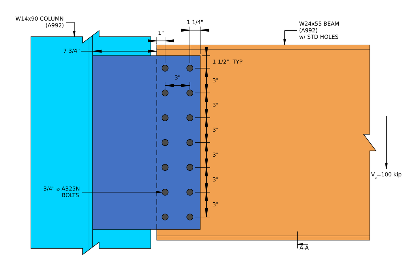
| Extended single plate | Full distance from the weld to the bolt group | e = 10.25 in cuts 14 ボルトで締める 6.29 effective bolts |
| 単一アングル, サポート側 | [mathin] e = g + t_{w}/2 [mathin], from the support bolt line to the middle of the beam web | e = 1.85 in cuts 2 ボルトで締める 1.24 ボルト’ worth |
| ダブルアングル, 梁側 | Neglected (マニュアル部分 10) | The bolt group is treated as concentric |
For the iteration itself, 見る ICOR を使用したボルト グループの計算, or run a bolt group in the ボルト計算機.
3. ボルトベアリングとティアアウト (J3.10)
Each bolt pushes on the edge of its hole. The ply either crushes locally around the hole (ベアリング) or tears a strip out to the next hole or the edge (引き裂く). With deformation at service load a design consideration:
[math] \phi r_{n} = \phi\, \min\left( 1.2\, l_{c}\, t\, F_{u},\ 2.4\, d_{b}\, t\, F_{u} \right), \qquad \phi = 0.75 [math]
[math] l_{c1} = L_{e} – \frac{d_{h}}{2} \qquad l_{c2} = s – d_{h} [math]
The edge bolt has the short clear distance [mathin] l_{c1} [mathin], so tear-out usually limits it, while the inner bolts reach the 2.4 d t Fあなた ベアリングキャップ. Check every ply: the plate or angles, and the beam web. A thin beam web is often the weak ply, because the angles or plate are sized independently. In the double angle example the two 1/4 in angles give 0.5 in of steel against the bolts, しかし 1/4 in beam web has only one ply, and bearing on the web is the highest strength ratio, で 0.760.
Each bolt then delivers the least of its shear, bearing and tear-out strengths, グループの強さは合計です (J3.6 解説):
[math] \phi R_{n,eff} = \frac{C}{n} \sum_{i=1}^{n} \min\left( \phi r_{v},\ \phi r_{n,plate,i},\ \phi r_{n,web,i} \right) [math]
4. ブロックせん断 (J4.3)
A block of the plate, angle or coped beam web can tear out around the bolt group: shear along the line of holes plus tension across to the free edge, usually an L-shaped block.
[math] \phi R_{n} = \phi \left( 0.6\, F_{u} A_{nv} + U_{bs} F_{u} A_{nt} \right) \le \phi \left( 0.6\, F_{y} A_{gv} + U_{bs} F_{u} A_{nt} \right), \qquad \phi = 0.75 [math]
[mathin] U_{bs} = 1 [mathin] when the tension stress is uniform, which is the case for a single line of bolts. The net areas deduct each hole at [mathin] d_{h} + 1/16\,in [mathin] for damage during punching (B4.3). In the shear end plate example, block shear of the plate is the second highest ratio, で 0.920.
5. Shear yielding and shear rupture (J4.2)
The plate or angles carry the whole reaction in shear, across the gross section (譲る) そして穴を通ってネットセクションを横切る (破裂):
[math] \phi R_{n} = \phi\, 0.6\, F_{y}\, A_{gv}, \qquad \phi = 1.00 [math]
[math] \phi R_{n} = \phi\, 0.6\, F_{u}\, A_{nv}, \qquad \phi = 0.75 [math]
In the single plate example, せん断破断 1/2 in plate is the highest load check, で 0.629.
6. Plate flexure and the shear-flexure interaction
The reaction acts at a distance from the support, so a single plate is a short cantilever. SkyCiv checks it with the Manual’s double-coped beam procedure, which treats the plate like a beam web coped top and bottom, and checks flexural rupture on the net section through the holes. Because the same section carries shear and moment, the two combine:
[math] \left( \frac{V_{u}}{\phi V_{n}} \right)^{2} + \left( \frac{V_{u}}{\phi R_{n}} \right)^{2} \le 1.0 [math]
This check grows with the eccentricity. In the conventional shear tab it is minor, but in the extended single plate example the rupture interaction governs the connection at 0.938.
7. 延性: the maximum plate thickness (マニュアル部分 10)
A shear connection is assumed to rotate. プレートの曲げがボルトのせん断よりも強い場合, the bolts break before the plate yields, which is a brittle failure and contradicts the simple connection assumption. The Manual caps the plate thickness so the plate yields first:
[math] M_{max} = \frac{F_{nv}}{0.90}\, \frac{\pi}{4} d_{b}^{2}\, C’ [math]
[math] t_{max} = \frac{6\, M_{max}}{F_{y}\, d_{p}^{2}} [math]
C’ is the bolt group coefficient for moment alone. This is the one check that a thicker plate makes worse. In the single plate example a 1/2 in plate sits at 0.966 of its limit.
8. Weld strength and the base metal limit (J2.4, マニュアル部分 9)
The fillet welds that join the plate or angles to the support (or the end plate to the beam web) carry the reaction along their length:
[math] \phi R_{n} = \phi\, 0.6\, F_{EXX}\, \frac{\sqrt{2}}{2}\, w\, L_{w} \left( 1 + 0.5\, \sin^{1.5}\theta \right), \qquad \phi = 0.75 [math]
For a vertical reaction on vertical welds, [mathin] \theta = 0 [mathin] and the directional factor is 1.0. The steel either side of the weld also limits how much of the weld size counts. For welds on both faces of a plate of thickness t, 16 分の 1 で使用可能なサイズは:
[math] D_{max} = \frac{ \frac{t}{2}\, F_{u} }{3.09\,kip/in} [math]
So a bigger weld does not always help. In the shear end plate example the 0.355 in beam web limits the usable weld to about 0.233 に, and the weld governs the connection at 0.995. For a single plate, the Manual also asks for fillets of [mathin] \frac{5}{8}\, t_{p} [mathin] 両側に, so that the weld can develop the plate if it yields. サイズを試してみてください 溶接計算機.
9. The supporting and supported members
The connection is only as good as the steel it attaches to. A coped beam has a reduced section at the cope, which needs its own block shear, shear and flexure checks; the single angle example works these through for a W12x14 coped at the top flange. Where the beam frames into a girder web or a thin column web, check bearing and tear-out on that web too.
Shear connection design examples (AISC 360-16 LRFD)
以下の各例は、SkyCiv Connection Design の完全な AISC 計算シートです。, すべての方程式を段階的に書き出す, 置換値と DCR. They show how the governing check moves from one connection type to the next.
| 例 | メンバーと負荷 | 繋がり | Governing load check |
|---|---|---|---|
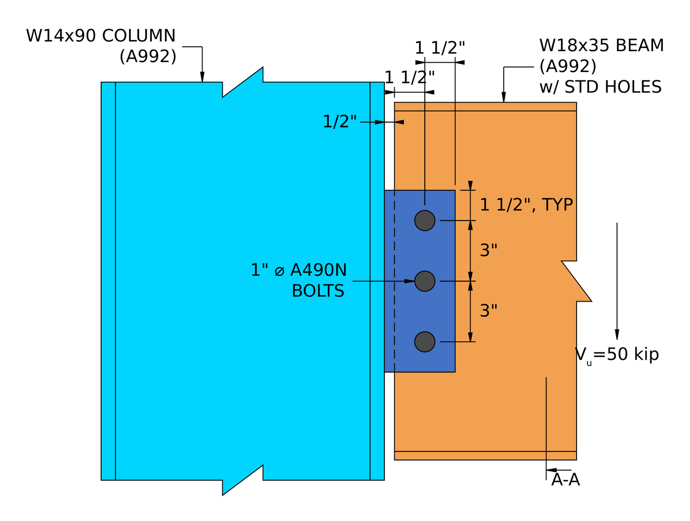
| 単板 (シアータブ) | W18x35 beam to W14x90 column flange, 50 キップ | 1/2 皿の中, 三つ 1 A490-Nボルトで | Plate shear rupture, 0.629 |
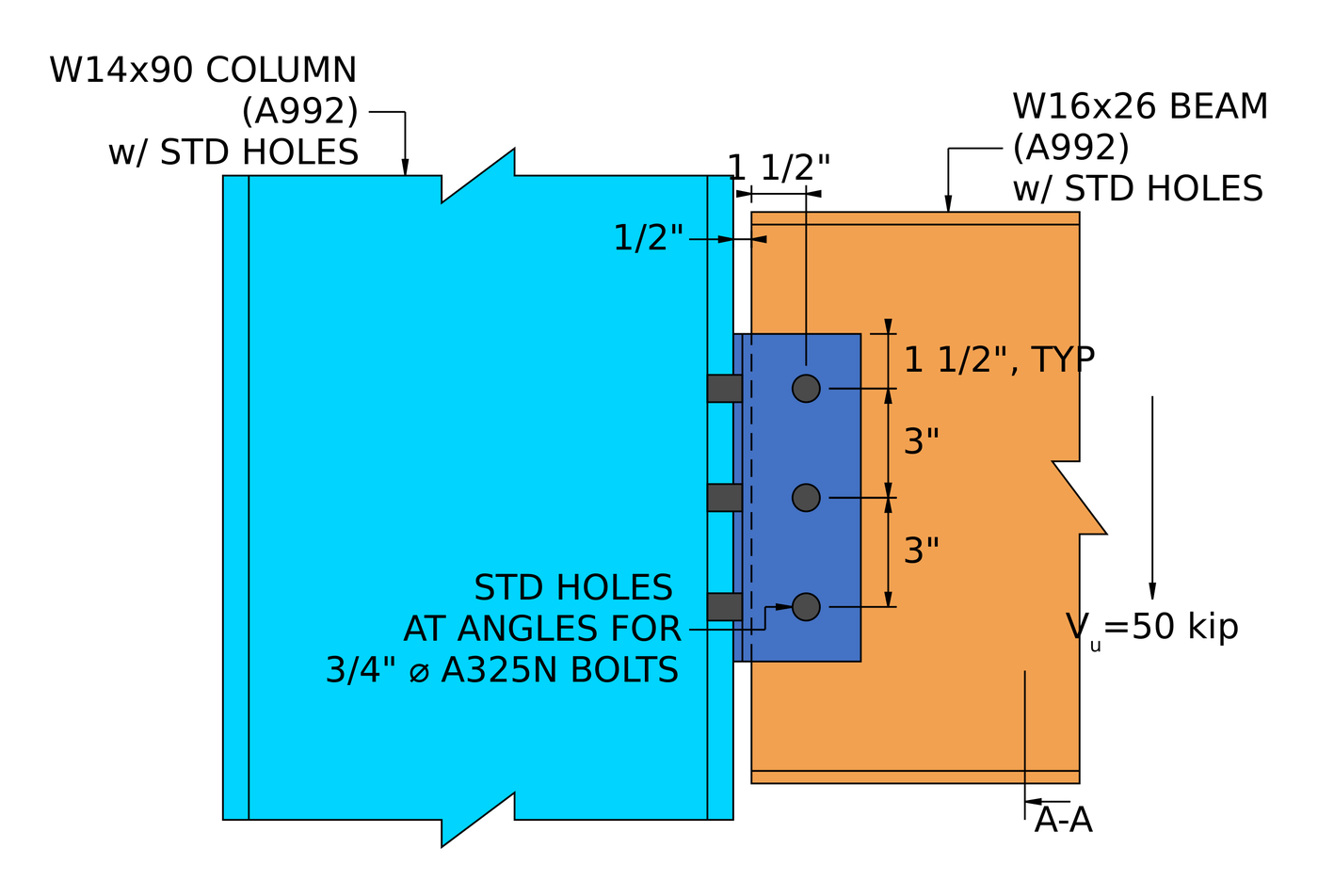
| ダブルアングル | W16x26 beam to W14x90 column flange, 50 キップ | 2L4x3-1/2×1/4, three rows of 3/4 in A325-N each side | ビームウェブ上のボルトベアリング, 0.760 |
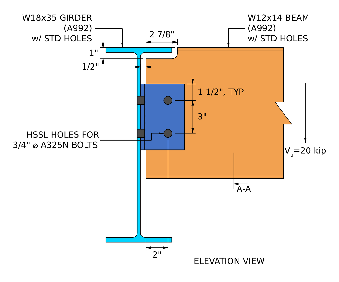
| 単一アングル | Coped W12x14 beam to W18x35 girder web, 20 キップ | L4x3x3/8, two rows of 3/4 in A325-N each leg | Bolt shear at the girder, 0.901 |
| Extended single plate | W24x55 beam to W14x90 column web, 100 キップ | 3/8 バツ 13 バツ 21 A36プレート入り, 14 3/4 A325-Nで | せん断と曲げの相互作用 (破裂), 0.938 |
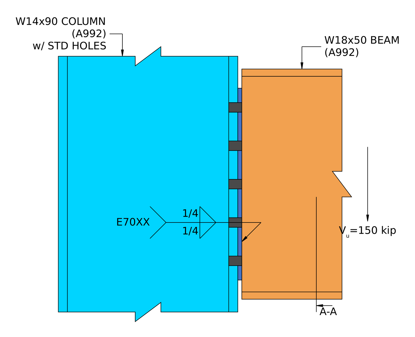
| Shear end plate | W18x50 beam to W14x90 column flange, 150 キップ | 5/16 バツ 8 1/2 バツ 15 A36プレート入り, ten 3/4 A325-Nで, 1/4 in fillets | Weld at the beam web, 0.995 |
パターンは知っておく価値があります. A short, conventional shear tab is rarely close to its limit. Once the reaction moves away from the bolts, as in the single angle and the extended plate, the eccentricity drives the design. And in a welded connection like the end plate, the thinnest piece of base metal decides the weld.
For the theory behind all five, 見る AISC を使用した鋼製接合の設計 360-16.
Which shear connection should you use?
| 繋がり | こんな方に最適 | 注意してください |
|---|---|---|
| 単板 (シアータブ) | Most beam-to-column and beam-to-girder framing. One shop weld, one field bolt group | プレートの延性 (t最高), and the Table 10-9 limits on the conventional configuration |
| Extended single plate | Framing into a column web between the flanges, without coping the beam | Full eccentricity, plate flexure and the shear-flexure interaction |
| ダブルアングル | Heavier reactions, and erection where the beam needs to be dropped in between supports | Bearing on a thin beam web, and two bolt groups to detail |
| 単一アングル | Light reactions, and access from one side only | Eccentricity at the support bolts, which cuts the group strength |
| Shear end plate | Shop-welded beams with fast, オールボルト締めの現場施工 | 正確なビーム長さ, and the weld limited by the beam web thickness |
ソフトウェアは何をチェックしますか?
せん断接続の場合, デザインはディテール パスと強度パスの両方を実行します.
ディテイリングが最初に実行され、ジオメトリが取得されます: ボルトエッジの距離, ボルトの間隔 (ピッチとゲージ), 工具のクリアランス, プレートの最小寸法と最大寸法, プラスプレート間の衝突検出, ボルトと溶接. ここで接続が失敗すると、解決に到達することはありません. それは通常あなたが望むものです, 細部を構築できなければ数字は関係ないからです.
The strength checks then cover every limit state in the procedure above: bolt shear by ICOR, ボルトベアリングとティアアウト, ブロックせん断破壊, せん断降伏と破断, plate flexure and its interaction with shear, 延性, and weld strength with the base metal limit, plus the checks on coped beams and the supporting member. The calculation report shows every formula, デザインチェックとコードリファレンスの完全版, AISC からの条項番号付き 360-16 またはAS 4100:2020, そうすれば、信頼するのではなく、計算に従うことができます. 上記の実際に動作した例は、それらのレポートから書かれたものです.
こちらのファスナー側には, のドキュメントを参照してください ボルト そして 溶接.
せん断接続とモーメント接続の違いは何ですか?
せん断接続はせん断のみを伝達します. モーメント接続で曲げも伝達. と考えてください。 ヒンジ: せん断接続によりビーム端を回転させることができます, 一瞬の接続がそれを保持します.
区別は解析モデルに関する決定です, 細かいことだけではなく. シンプルに設計されたシアータブは、実際に回転するのに十分な柔軟性が必要です, which is what the ductility check enforces, モーメント接続は、フレーム モデルが想定する固定性を正当化するのに十分な剛性が必要です。.
| せん断接続 | モーメント接続 | |
|---|---|---|
| 移転した力 | せん断のみ | せん断とモーメント |
| 別名 | ピン留め, ヒンジ, シンプルな | 堅い, 修繕, モーメント耐性 |
| AISC 360-16 学期 | 簡単接続 | FRまたはPR瞬間接続 |
| 回転 | 回転を許可します | 回転を抑制 |
| ソフトウェア修正コード | FFFFFR | FFFFFF |
よくある質問
How do you calculate the capacity of a shear connection?
Work out the strength of every limit state along the load path (bolt shear with the eccentricity, bearing and tear-out on each ply, ブロックせん断, せん断降伏と破断, プレートのたわみ, ductility and the welds) and take the lowest. That lowest value is the connection capacity, and the check that gives it is the governing limit state.
Is a shear connection the same as a pinned connection?
はい, for analysis. A shear connection is modelled as a pin, free to rotate and carrying no moment. In practice it does carry a small moment, だからこそAISCは 360-16 B3.4 asks that a simple connection have enough rotation capacity to accommodate the beam end rotation. The ductility limit on plate thickness is one way the design makes sure of that.
What is the eccentricity in a shear tab, and why is it a/2?
AISCマニュアル表 10-9 従来の単板接続の設計偏心を設定します. For many bolt counts and hole types it is half the distance from the weld line to the bolt line, a/2, because the point of zero moment sits between the weld and the bolts. Outside the conventional limits, such as a plate extended into a column web, the full distance is used and the bolt group loses much more strength.
Which check usually governs a shear connection?
It depends on the type. In the five worked examples the governing load check was plate shear rupture (単板), ビームウェブ上のベアリング (ダブルアングル), bolt shear with eccentricity (単一角度), the shear-flexure interaction (extended single plate) and the weld (shear end plate). Thin beam webs and eccentricity are the two things to look at first.
Should the bolts be bearing type or slip-critical?
Most shear connections use snug-tight bearing-type bolts (A325-N, A490-N), which is what all five worked examples use. Slip-critical bolts are needed where slip would be a problem, such as oversized or slotted holes parallel to the load, or joints subject to fatigue or load reversal.
Can I design a shear connection with ASD instead of LRFD?
はい. The limit states are identical. 交換する [mathin] \phi R_{n} [mathin] と [mathin] R_{n} / \Omega [mathin] and compare against the ASD reaction. SkyCiv Connection Design は両方を実行します, それらの間の切り替えは 1 つの設定です.
例は AISC 第 15 版または第 16 版のマニュアルに従っていますか??
彼らはAISCに従います 360-16 およびAISCマニュアル第15版, その仕様を中心に書かれているもの. 第 16 版マニュアルは AISC と連携しています 360-22. The shear connection limit states are much the same, ただし、句とテーブルの参照は移動します, したがって、プロジェクトが使用しているエディションと照らし合わせて確認してください.
SkyCiv接続設計ソフトウェア
上記のモデルとチェックは、 SkyCiv接続設計. それはカバーします 80+ 事前設定された接続タイプ, AISCへの設計 360-16 (LRFD & ASD) とAS 4100:2020, すべての式を示します, デザインチェックとコードリファレンスの完全版.
接続を 3D でモデル化できます, ボルトを交換する, 荷重データを失うことなく溶接またはプレートを作成できます, CloudCAD で 2D 詳細図面シートを作成する, Revit で調整するために 3D ジオメトリを IFC にエクスポートします, Tekla または Navisworks.
完全にブラウザ内で動作します, ダウンロードなし, アップデートまたは IT セットアップ.
完全なモジュールにはステップバイステップの計算レポートが追加されます。, 上記の実際の例のように, あらゆる容量と DCR を備えた.
参考文献
- AISC 360-16, 構造用鋼製建物の仕様: B3.4, B4.3, J2.4 (Eq. J2-4), J3.2 (表J3.2), J3.3, J3.4 (表 J3.4), J3.5 (表 J3.5), J3.6 (Eq. J3-1) と解説, J3.10 (Eq. J3-6a, J3-6c), J4.2 (Eq. J4-3, J4-4), J4.3 (Eq. J4-5).
- AISC 鋼構造マニュアル, 15第版: 部 7 (Eq. 7-1, 瞬間回転中心); 部 9 (母材の溶接サイズの制限, coped beam flexure); 部 10 (simple shear connections, テーブル 10-9, Eq. 10-3 そして 10-4).
- なので 4100:2020, 鉄骨構造.

ハロルド・ムナレム
プロダクトマネージャー, 接続設計
10+ 鋼製接続設計に長年携わる
LinkedIn

