SkyCivドキュメント

SkyCivソフトウェアのガイド - チュートリアル, ハウツーガイドと技術記事

SkyCiv接続設計

  1. ホーム
  2. SkyCiv接続設計
  3. v1ドキュメント
  4. 接続を追加

接続を追加

To get started with adding a connection to be designed, let take a look at how to first enter the connection design module.

統合

The integrated version of connection design works directly with Structural 3D (S3D). This workflow complements engineers (or close teams) who design both the members as well as the connections in the one workflow with SkyCiv.

From the Model area, transition to Design by clicking the Design button at the top right. まだ解決されていない場合は、構造が解決されます.

click design button
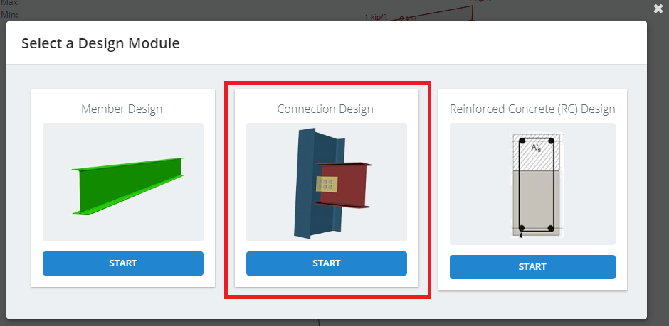
デザインオプションから接続デザインを選択.

select connection design
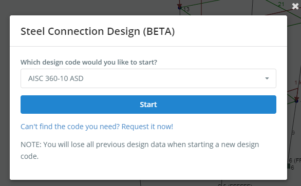
デザイン モジュールを選択し、[開始] をクリックします。.

choose your design module
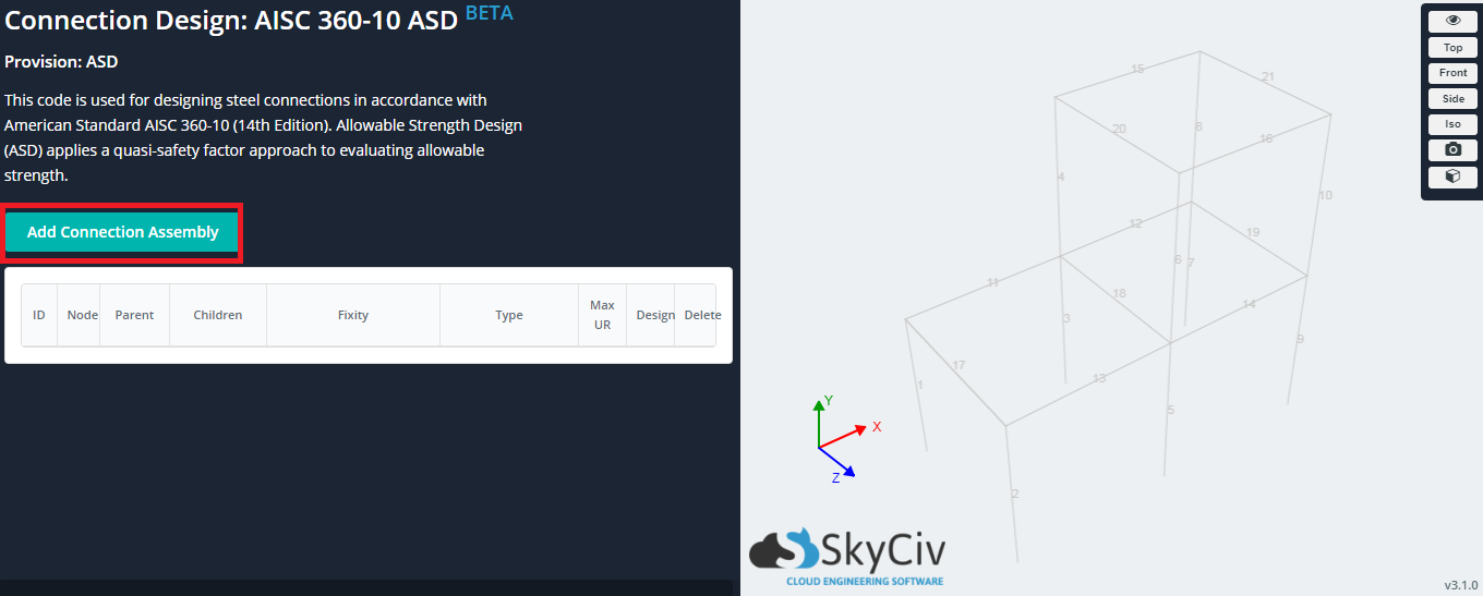
Click the ‘Add Connection Assemblybutton to add a connection.

add connection assembly from button
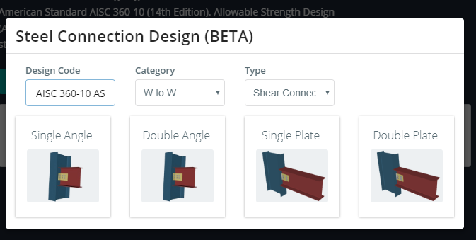
ポップアップから, select a connection to add (タイルをクリック). 「カテゴリ」を変更します’ ドロップダウンと「タイプ’ さまざまなオプションを表示するドロップダウン.

connection pop up options
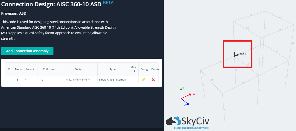
テーブル内の選択した接続で新しい行が作成されます. Proceed to fill in the ‘Parent’ 分野 (this is the supporting member) and the ‘Children’ 分野 (these are the supported members). Certain connections are able to support more than 1 子会員, and you can fill these in with comma separated numbers e.g. 11,12. If a valid selection was made, the ‘Fixityfield will populate with the fixities at the connection location, the ‘Nodefield will populate with the node ID location, and a line representation of the connection will be drawn on the wireframe.

filled in row of connection summary table
To design the connection, click the icon under ‘Design’, and to delete the connection click the icon under ‘Delete’. In the next section we will look at how to edit your connection.

connection summary edit and delete options

スタンドアロン

The standalone version of connection design can be run without having to build a structural model first. This would be useful if the design of the connection and the design of the members are being carried out by different groups in collaboration with one another, しかし独立して.

始めるには, expand the left menu, and click the ‘design’ ボタン. デザインメニューで, click the ‘Connection Design’ モジュール.

start standalone connection design
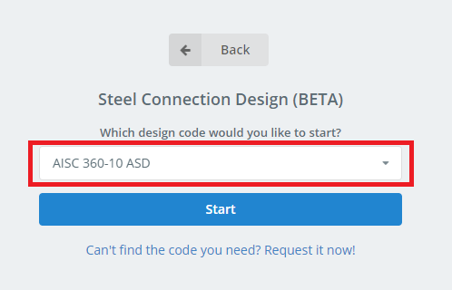
Select the design code applicable for your connection design from the dropdown, and click ‘Start’.

select design code from dropdown
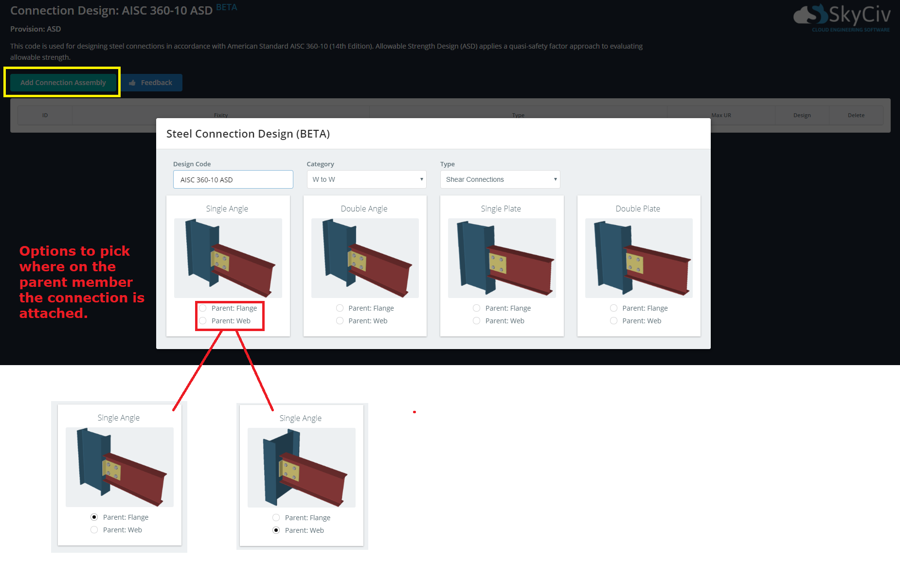
Add a connection by clicking the ‘Add Connection Assemblybutton to bring up a popup of options. Notice that there are some differences in this popup compared to the one that exists in integrated. 最も注目すべきは, there are now radio options to select where on the parent member the connection is attached. This is an important option to make available, 以前から, in the integrated version of connection design, this orientation was determined by the structural model.

standalone version of connection popup options

この記事は役に立ちましたか?
はい 番号

どのように我々は助けることができます?

トップへ戻る