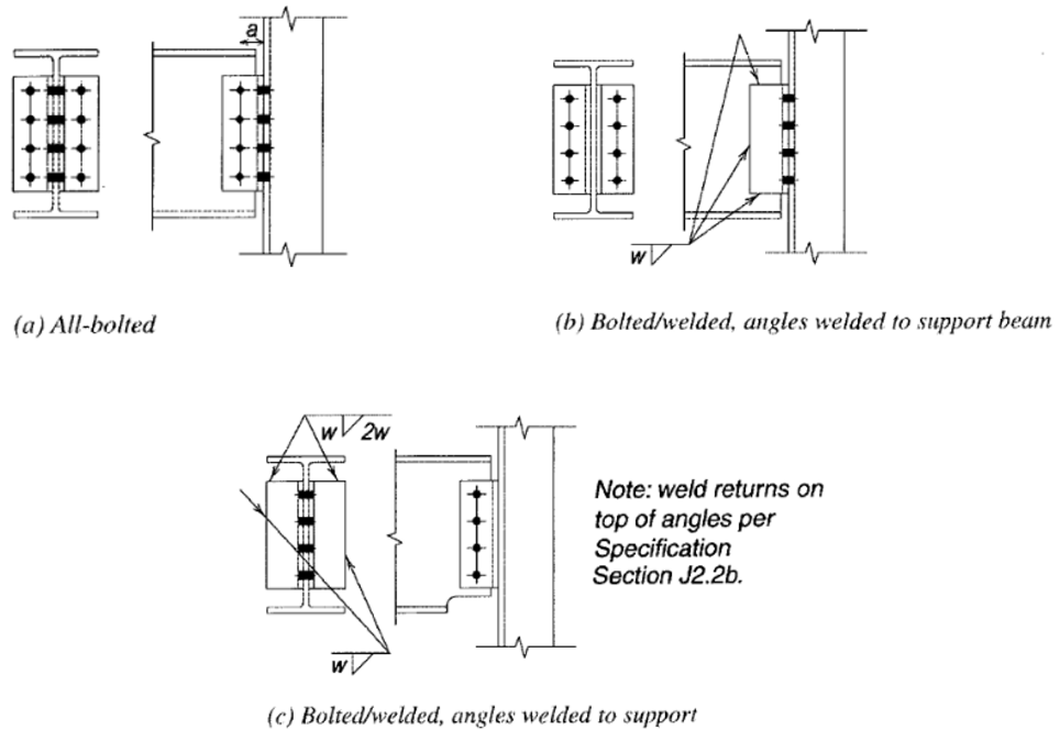
ダブル アングル接続は、一部に示されている 5 つの基本的なせん断接続タイプの 1 つです。 10 の 15第 2 版 AISC マニュアル. この接続タイプは、特に梁と柱のウェブ接続で製作者に好まれています.
ダブル アングルせん断接続は 2 つのアングルで構成されます, 梁ウェブの両側に 1 つずつ. これは、ビーム ウェブまたはサポートにボルト締めまたは溶接することができます。. 通常, 梁と柱のウェブ接続, アングルはビームに溶接され、サポートにボルトで固定されています. この組み合わせでは、脚の角度をやや小さくする必要があります。これは、すべてボルトで固定された接続と比較して、ボルトの取り付けに大きなクリアランスを必要としないため、コラムウェブ内の許容スペースが限られている場合に理想的です。. 梁と桁の構成では、通常、全ボルト締めのダブル アングル接続が推奨されます。特にシングル アングル接続では機能しない場合は、容量が 2 倍になるためです。.
ダブルアングルシャー接続は取り付けが簡単なため好まれています. 基本的なツールと機器を使用して現場で組み立てることができ、特別な製作は必要ありません。. そのため、建設プロジェクトで人気のオプションとなっています.
しかしながら, ダブルアングルせん断接続を設計するには、いくつかの要素に注意する必要があります. AISC は耐荷重を考慮した詳細なガイドラインを提供します, ボルトの間隔, エッジ距離, せん断変形, 曲げ変形を考慮して、さまざまなボルト、角度のサイズ、グレードの許容荷重を決定します。.
ボルト間の間隔は接続のパフォーマンスにとって重要です, ボルトが少なすぎると、ボルトや角度に過度のストレスがかかる可能性があるため, 一方、ボルトが多すぎると不必要にコストがかかり、取り付けが困難になる可能性があります. さらに, アングルとビームフランジエッジの間の距離, 隣接するボルト間の距離も同様です, 材料の過度の応力を防ぎ、適切な荷重伝達を確保するために選択する必要があります.
ダブルアングルせん断接続は、せん断および曲げ変形を経験できます, アングルが回転して耐荷重が低下したり、ボルトやアングルに過度のストレスがかかる可能性があります。. AISC ガイドラインは、これらの変形の影響を計算して制限する式を提供します。.
AISC は、さまざまなビーム タイプおよび荷重条件でのダブル アングル せん断接続の使用に関するガイドラインも提供します。. 例えば, 単純に支持された梁の接続に関するガイドラインは、連続した梁の場合とは異なります。.
ダブルアングルせん断接続は、建設業界で貴重な接続タイプです. しかしながら, 安全で効果的なパフォーマンスを確保するには、上記の要素を慎重に検討する必要があります。. この接続タイプを設計および設置する際には、AISC のガイドラインに従うことが、パフォーマンスを最適化するために不可欠です.
今すぐソフトウェアを使用する.
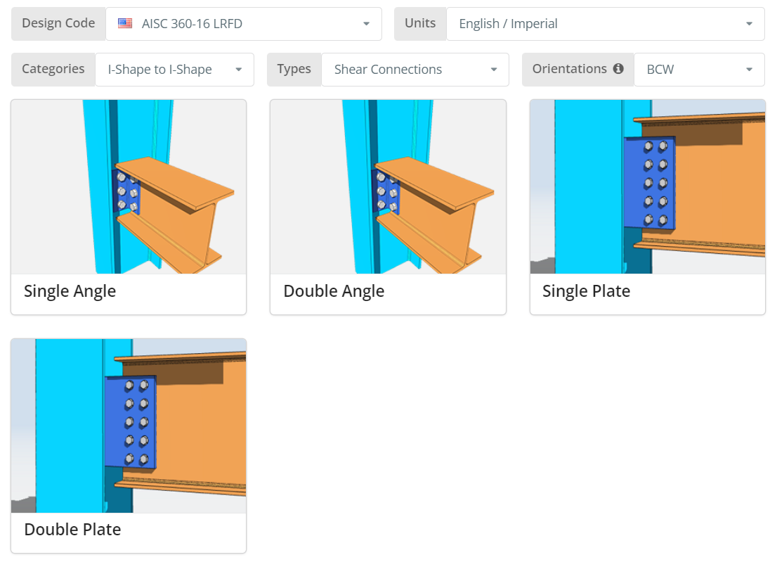
設計コードはAISCにすることができます 360-16 ASDまたはLRFD. 単位はイングリッシュ/インペリアルまたはSI/メトリック. 方向は BCF のいずれかです, BCWまたはBBW. 詳細については、ツールチップにカーソルを合わせてください. 今すぐクリックしてください “ダブルアングル” タイル.
[プロジェクト]タブ
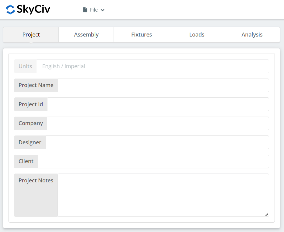
ここでは、現在取り組んでいるプロジェクトの詳細を指定できます.
アセンブリ タブ
[アセンブリ] の下に 3 つのタブがあります. ここで列を指定します, ビーム, と接続 (ダブルアングル) プロパティ.
列タブ
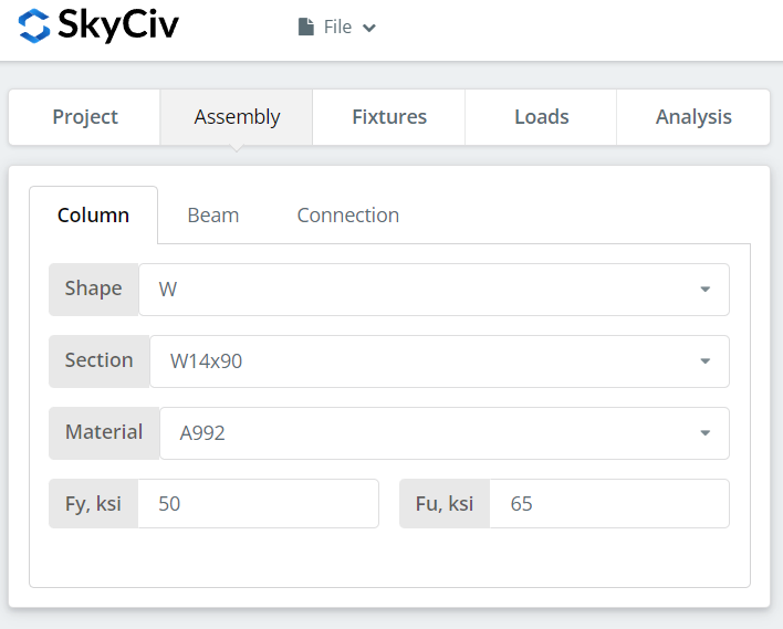
ここでは、柱の断面/形状とその材料グレードを指定できます. A992 または A36 材料を選択できます. でも違う素材を使うなら, [カスタム] を選択して、Fy と Fu の値を手動で入力できます.
梁タブ
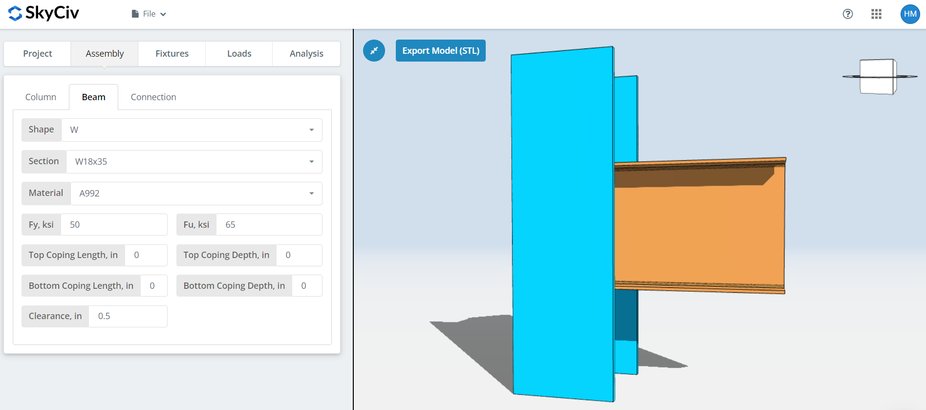
列タブと同様, ここでは、梁の断面/形状と材料グレードを指定できます. 加えて, コープ寸法とビームクリアランスを指定することもできます.
接続タブ
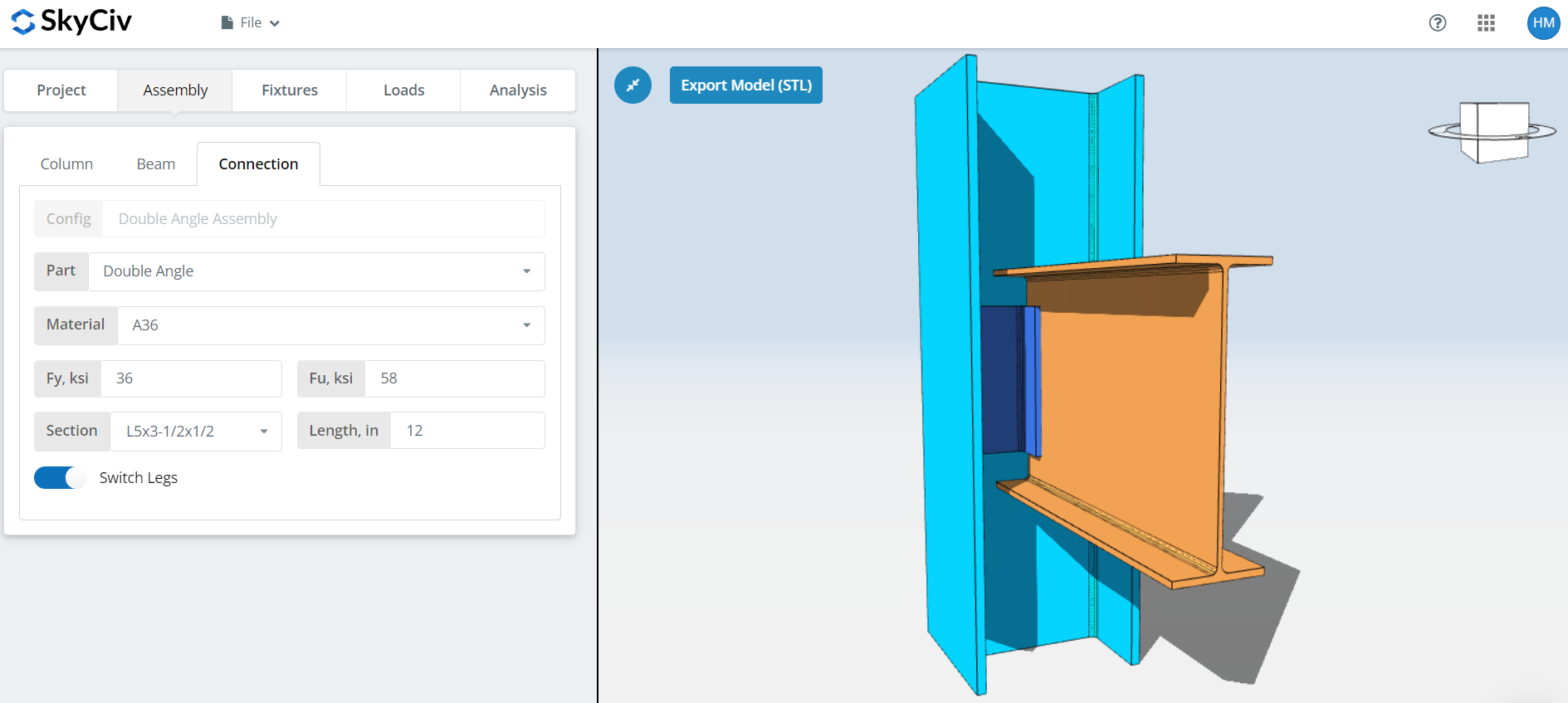
ここでは、倍角のプロパティを指定できます. A36またはA992の材料グレードですが、指定することもできます “カスタム” Fy と Fu を手入力する. セクションのサイズと長さを設定する. 選択した角度サイズの脚のサイズが異なる場合は、脚を切り替えることもできます。. BCWの場合, スペースが非常に限られているため、短い方の脚をコラム側に取り付けるのが理想的です。. ここで、3D レンダラーをよく見て、角度の寸法が適切であることを確認することを忘れないでください。. アングルの高さはビームの深さ内である必要があり、アングルの合計幅は柱の T 寸法または透明なウェブの深さを超えてはなりません.
備品 1 タブ
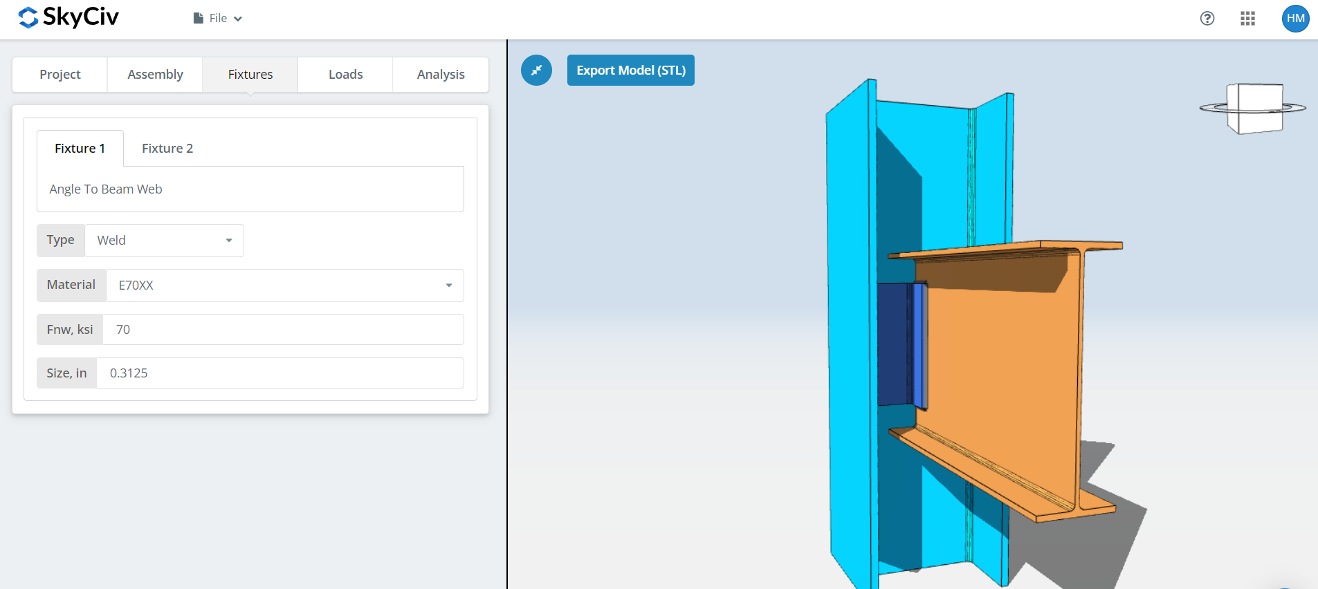
ここでビームウェブ接続の角度を指定できます。. ボルト固定または溶接のいずれかを選択できますが、このデモンストレーションでは, 溶接されたものを選びましょう. 述べたように, BCW用, コラムウェブのスペースが限られているため、溶接/ボルト締めのダブルアングル接続が理想的です。.
最初, 溶接材料を指定してください. 溶接材料のオプションはいくつかありますが、既存の材料が存在しない場合は、, 「カスタム」を使用できます’ そして手動でFnwを入力してください. そして最後に, 溶接サイズを忘れないでください. 溶接サイズがアングルの厚さより大きくないことを確認してください。溶接を完了する余地がなくなるためです。.
備品 2 タブ
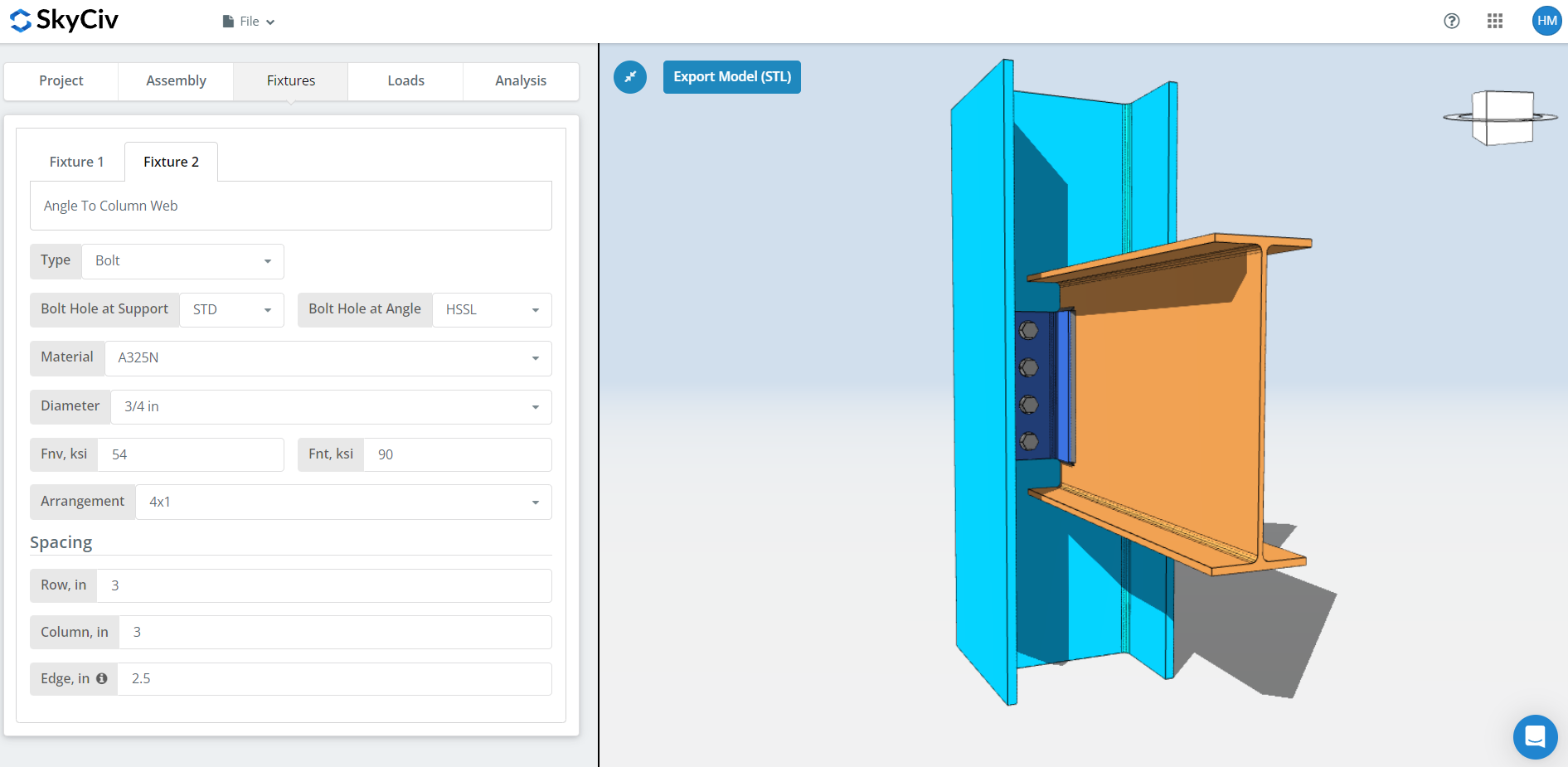
ここでサポートする角度を指定できます (桁ウェブ, 柱フランジ, またはコラムウェブ) 繋がり. ボルト固定または溶接のいずれかを選択できますが、デモンストレーション用です, ここではボルト固定を選択しましょう.
最初, 梁と角度の両方でボルト穴のタイプを指定します. 製造者は通常、標準の穴を使用することを好みます (STD) メンバーおよび水平短溝 (HSSL) 現場でのフィッティングを向上させるために角度を付けた穴.
次, ボルトの材質またはグレードを選択してください. A307のどちらかを選択できます, A325, A490, またはカスタム入力. N対Xに関しては, X はより大きなボルトせん断能力を持っていますが、ボルトのねじ山がせん断面から除外されていることを確認する必要があるため、これをエレクターと適切に伝える必要があります。.
次, ボルトの直径を指定してください. 5/8からお選びいただけます″ 1-1/2まで″ 直径または同等のメートル単位. その後, ボルトの配置を指定してください. まで選択できます 12 行と列をボルトで固定する. ボルトの行と列の間隔も忘れずに指定してください. ここにヒントがあります, より多くのボルト容量が必要な場合は、ボルトの数を増やす代わりに、より大きなボルト間隔を使用できます. プレートの高さが適切で、許容されるビームの深さの範囲内であることを確認してください. 私たちのボルトグループの強みは、 瞬時回転中心法 (ICOR), これは、任意のボルト間隔を指定して、ボルト容量の増加を利用できることを意味します. しかし, 製造業者が可変ボルト間隔に問題がないことを確認する必要があります. 一部の製造業者は 3 を使用することを好みます″ 典型的な間隔. に関しては “縁” 入力, これは、ビームの中心から最も近いボルトまでの水平距離です。.
「荷重」タブ
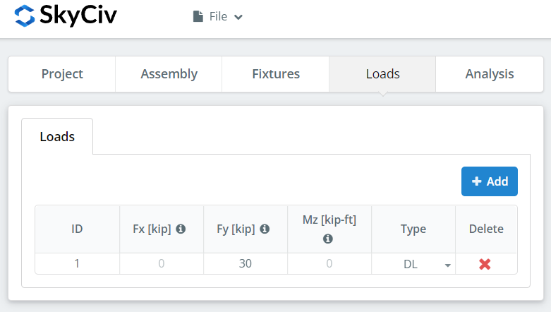
「Fy」に垂直せん断荷重を忘れずに入力してください。.
「分析」タブ
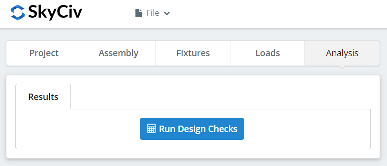
そして最後に, クリック “デザインチェックを実行する”. 前のタブで必要な入力を見逃した場合, これにより、不足している入力を埋めるように通知されます.
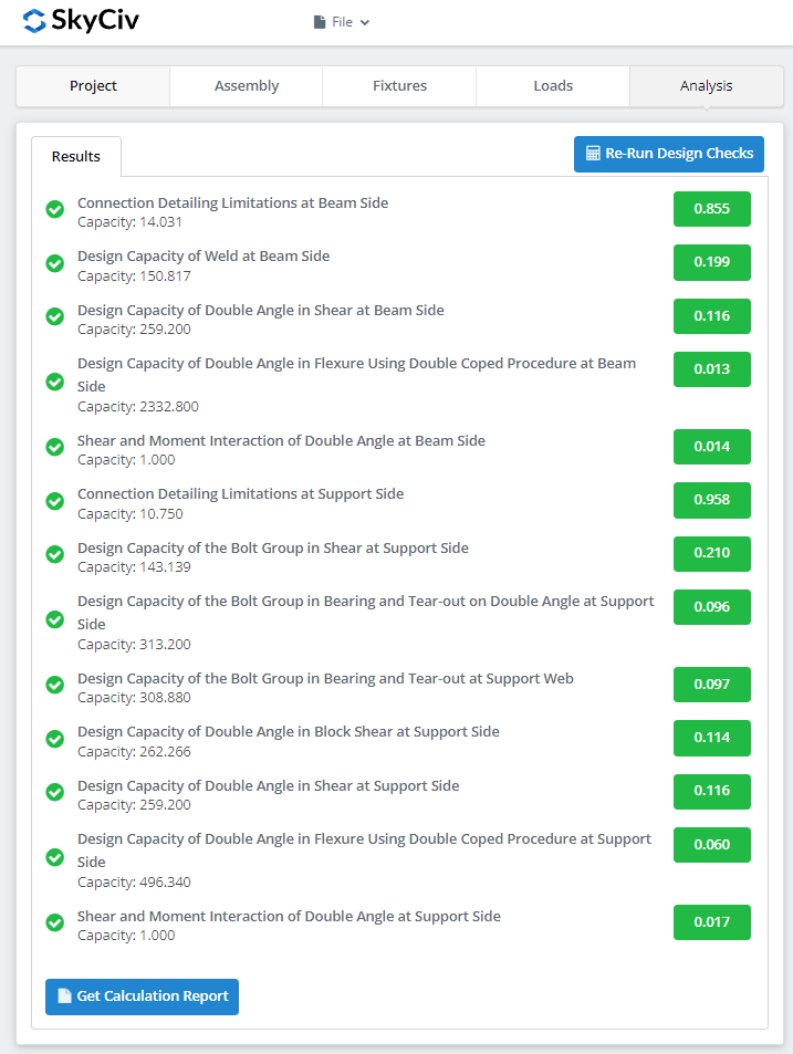
クリックした後 “デザインチェックを実行する”, 接続が失敗したかどうかの概要を確認できます. 失敗した場合, 前のタブの入力を手動で変更してから、, クリック “設計チェックを再実行する”. ようやく大丈夫になったら, クリック “計算レポートの取得” 詳細レポートを見るには.
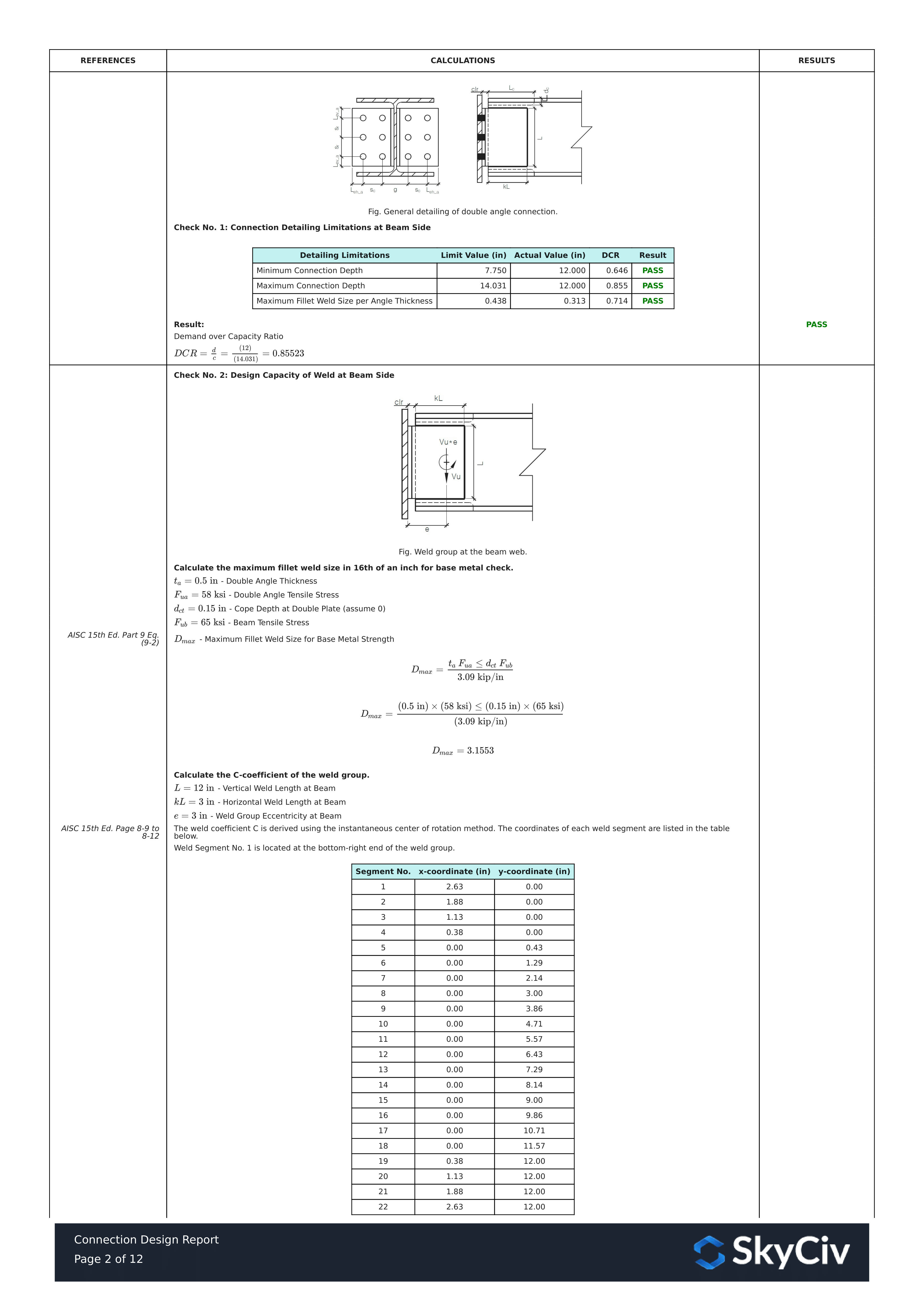
上に表示されているのは、詳細な計算レポートの一部です。. ご覧のように, AISC マニュアルおよび/または仕様への参照がある. これにより、署名エンジニアが計算をクロスチェックしやすくなります。. 私たちの計算は非常に読みやすいです. 説明書に書いてあることと同じように書いてあります, 仕様, またはデザインガイド.
詳細な計算レポート全体の PDF コピーはこちらです… 接続設計レポート. 見てみな!