標準で考慮されるスラブシステム
オーストラリア規格は、鉄筋コンクリート スラブの設計に関する最小要件を定めています。, ワンウェイタイプ、ツーウェイタイプなど. 平面構成と梁の組み方について, スラブは、4 つの側面でサポートされているスラブに分割することもできます, 梁とスラブのシステム, フラットスラブ, と平板. これらのタイプは、次の画像にまとめられています.
SkyCiv の高度な機能によりオーストラリアのスラブ設計コンプライアンスを簡素化 詳細な計算レポートをエクスポートして、成果物または計算パッケージとして使用します. 試してみてください! ASを簡単に適用 3600 スラブと平板のチェック.
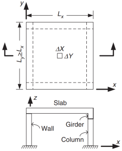
図 1. 四方支持スラブ. (Yew-Chaye Loo & サヌアル・ハグ・チョードリー , “補強およびプレストレストコンクリート”, 2第 2 版, ケンブリッジ大学出版局).
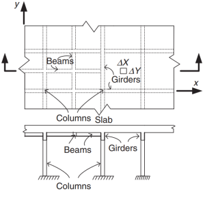
図 2. グリルスラブシステム. (Yew-Chaye Loo & サヌアル・ハグ・チョードリー , “補強およびプレストレストコンクリート”, 2第 2 版, ケンブリッジ大学出版局).
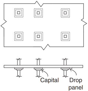
図 3. フラットスラブ. (Yew-Chaye Loo & サヌアル・ハグ・チョードリー , “補強およびプレストレストコンクリート”, 2第 2 版, ケンブリッジ大学出版局).
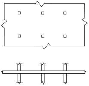
図 4. 平板. (Yew-Chaye Loo & サヌアル・ハグ・チョードリー , “補強およびプレストレストコンクリート”, 2第 2 版, ケンブリッジ大学出版局).
規格はいくつかの方法を推奨しています (シンプルで実証済みの手順) 曲げモーメントの決定:
- 句 6.10.2: 連続梁と一方向スラブ
- 句 6.10.3: 四方支持の二方スラブ
- 句 6.10.4: 複数のスパンを持つ双方向スラブ
コードの目的は、鉄筋の総量をスラブ システムの主な方向に設計することです。. 鉄筋鋼の曲げモーメントが計算されます。 “Mx” そして “私の。” 図 5 コードが抵抗値を規定する有限スラブ要素内の他の力または作用を示します。.
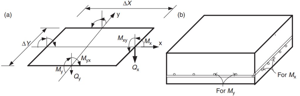
図 5. 有限スラブ要素内の力: 曲げモーメント (Mx, ぼくの), ねじれた瞬間 (ミクシー, ミックス), そしてハサミ (Qx, Qy). (Yew-Chaye Loo & サヌアル・ハグ・チョードリー , “補強およびプレストレストコンクリート”, 2第 2 版, ケンブリッジ大学出版局)
記事上で, 2 つのスラブ設計例を開発します, 一方向および双方向スラブ システム, コード指向で許可されている簡略化されたメソッドを使用する. どちらの場合も, SkyCiv S3D モデルを作成し、結果を上記の方法と比較します。.
あなたがSkyCivで初めての場合, サインアップして自分でソフトウェアをテストする!
一方向スラブの設計例
以下に示すのは、設計する小さな建物とスラブです。
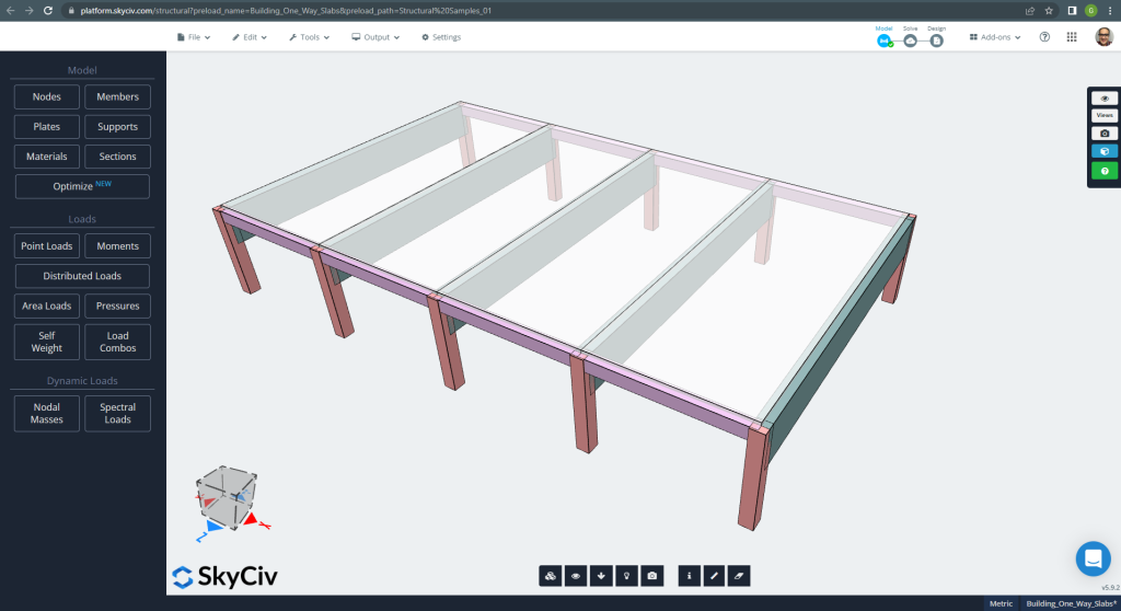
図 6. 小さな建物の一方向スラブの例. (構造3D, SkyCivクラウドエンジニアリング).
平面寸法は次のとおりです。
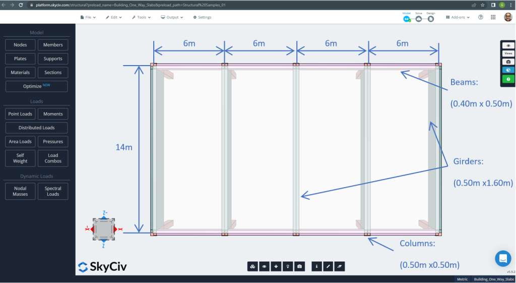
図 7. 平面寸法と構造要素. (構造3D, SkyCivクラウドエンジニアリング).
スラブの例, 要約すれば, 材料, 要素のプロパティ, 考慮すべき負荷 :
- スラブタイプ分類: 1 – 方法行動 \(\フラク{L_2}{L_1} > 2 ; \フラク{14メートル}{6メートル}=2.33 > 2.00 \) OK!
- 建物の占有: 住宅用
- スラブの厚さ \(t_{スラブ}=0.25m\)
- 鉄筋比率を仮定した場合の鉄筋コンクリート密度 0.5% \(\rho_w = 24 \フラク{kN}{m^3} + 0.6 \フラク{kN}{m^3} \回 0.5 = 24.3 \フラク{kN}{m^3} \)
- でのコンクリートの特性圧縮強度 28 日々 \(f'c = 25 MPa \)
- オーストラリア規格によるコンクリートの弾性係数 \(E_c = 26700 MPa \)
- スラブ自重 \(Dead = \rho_w \times t_{スラブ} = 24.3 \フラク{kN}{m^3} \倍 0.25m = 6.075 \フラク {kN}{m^2}\)
- 重畳死荷重 \(SD = 3.0 \フラク {kN}{m^2}\)
- 活荷重 \(L = 2.0 \フラク {kN}{m^2}\)
AS3600規格に準拠した手作業による計算
このセクションで, オーストラリア規格を参考に必要な鉄筋鉄筋を計算いたします。. 最初に、スラブの単一幅のストリップによって実行される合計の要素曲げモーメントを取得します。.
- 死荷重, \(g = (3.0 + 6.075) \フラク{kN}{m^2} \回 1 m = 9.075 \フラク{kN}{メートル}\)
- 活荷重, \(q = (2.0) \フラク{kN}{m^2} \回 1 m = 2.0 \フラク{kN}{メートル}\)
- 究極の負荷, \(Fd = 1.2\times g + 1.5\回 q = (1.2\回 9.075 + 1.5\回 2.0)\フラク{kN}{メートル} =13.89 \frac{kN}{メートル} \)
規格で定められた簡易方式を使用する場合, 最初, 次の制限を遵守する必要があります:
- \(\フラク{L_i}{L_j} \インクルード 1.2 . \フラク{6メートル}{6メートル} =1 < 1.2 \). OK!
- 負荷は均一でなければなりません. OK!
- \(q \le 2g. q=2 \frac{kN}{メートル} < 18.15 \フラク{kN}{メートル}\). OK!
- スラブ断面は均一でなければなりません. OK!.
推奨される最小の厚さ, d
\(d \ge \frac{L_{フェ}}{{k_3}{k_4}{\平方根[3]{\フラク{\フラク{\デルタ}{L_{ef}}{E_c}}{F_{d, ef}}}}}\)
どこ
- \(k_3 = 1.0; k_4 = 1.75 \)
- \(\フラク{\デルタ}{L_{ef}}=1/250 \)
- \(E_c = 27600 MPa \)
- \(F_{d,ef} = (1.0 +k_{cs})\gの倍 + (\psi_s + k_{cs}\times \psi_1) \q=の倍(1.0+0.8)\回 9.075 + (0.7+0.8\回 0.4)\回 2 = 18.375 kPa\)
- \(\psi_s = 0.7 \) 活荷重短期要因
- \(\psi_1 = 0.4 \) 活荷重の長期要因
- \(k_{cs} = 0.8 \)
\(d \ge \frac{5.50メートル}{{1.0}\回 {1.75}{\平方根[3]{\フラク{\フラク{1}{250}\回{27600 \10^3 kPaの倍}}{18.375 kPa}}}} \ゲ 0.173m. d = 0.25m > 0.173メートル \) OK!
制約が満たされていることを証明したら, 曲げモーメントは次の式を使用して計算されます。: \(M=\alpha \times F_d \times L_n^2\) どこ \(\alpha\) は次の図で定義された定数です.
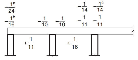
図 8. モーメント係数の値 \(\alpha\) 3 スパンを超えるスラブの場合. (Yew-Chaye Loo & サヌアル・ハグ・チョードリー , “補強およびプレストレストコンクリート”, 2第 2 版, ケンブリッジ大学出版局).
どこ:
- (a) 桁支持上のスラブと梁の場合
- (b) 連続ビームサポートのみの場合
- (c) L級補強材が使用されている場合
- \(L_n \) は単一ストリップ スパンです
- \(F_d \) は重力を考慮した荷重です
スラブの例, ケースを使用する必要があります (a) スラブは硬い桁の上に載っているので、. 1 つのケースのみを説明し、残りは次の表に示します。. 鉄筋面積計算も含まれます.
- \(M={\アルファ} {F_d}{L_n^2}={-\フラク{1}{24}}\回 {13.89 \フラク{kN}{メートル}}\回 (6メートル-0.5メートル)^2 = – 17.51{kN}{メートル}\)
- カバー = 20mm (耐火期間は最低10mm必要です。 60 分).
- \(d = t_{スラブ} – カバー – \フラク{バーの直径}{2} = 250mm – 20んん – 6mm = 224mm \)
- \(\alpha_2 = 1.0-0.003 f’c = 1.0-0.003\times 25 = 0.925 (0.67 \le \alpha_2 \le 0.85) \) したがって, 私たちが選択します \(\alpha_2 = 0.85\)
- \(\xi = \frac{\alpha_2\times f’c}{f_{彼の}} = frac{0.85\回 25 MPa}{500 MPa} = 0.0425 \)
- \(\rho_t = \xi – \平方根{{\xi}^ 2 – \フラク{{2}{\xi}{M}}{{\ファイ}{b}{d^2}{f_{彼の}}}} = 0.0425 – \平方根{{0.0425}^2-\frac{2\times 0.0425\times 17.51{kN}{メートル}}{{0.8}\回 {1メートル}\回 {{(0.224メートル)^ 2}} \回 {500\回 {10他のいくつかの例は}kPa}}}=0.0008814\)
- \(\ガンマ= 1.05-0.007 f’c = 1.05-0.007\times 25 = 0.875 (0.67 \le \gamma \le 0.85) \) したがって, 私たちが選択します \(\ガンマ = 0.85\)
- \(k_u = \frac{\rho_t \times f_{彼の}}{0.85\times \gamma \times f’c}= frac{0.0008814\回 500 MPa}{0.85\回 0.85 \回 25 MPa} =0.0244\)
- \(\ファイ = 1.19 – \フラク{13\k_倍{u0}}{12} = 1.19 – \フラク{13\回 0.0244}{12} = 1.164 (0.6 \le \phi \le 0.8) \) したがって, 私たちが選択します \(\ファイ = 0.8\). OK!.
- \(\曲げモーメントは、セクションで各方向に計算されます{t,分} = 0.20 {(\フラク{D}{d})^ 2}{(\フラク{f’_{ct,f}}{f_{彼の}})} = 0.20 \回 (\フラク{0.25メートル}{0.224メートル})^2 \times \frac{0.6\回 sqrt{25MPa}}{500 MPa} = 0.0015\)
- \(A_{st}=最大(\曲げモーメントは、セクションで各方向に計算されます{t,分}, \rho_t)\times b \times d = max(0.0015,0.0008814)\回 1000 mm \times 224 mm = 334.82 mm^2 \)
| \(\alpha\) そして瞬間 | エクステリア ネガティブ 左 | エクステリアポジティブ | 外側の負の右 | 内側の負の左 | インテリアポジティブ | 内側の負の右 |
|---|---|---|---|---|---|---|
| \(\alpha\) 値 | -\(\フラク{1}{24}\) | \(\フラク{1}{11}\) | -\(\フラク{1}{10}\) | \(\フラク{1}{10}\) | \(\フラク{1}{16}\) | \(\フラク{1}{11}\) |
| M値 | -17.51 | 38.20 | -42.02 | 42.02 | 26.26 | 38.20 |
| \(\rho_t\) | 0.0008814 | 0.001948 | 0.002148 | 0.002148 | 0.00133 | 0.001948 |
| に | 0.0244 | 0.0539 | 0.0594 | 0.0594 | 0.0368 | 0.05391 |
| \(\ファイ) | 0.8 | 0.8 | 0.8 | 0.8 | 0.8 | 0.8 |
| \(A_{st} {mm^2}\) | 334.82 | 436.31 | 481.099 | 481.099 | 334.8214 | 436.3100 |
鉄筋面積計算後, 詳細を定義できます (スラブに鉄筋を配置する実際の方法). 知るための助けとして, 次の画像を共有します, 正および負のモーメントの鉄筋の位置を示します:
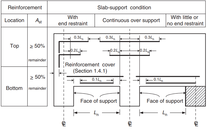
図 9. 一方向および双方向スラブの配筋. (Yew-Chaye Loo & サヌアル・ハグ・チョードリー , “補強およびプレストレストコンクリート”, 2第 2 版, ケンブリッジ大学出版局)
あなたがSkyCivで初めての場合, サインアップして自分でソフトウェアをテストする!
SkyCiv S3D プレート デザイン モジュールの結果
最初のビューでは, S3D での例のモデリングと構造解析のためのいくつかの画像を示します. SkyCiv でのモデリングについては、次のリンクを参照することをお勧めします。 プレートのモデリング方法? そして SkyCiv を使用した ACI スラブ設計例.
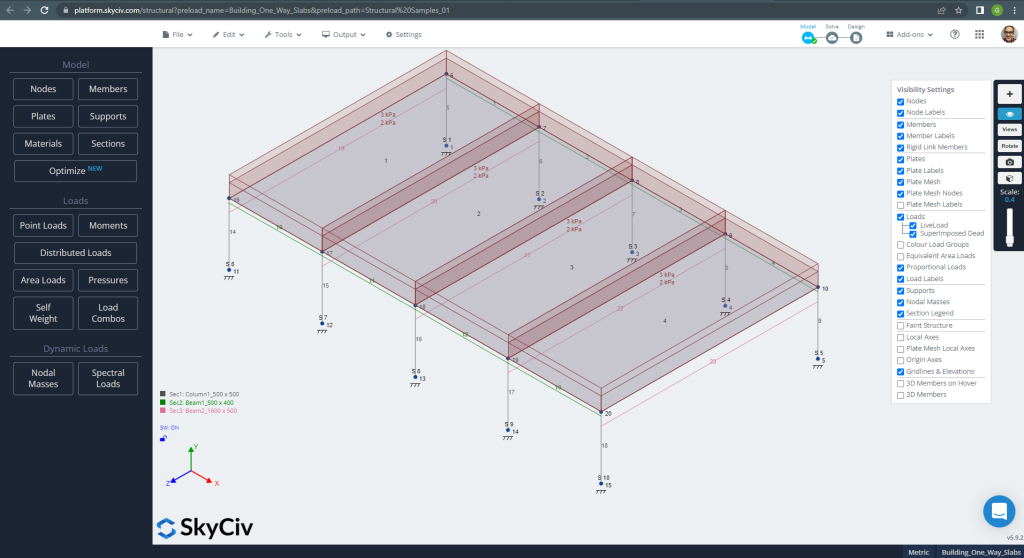
図 10. 一方向スラブの S3D 構造モデルの例. (構造3D, SkyCivクラウドエンジニアリング).
モデルを分析する前に, プレート メッシュ サイズを定義する必要があります. 参考文献 (2) のシェル要素のサイズを推奨します 1/6 短いスパンのまたは 1/8 ロングスパンの, それらの短い方. この値に従う, 我々は持っています \(\フラク{L2}{6}= frac{6メートル}{6} = 1メートル \) または \(\フラク{L1}{8}= frac{14メートル}{8}=1.75m \); 最大推奨サイズとして 1m を採用し、適用メッシュ サイズは 0.50m です。.
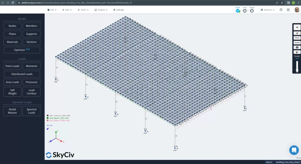
図 11. プレートのメッシュの改良. (構造3D, SkyCivクラウドエンジニアリング).
解析構造モデルを改善したら, 線形弾性解析を実行します. スラブを設計するとき, 垂直変位がコードで許可されている最大値よりも小さいかどうかを確認する必要があります. オーストラリアのスタンダードは、最大整備可能垂直変位を確立しました。 \(\フラク{L}{250}= frac{6000んん}{250}=24.0 mm\).
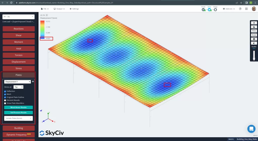
図 12. プレートの垂直変位. (構造3D, SkyCivクラウドエンジニアリング).
最大垂直変位とコード参照値の比較, スラブの剛性は十分です. \(4.822 んん < 24.00mm\).
スラブのスパンの最大モーメントは、正の場合は中心に、負の場合は外側と内側のサポートにあります。. 次の画像でこれらのモーメントの値を見てみましょう.
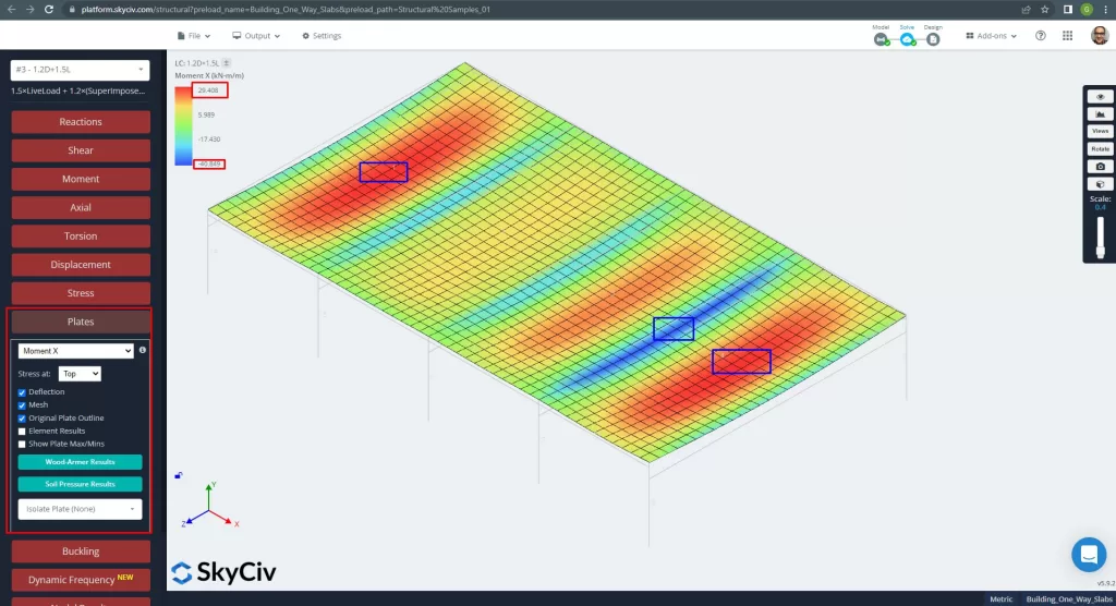
図 13. X方向のモーメント. (構造3D, SkyCivクラウドエンジニアリング).
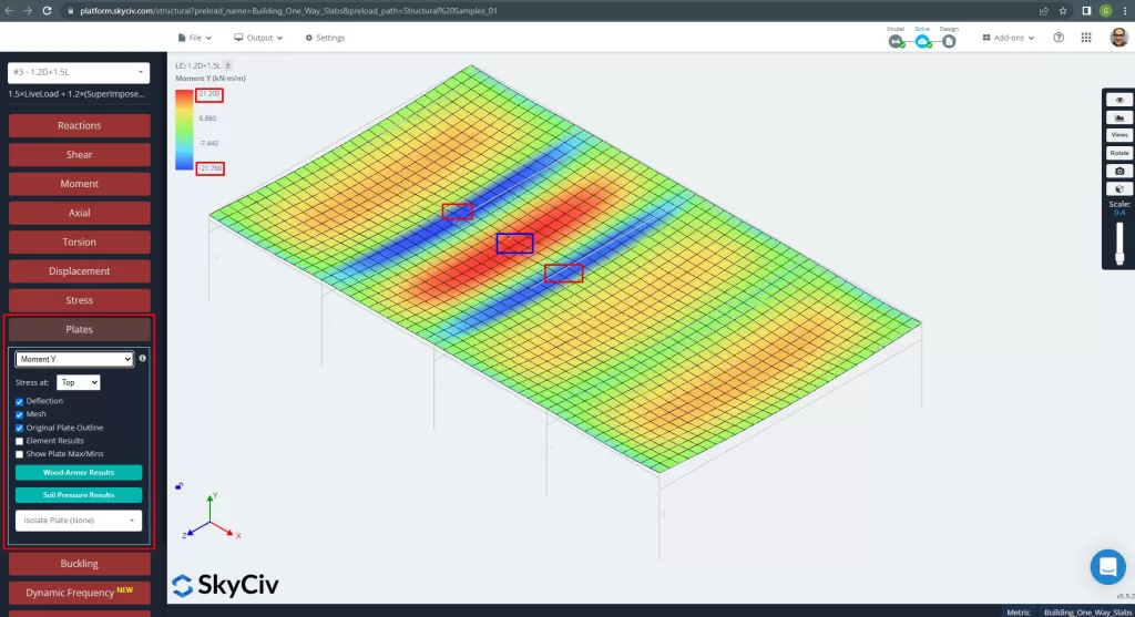
図 14. Y方向のモーメント. (構造3D, SkyCivクラウドエンジニアリング).
プレート要素のローカル軸を以下に示します。.
図 15. スラブローカル軸. (構造3D, SkyCivクラウドエンジニアリング).
自動強化スラブ設計の詳細については、こちらをご覧ください。, ドキュメントを参照してください SkyCiv のプレート.
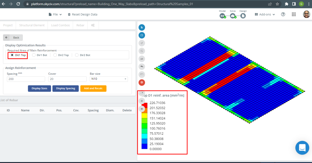
図 16. トップD1補強. (構造3D, SkyCivクラウドエンジニアリング).
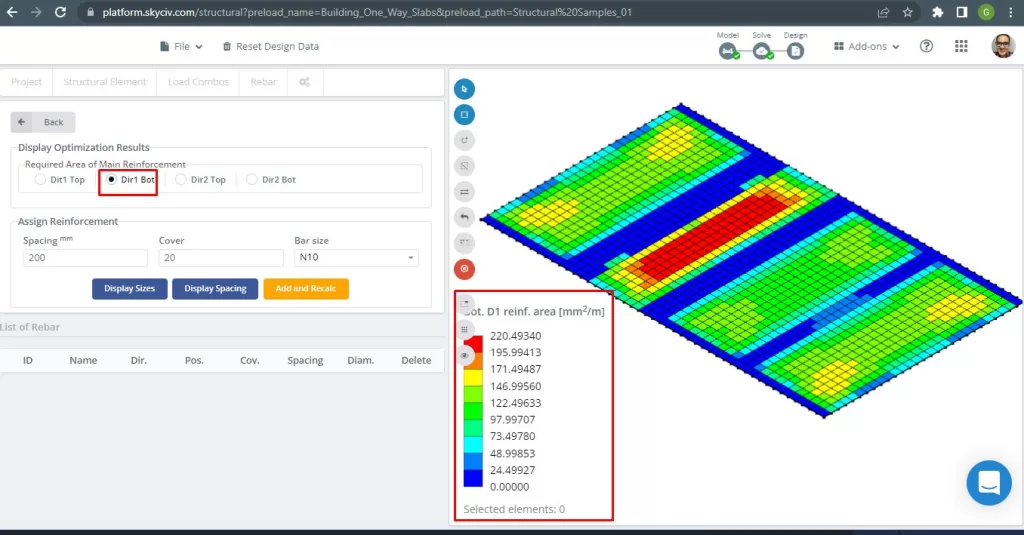
図 17. 底部D1補強. (構造3D, SkyCivクラウドエンジニアリング).
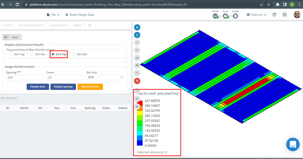
図 18. 上部 D2 補強. (構造3D, SkyCivクラウドエンジニアリング).
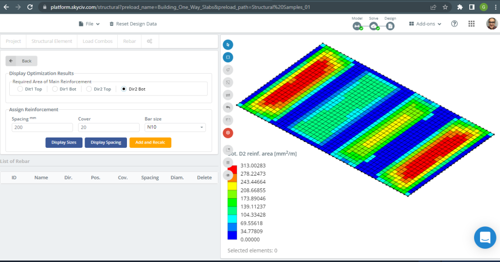
図 19. 底部D2補強. (構造3D, SkyCivクラウドエンジニアリング).
結果比較
この一方向スラブ設計例の最後のステップは、S3D 解析によって得られた鉄筋面積を比較することです。 (ローカル軸 “2”) と手計算.
| モーメントと鋼材エリア | エクステリア ネガティブ 左 | エクステリアポジティブ | 外側の負の右 | 内側の負の左 | インテリアポジティブ | 内側の負の右 |
|---|---|---|---|---|---|---|
| \(A_{st, 手計算} {mm^2}\) | 334.82 | 436.31 | 481.099 | 481.099 | 334.8214 | 436.3100 |
| \(A_{st, S3D} {mm^2}\) | 285.13 | 313.00 | 427.69 | 427.69 | 313.00 | 427.69 |
| \(\デルタ_{差分}\) (%) | 14.84 | 28.262 | 11.101 | 11.101 | 6.517 | 1.986 |
値の結果が互いに非常に近いことがわかります. これは、計算が正しいことを意味します!
双方向スラブの設計例
このセクションで, グリルシステムで構成される例を開発します.
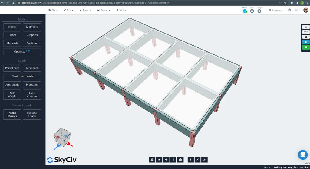
図 20. グリルシステム. (構造3D, SkyCivクラウドエンジニアリング).
平面寸法は次のとおりです。
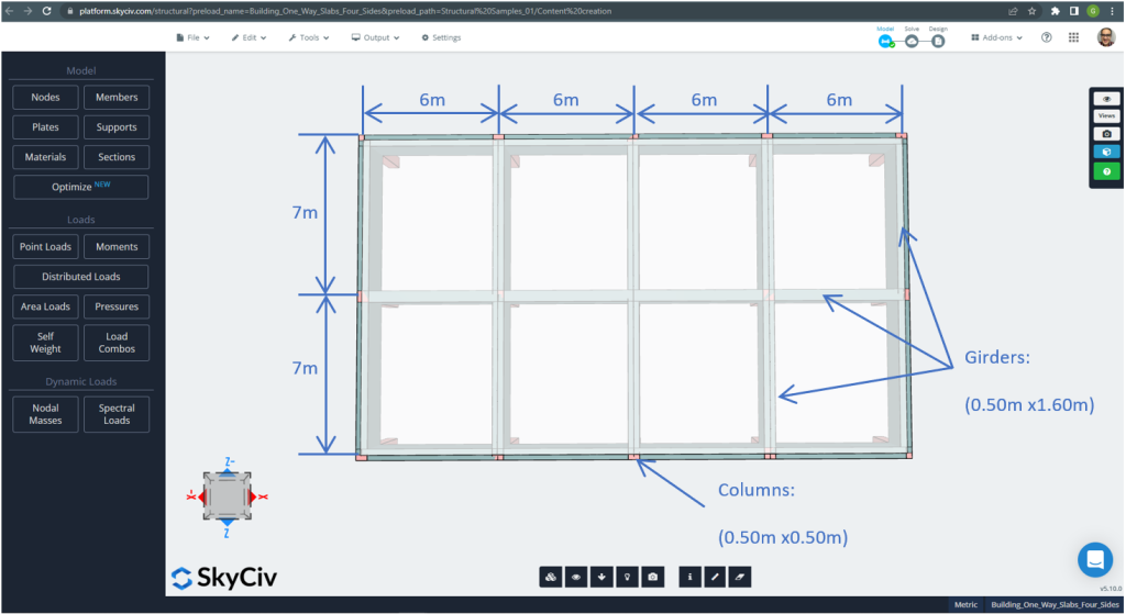
図 21. 4面二方スラブ例の平面寸法. (構造3D, SkyCivクラウドエンジニアリング).
スラブの例, 要約すれば, 材料, 要素のプロパティ, 考慮すべき負荷 :
- スラブタイプ分類: 二 – 方法行動 \(\フラク{L_2}{L_1} \インクルード 2 ; \フラク{7メートル}{6メートル}=1.167 < 2.00 \) OK!
- 建物の占有: 住宅用
- スラブの厚さ \(t_{スラブ}=0.25m\)
- 鉄筋比率を仮定した場合の鉄筋コンクリート密度 0.5% \(\rho_w = 24 \フラク{kN}{m^3} + 0.6 \フラク{kN}{m^3} \回 0.5 = 24.3 \フラク{kN}{m^3} \)
- でのコンクリートの特性圧縮強度 28 日々 \(f'c = 25 MPa \)
- オーストラリア規格によるコンクリートの弾性係数 \(E_c = 26700 MPa \)
- スラブ自重 \(Dead = \rho_w \times t_{スラブ} = 24.3 \フラク{kN}{m^3} \倍 0.25m = 6.075 \フラク {kN}{m^2}\)
- 重畳死荷重 \(SD = 3.0 \フラク {kN}{m^2}\)
- 活荷重 \(L = 2.0 \フラク {kN}{m^2}\)
AS3600規格に準拠した手作業による計算
このセクションで, オーストラリア規格を参考に必要な鉄筋鉄筋を計算いたします。. まず、各主曲げ方向でスラブの単一幅ストリップによって実行される合計係数曲げモーメントを取得します。.
- 死荷重, \(g = (3.0 + 6.075) \フラク{kN}{m^2} \回 1 m = 9.075 \フラク{kN}{メートル}\)
- 活荷重, \(q = (2.0) \フラク{kN}{m^2} \回 1 m = 2.0 \フラク{kN}{メートル}\)
- 究極の負荷, \(Fd = 1.2\times g + 1.5\回 q = (1.2\回 9.075 + 1.5\回 2.0)\フラク{kN}{メートル} =13.89 \frac{kN}{メートル} \)
設計モーメントと係数
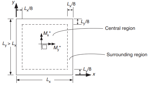
図 22. 正のモーメントを決定するための 2 方向スラブの方向. (Yew-Chaye Loo & サヌアル・ハグ・チョードリー , “補強およびプレストレストコンクリート”, 2第 2 版, ケンブリッジ大学出版局)
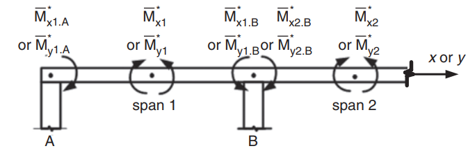
図 23. 双方向スラブにおける負のモーメントの決定. (Yew-Chaye Loo & サヌアル・ハグ・チョードリー , “補強およびプレストレストコンクリート”, 2第 2 版, ケンブリッジ大学出版局)
| エッジ状態 | ショートスパン係数 (\(\beta_x\)) | ロングスパン係数 (\(\ベータ_y)\) のすべての値 \(\フラク{L_y}{L_x}\) | |||||||
|---|---|---|---|---|---|---|---|---|---|
| の値 \(\フラク{L_y}{L_x}\) | |||||||||
| 1.0 | 1.1 | 1.2 | 1.3 | 1.4 | 1.5 | 1.75 | \(\の場合、ベースの下部から壁の高さの半分 2.0\) | ||
| 1. 4つのエッジが連続 | 0.024 | 0.028 | 0.032 | 0.035 | 0.037 | 0.040 | 0.044 | 0.048 | 0.024 |
| 2. 1 つの短辺の不連続部 | 0.028 | 0.032 | 0.036 | 0.038 | 0.041 | 0.043 | 0.047 | 0.050 | 0.028 |
| 3. 1 つの長いエッジが不連続 | 0.028 | 0.035 | 0.041 | 0.046 | 0.050 | 0.054 | 0.061 | 0.066 | 0.028 |
| 4. 2 つの短辺が不連続 | 0.034 | 0.038 | 0.040 | 0.043 | 0.045 | 0.047 | 0.050 | 0.053 | 0.034 |
| 5. 2 つの長いエッジが不連続 | 0.034 | 0.046 | 0.056 | 0.065 | 0.072 | 0.078 | 0.091 | 0.100 | 0.034 |
| 6. 2 つの隣接するエッジが不連続である | 0.035 | 0.041 | 0.046 | 0.051 | 0.055 | 0.058 | 0.065 | 0.070 | 0.035 |
| 7. 3 つのエッジが不連続 (連続した 1 つの長いエッジ) | 0.043 | 0.049 | 0.053 | 0.057 | 0.061 | 0.064 | 0.069 | 0.074 | 0.043 |
| 8. 3 つのエッジが不連続 (1 つの短いエッジが連続している) | 0.043 | 0.054 | 0.064 | 0.072 | 0.078 | 0.084 | 0.096 | 0.105 | 0.043 |
| 9. 4 つのエッジが不連続である | 0.056 | 0.066 | 0.074 | 0.081 | 0.087 | 0.093 | 0.103 | 0.111 | 0.056 |
テーブル 1. (Yew-Chaye Loo & サヌアル・ハグ・チョードリー , “補強およびプレストレストコンクリート”, 2第 2 版, ケンブリッジ大学出版局)
次の図は、上の表で参照されている 9 つのケースすべてを説明しています。
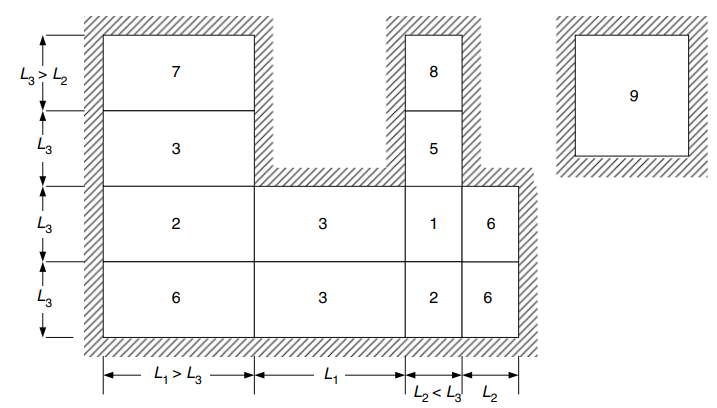
図 24. 4 つの側面でサポートされる 2 方向スラブのエッジ条件. (Yew-Chaye Loo & サヌアル・ハグ・チョードリー , “補強およびプレストレストコンクリート”, 2第 2 版, ケンブリッジ大学出版局)
中部地域のデザインモーメント (場合 6 2 つの隣接するエッジが不連続である) :
- \(L_x = 6m, L_y=7m, \フラク{L_y}{L_x} = frac{7メートル}{6メートル}= 1.167 \) 線形補間する値
- ポジティブ:
- \(M_x = {\ベータ_x}{F_d}{L_x^2} = {0.04435}\回 {13.89 \フラク{kN}{メートル}}\回{(6メートル)^ 2}=22.177 kNm\)
- \(M_y = {\ベータ_y}{F_d}{L_x^2} ={0.035}\回 {13.89 \フラク{kN}{メートル}}\回{(6メートル)^ 2}=17.501kNm \)
- 負の外部スパン:
- \(M_{×1、A} = -\lambda_e \times M_x = -0.5 \回 22.177 kNm = – 11.089 kNm\)
- \(M_{y1,A} = -\lambda_e \times M_y = -0.5 \回 17.501 kNm = -8.751 kNm \)
- 負の内部スパン:
- \(M_{×1、B} = -\lambda_{1バツ} \M_x 倍 = -1.33 \回 22.177 kNm = – 29.495 kNm\)
- \(M_{y1, B} = -\lambda_{1そして} \M_y の倍 = -1.33 \回 17.501 kNm = -23.276 kNm \)
中部地域のデザインモーメント (場合 3 1 つの長いエッジが不連続) :
- \(L_x = 6m, L_y=7m, \フラク{L_y}{L_x} = frac{7メートル}{6メートル}= 1.167 \) 線形補間する値
- ポジティブ:
- \(M_x = {\ベータ_x}{F_d}{L_x^2} = {0.03902}\回 {13.89 \フラク{kN}{メートル}}\回{(6メートル)^ 2}= 19.512 kNm\)
- \(M_y = {\ベータ_y}{F_d}{L_x^2} ={0.028}\回 {13.89 \フラク{kN}{メートル}}\回{(6メートル)^ 2}= 14.001 kNm \)
- 負の内部スパン:
- \(M_{×1、B} = -\lambda_{1バツ} \M_x 倍 = -1.33 \回 19.512 kNm = – 25.951 kNm\)
- \(M_{y1、B} = -\lambda_{1そして} \M_y の倍 = -1.33 \回 14.001 kNm = – 18.621 kNm \)
- ネガティブ内部の第 2 スパン:
- \(M_{×2、B} = -\lambda_{2バツ} \M_x 倍 = -1.33 \回 19.512 kNm = – 25.951 kNm\)
- \(M_{y2,B} = -\lambda_{2そして} \M_y の倍 = -1.33 \回 14.001 kNm = – 18.621 kNm \)
X方向用鉄筋鋼
| \(\alpha\) そして瞬間 | エクステリア ネガティブ 左 | エクステリアポジティブ | 外側の負の右 | 内側の負の左 | インテリアポジティブ | 内側の負の右 |
|---|---|---|---|---|---|---|
| M値 | 11.089 | 22.177 | 29.495 | 25.951 | 19.512 | 25.951 |
| \(\rho_t\) | 0.00055614 | 0.00112 | 0.001496 | 0.001313 | 0.000984 | 0.001313 |
| に | 0.015395 | 0.0310 | 0.0414 | 0.0364 | 0.0272 | 0.0364 |
| \(\ファイ) | 0.8 | 0.8 | 0.8 | 0.8 | 0.8 | 0.8 |
| \(A_{st} {mm^2}\) | 334.8214 | 334.8214 | 335.08233 | 334.821 | 334.8214 | 334.8214 |
Y方向用鉄筋鋼
| \(\alpha\) そして瞬間 | エクステリア ネガティブ 左 | エクステリアポジティブ | 外側の負の右 | 内側の負の左 | インテリアポジティブ | 内側の負の右 |
|---|---|---|---|---|---|---|
| M値 | 8.751 | 17.501 | 23.276 | 18.621 | 14.001 | 18.621 |
| \(\rho_t\) | 0.0004383 | 0.0008811 | 0.001176 | 0.0009381 | 0.000703 | 0.0009381 |
| に | 0.0121 | 0.0244 | 0.03256 | 0.02597 | 0.0195 | 0.02597 |
| \(\ファイ) | 0.8 | 0.8 | 0.8 | 0.8 | 0.8 | 0.8 |
| \(A_{st} {mm^2}\) | 334.821 | 334.821 | 334.821 | 334.821 | 334.8214 | 334.821 |
あなたがSkyCivで初めての場合, サインアップして自分でソフトウェアをテストする!
SkyCiv S3D プレート デザイン モジュールの結果
モデルを改良した後, 線形弾性解析を実行しましょう.
スラブを設計するとき, 垂直変位がコードで許可されている最大値よりも小さいかどうかを確認する必要があります. オーストラリアのスタンダードは、最大整備可能垂直変位を確立しました。 \(\フラク{L}{250}= frac{6000んん}{250}=24.0 mm\).
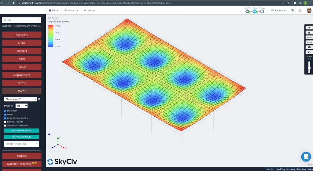
図 25. グリルスラブシステムの垂直変位. (構造3D, SkyCivクラウドエンジニアリング).
上の画像は、垂直方向の変位を示しています. 最大値は -1.179mm で、許容最大値 -24mm より小さくなります。. したがって, スラブの剛性は十分です.
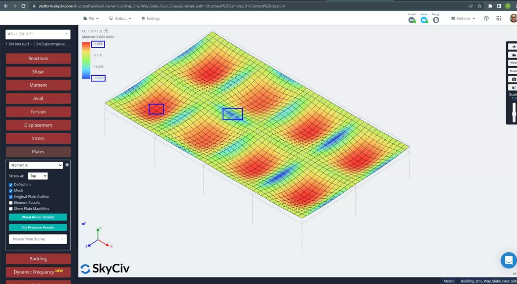
図 26. X方向のプレートモーメント. (構造3D, SkyCivクラウドエンジニアリング).
画像 27 そして 28 各主方向の曲げモーメントからなる. モーメント分布と値を取る, ソフトウェア, SkyCiv, 次に、鉄筋の総面積を取得できます.
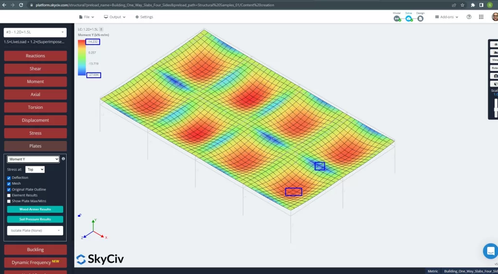
図 27. Y方向のプレートモーメント. (構造3D, SkyCivクラウドエンジニアリング).
鋼補強エリア:
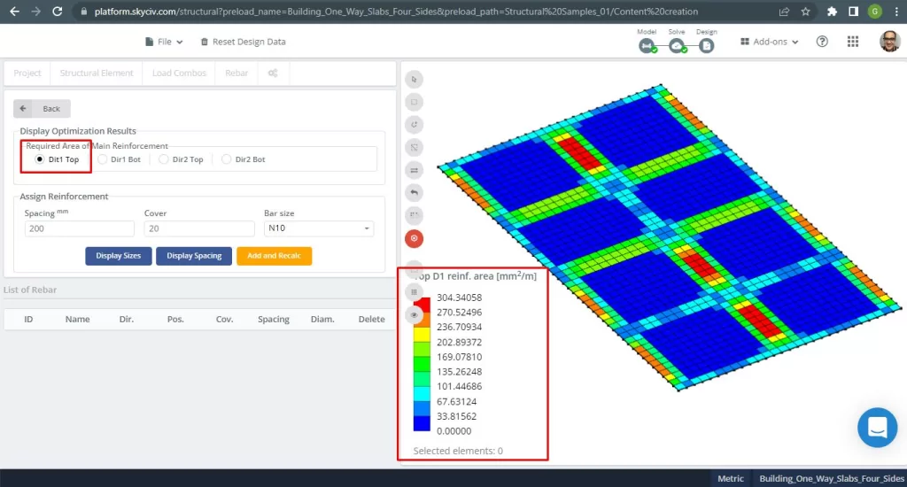
図 28. 上部の鉄筋の方向の補強 1. (構造3D, SkyCivクラウドエンジニアリング).
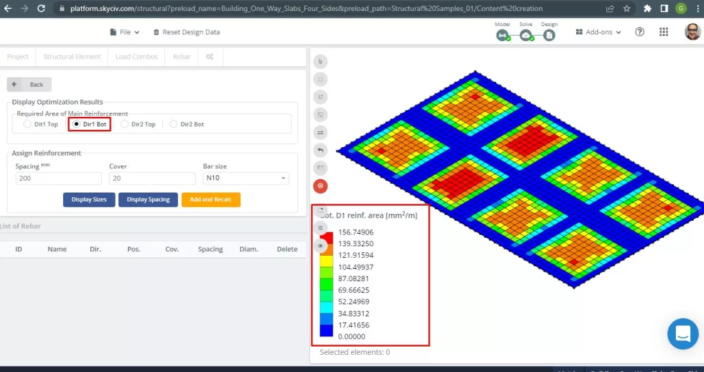
図 29. 下部鋼鉄筋の方向の補強 1. (構造3D, SkyCivクラウドエンジニアリング).
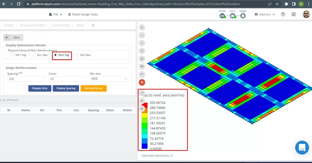
図 30. 上部の鉄筋の方向の補強 2. (構造3D, SkyCivクラウドエンジニアリング).
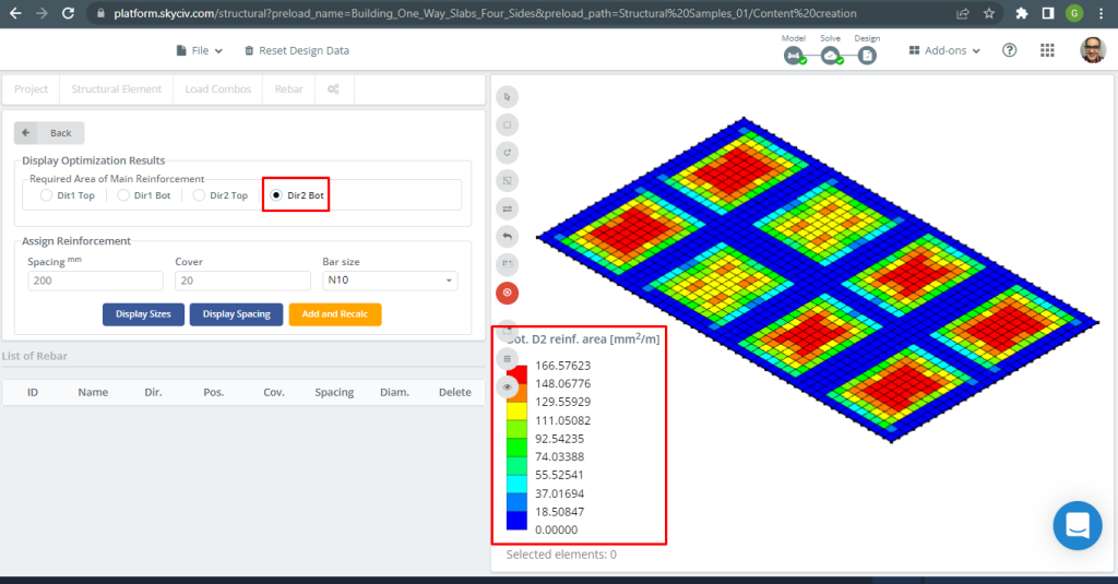
図 31. 下部鋼鉄筋の方向の補強 2. (構造3D, SkyCivクラウドエンジニアリング).
結果比較
この一方向スラブ設計例の最後のステップは、S3D 解析と手計算によって得られた鉄筋面積を比較することです。.
X方向用鉄筋鋼
| モーメントと鋼材エリア | エクステリア ネガティブ 左 | エクステリアポジティブ | 外側の負の右 | 内側の負の左 | インテリアポジティブ | 内側の負の右 |
|---|---|---|---|---|---|---|
| \(A_{st, 手計算} {mm^2}\) | 334.8214 | 334.8214 | 335.08233 | 334.821 | 334.8214 | 334.8214 |
| \(A_{st, S3D} {mm^2}\) | 289.75 | 149.35 | 325.967 | 325.967 | 116.16 | 217.311 |
| \(\デルタ_{差分}\) (%) | 13.461 | 55.39 | 2.720 | 2.644 | 65.307 | 35.0964 |
Y方向用鉄筋鋼
| モーメントと鋼材エリア | エクステリア ネガティブ 左 | エクステリアポジティブ | 外側の負の右 | 内側の負の左 | インテリアポジティブ | 内側の負の右 |
|---|---|---|---|---|---|---|
| \(A_{st, 手計算} {mm^2}\) | 334.821 | 334.821 | 334.821 | 334.821 | 334.821 | 334.821 |
| \(A_{st, S3D} {mm^2}\) | 270.524 | 156.75 | 304.34 | 304.34 | 156.75 | 270.52 |
| \(\デルタ_{差分}\) (%) | 19.203 | 53.184 | 9.104 | 9.104 | 53.184 | 19.204 |
正のモーメントでは差が若干大きくなります。その理由は、プレート有限要素解析結果と曲げ鉄筋の計算に影響を与える高いねじり剛性を持つ梁の存在であると考えられます。.
あなたがSkyCivで初めての場合, サインアップして自分でソフトウェアをテストする!
参考文献
- Yew-Chaye Loo & サヌアル・ハグ・チョードリー , “補強およびプレストレストコンクリート”, 2第 2 版, ケンブリッジ大学出版局.
- バザン・エンリケ & メリ・ピラーラ, “構造物の耐震設計”, 1ed, クリア.
- オーストラリア規格, コンクリート構造物, なので 3600:2018