擁壁の設計
コンクリート擁壁設計を実行するプロセスは、3 つの主要な段階で構成されます。:
- 事前の寸法記入: 推奨される比率を使用して、各コンポーネントのベースライン寸法を設定します。.
- 安定性チェック: 壁が受ける荷重条件下で壁の形状が安定していることを確認してください。. 基本的に横土圧と付加荷重.
- 設計: 材料特性と計算された内部作用について (せん断と曲げ) 設計コードに従って壁が抵抗要件を満たしていることを確認してください.
記事上で, 擁壁を適切に設計するための各ステップの説明に焦点を当てます。. SkyCiv ソフトウェアでどのように適用されるかを学ぶには, に関する記事をご覧ください 擁壁設計例.
事前の寸法記入
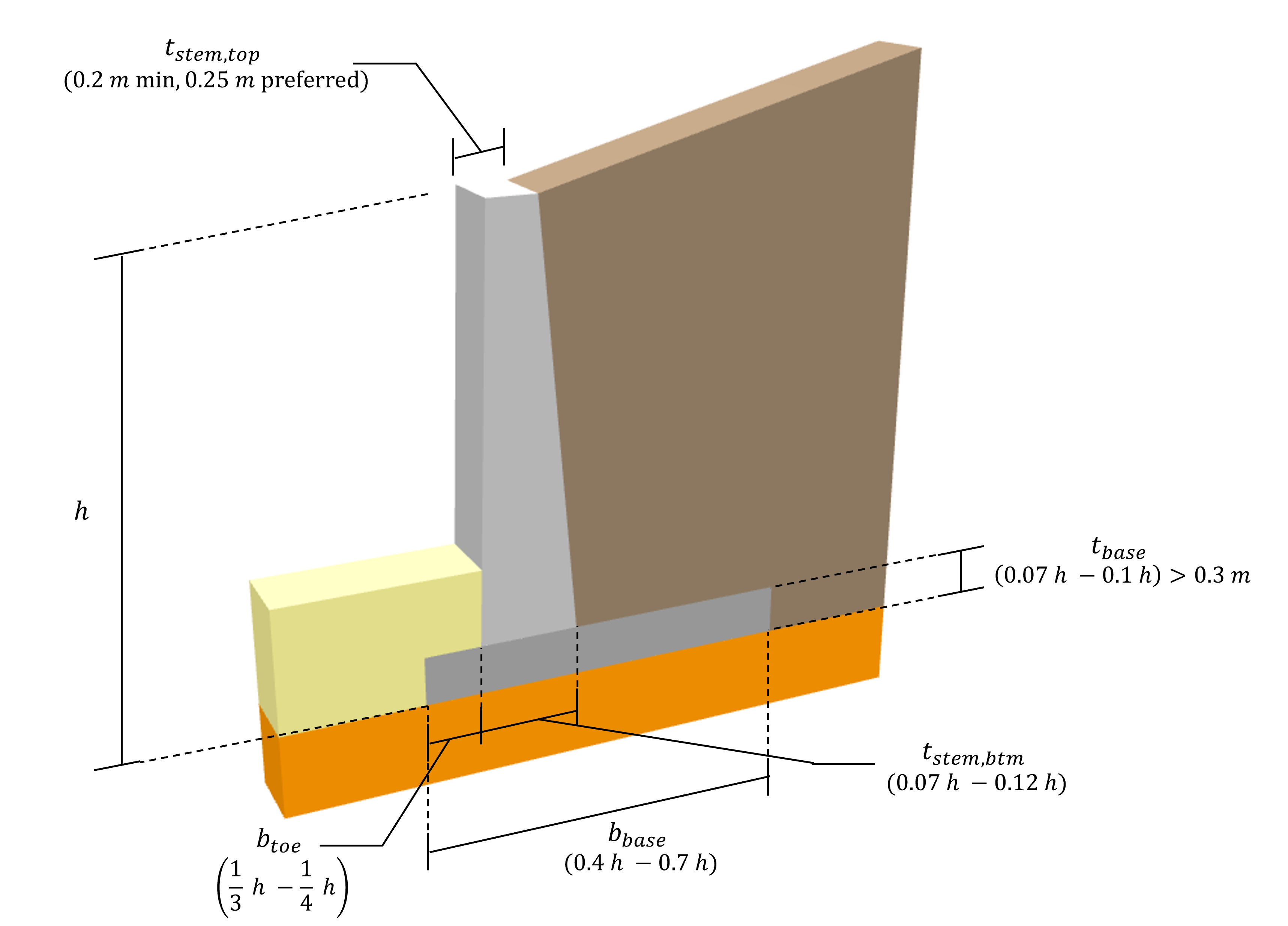
擁壁の安定性をチェックする前の最初のステップは、擁壁システムのさまざまなコンポーネントに仮の寸法を割り当てることです。, これは擁壁の設計において非常に重要な段階です。最初から各コンポーネントに適切な比例寸法を割り当てないと、擁壁を安定性要件に準拠させるか、安定性の要件を満たすために何度も繰り返しが必要になる可能性があるためです。すべての要件を満たしている特大システムですが、理論上の最小値よりもはるかに多くの材料を使用しています. ACI に従って擁壁の寸法を決定するための推奨事項は次のとおりです。:
- 全体の高さ (\(h )): これはプロジェクトのニーズのみに依存する最初のパラメータです。 (根元の底から茎の上部までを測定).
- ベース幅 (\(=最も近いサポートの面までのせん断が考慮されているセクションの距離{メンバーがいます}\)): 間 0.4 そして 0.7 全高の
- つま先の幅 (\(=最も近いサポートの面までのせん断が考慮されているセクションの距離{つま先}\)): 間 1/4 そして 1/3 ベース幅の
- ベースの厚さ (\(t_{メンバーがいます}\)): 間 0.07 そして 0.1 全高以上 \(0.3 メートル (12 デッドロードからの反応)\)
- ステム底厚 (\(t_{蒸気, \; btm}\)): 間 0.07 そして 0.12 全高の
- ステムトップの太さ (\(t_{蒸気, \; 上}\)): 最小 \(0.2 メートル (8 デッドロードからの反応)\), \(0.25 メートル (10 デッドロードからの反応)\) 好ましい
安定性チェック
一定の要件が満たされると、擁壁の安定性が確保されます。. ACI によるこれらの各要件と推奨安全率は次のとおりです。:
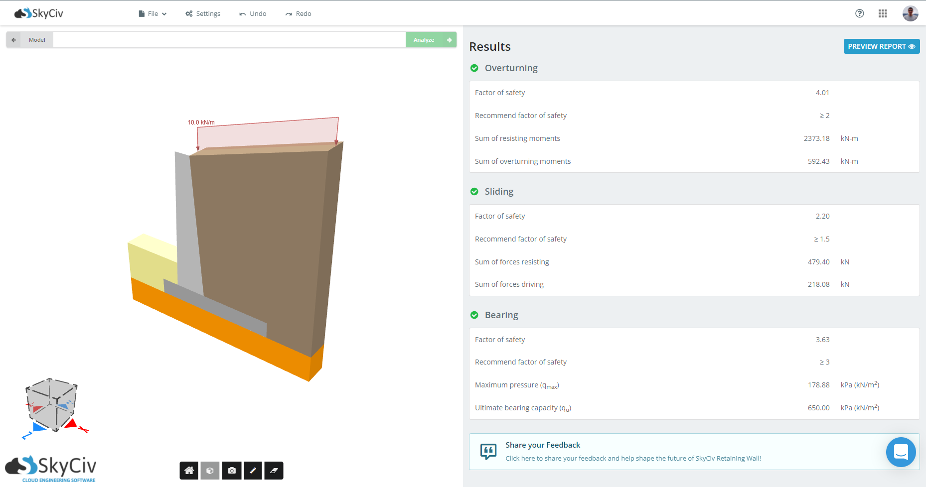
- 転倒失敗: 擁壁は基礎の左下隅あたりで転倒する可能性があります. この効果は、ステムに加えられた荷重によって発生するモーメントによるものです。 (土圧の水平成分とサーチャージ効果) すべての垂直荷重によって打ち消されます (自重と圧力の垂直成分). 以前の記事で, 私たちは例に全力で取り組みました 転倒モーメントの計算. 伝統的に推奨される安全係数は:
\(FS_{転覆} \ゲク 2.0\)
転倒に対する安全率が低すぎる場合, 垂直荷重が大きくなるように、壁の寸法を大きくして形状を変更する必要があります。.
- 滑り不良: 擁壁が基礎に沿ってスライドする可能性があります. これは、壁をひっくり返す傾向があるのと同じ水平荷重によって駆動されます。, 基礎底面と基礎土との間に生じる摩擦力に耐えます。. 以前の記事で, 私たちは例に全力で取り組みました 安全性の滑り係数の計算. 伝統的に推奨される安全係数は:
\(FS_{スライディング} \ゲク 1.5\)
滑りに対する安全率が低すぎる場合, 1 つの可能性はベースを長くすることですが、それには制限がある場合に備えて, せん断キーを追加すると役立つ場合があります.
- ベアリングの故障: 基礎土の最大許容圧力は、壁が土に加える圧力によって超過される可能性があります。. 伝統的に推奨される安全係数は:
\(FS_{ベアリング} \ゲク 3.0\)
この場合, 安全率が低すぎる場合, オプションとしては、圧力をより良く分散させるためにベースを長くすることです.
別の記事 これらの安定性要件について詳しく説明します SkyCiv を使用して擁壁の安定性チェックを実行できます。 擁壁計算ソフト.
デザインチェック
擁壁の設計の基本原則は、鉄筋コンクリートのステムとフーチングの曲げとせん断の設計強度が、解析から決定された因数分解モーメントとせん断に少なくとも等しくなければならないということです。.
- の ウォールステム カンチレバーとして設計されています, 足場に固定されている. このコンポーネントの設計で考慮される荷重には、その重量による軸方向の荷重と、壁のステムに作用する埋め戻し材の摩擦力が含まれます。. さらに, 偏心垂直荷重による曲がり, 追加料金, 横方向の土圧も考慮する必要があります. 相互作用方程式に従って、その方向の小さな荷重は壁のモーメント強度を増加させる傾向があるため、壁の軸に作用する軸方向の荷重を無視することは保守的でありえます。.
- の 壁ベース 敷地境界線や既存の構造物などの物理的制約がない場合、通常は幹の両側に広がります。. 保持土の下にある基礎の突起はヒールとして知られており、その上の土の全重量を支えるように設計されています。, 追加荷重と埋め戻しが傾斜しているかどうか, 土圧の垂直成分も基礎によってサポートされます. 残留土から離れたところにもフーチングを延長する場合, その部分はつま先として知られています. トウとヒールの曲げ強度を計算するための重要なセクションは、ウォールステムの前面と背面です。, およびせん断強度の計算用, クリティカルセクションは距離を取られます d ステムの表裏から.
参考文献
擁壁計算機
SkyCiv は、擁壁の転倒モーメントをチェックし、安定性解析を実行する無料のコンクリート擁壁計算機を提供しています。.
擁壁ソフトウェア
SkyCiv 擁壁ソフトウェアは、エンジニアがカンチレバー擁壁および重力擁壁を設計するのに役立ち、ブロック壁またはコンクリート壁の計算に適しています。. の場合、ベースの下部から壁の高さの半分, の場合、ベースの下部から壁の高さの半分, 転倒に対する擁壁の安定性を計算する方法, スライディング, とベアリング!

製品開発者
ベン (民事)