単一プレート接続は、一部で説明されている 5 つの基本的なせん断接続タイプの 1 つです。 10 の 15第 2 版 AISC マニュアル. この接続タイプはコスト効率が非常に高いため、製造業者に人気があります。. プレートは常にサポートに工場溶接されており、通常は 現場ボルト締め 接続梁まで. 特に工場溶接されたフレームアセンブリでは、プレートを接続ビームに溶接することもできます。. ここにヒントがあります, 現場で行うことを意味する場合は、プレートを接続ビームに溶接しないでください. 現場溶接は労働集約的であるため、非常に高価です.
2 つの構成タイプ
-
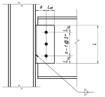
従来構成
- ボルトの垂直方向の列は 1 列のみ許可されます. 接続内のボルトの数は、 2 そして 12.
- ボルト ラインからウェルド ラインまでの距離は、以下でなければなりません。 3-1/2 に.
- 標準穴 (STD) または水平の短い長穴 (HSSL) 表に記載されているように使用することが許可されています 10-9 第 15 版 AISC マニュアルの.
- 垂直エッジ距離は、AISC 仕様表 J3.4 の要件を満たす必要があります。. 水平エッジ距離は、プレートとビーム ウェブの両方で 2d 以上である必要があります, ここで、d はボルトの直径です.
- プレートの厚さまたはビーム ウェブの厚さのいずれかが、表に示す最大厚さの要件を満たす必要があります。 10-9 第 15 版 AISC マニュアルの.

-
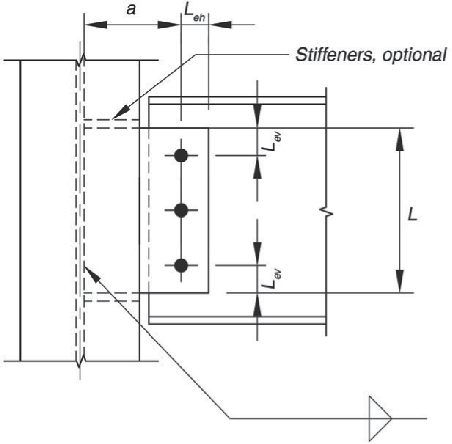
拡張構成
- ボルトの数に制限はありません.
- ウェルド ラインからサポートに最も近いボルト ラインまでの距離は制限されません。.
- 穴の使用は、AISC 仕様セクション J3.2 の要件を満たす必要があります。.
- 水平および垂直エッジ距離は AISC 仕様表 J3.4 要件を満たさなければなりません.

今すぐソフトウェアを使用する.
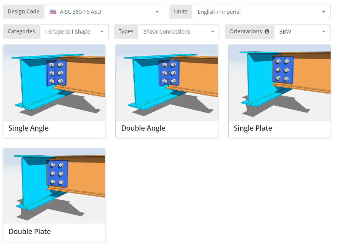
設計コードはAISCにすることができます 360-16 ASDまたはLRFD. 単位はイングリッシュ/インペリアルまたはSI/メトリック. 方向は BCF のいずれかです, BCWまたはBBW. 詳細については、ツールチップにカーソルを合わせてください. 今すぐクリックしてください “シングルプレート” タイル.
[プロジェクト]タブ
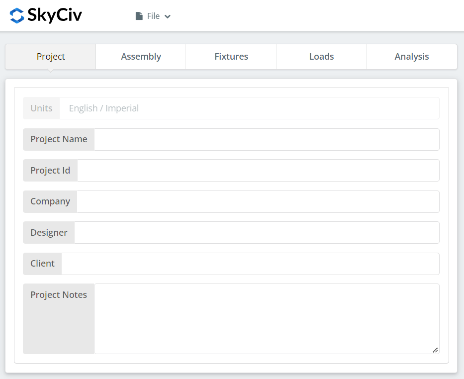
ここでは、現在取り組んでいるプロジェクトの詳細を指定できます.
アセンブリ タブ
[アセンブリ] の下に 3 つのタブがあります. ここで桁を指定します, ビーム, と接続 (シングルプレート) プロパティ.
桁タブ
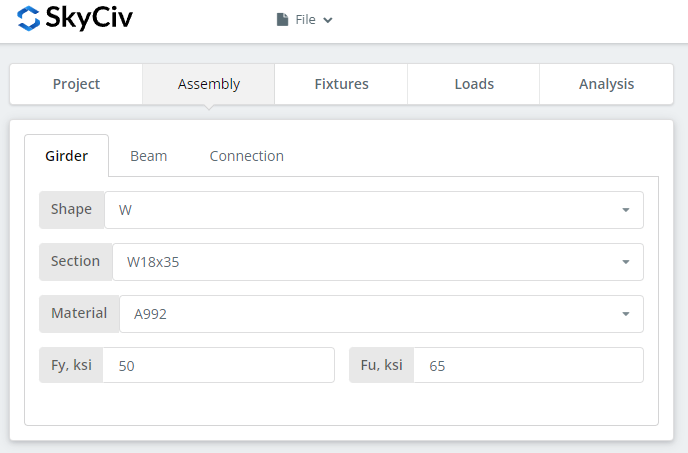
ここでは、桁の断面/形状とその材料グレードを指定できます. A992 または A36 材料を選択できます. でも違う素材を使うなら, [カスタム] を選択して、Fy と Fu の値を手動で入力できます.
梁タブ
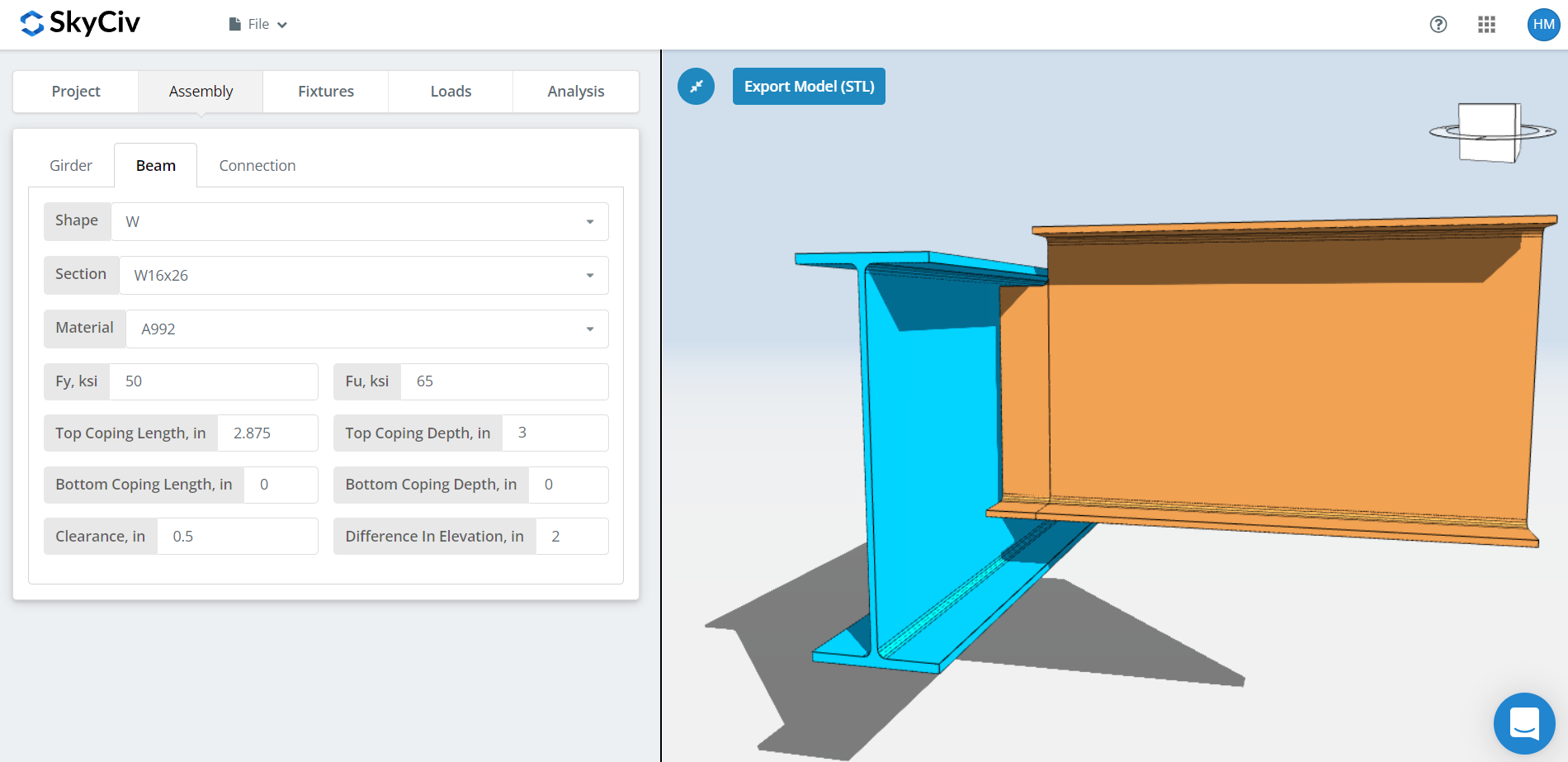
桁タブに類似, ここでは、梁の断面/形状と材料グレードを指定できます. 加えて, コープの寸法、梁のクリアランス、高低差を指定することもできます. BBW向きの場合, 自動対処がありますが、これを好みに合わせて変更することもできます. いずれかの梁セクションを変更するたびに、自動コーピングが再計算されることに注意してください。, 桁断面, クリアランス, もしくは高低差. 梁がまだ桁の内側にあるほど小さいクリアランスを選択した場合, これは、桁フランジが十分に広く、ボルトと桁ウェブとの間の距離が 3-1/2 より大きい場合を除き、ほとんどの場合、従来の単一プレート構成になります。″. さもないと, 梁が桁フランジの完全に外側にあるクリアランスは、自動的に拡張単板構成になります。. 高低差については, 正の値は梁が桁の上にあることを意味し、下の場合は負の値です.
接続タブ
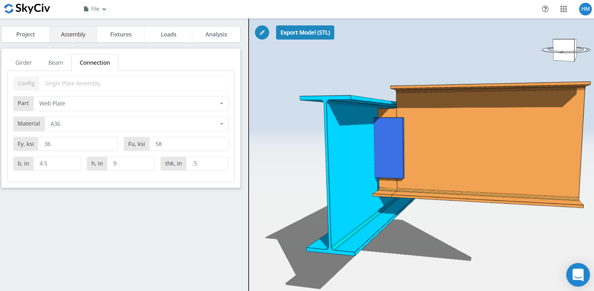
ここでは、ウェブ プレートまたは単板のプロパティを指定できます。. A36またはA992の材料グレードですが、指定することもできます “カスタム” Fy と Fu を手入力する. プレート幅「b」を設定します, プレートの高さ「h」, と板厚「thk」. ここで、3D レンダラーをよく見て、プレートの寸法が適切であることを確認することを忘れないでください。. プレートの高さはビームの深さ以内である必要があり、プレートの幅は、特に拡張プレート構成の場合にビームをボルトまたは溶接するのに十分な幅である必要があります。.
備品 1 タブ
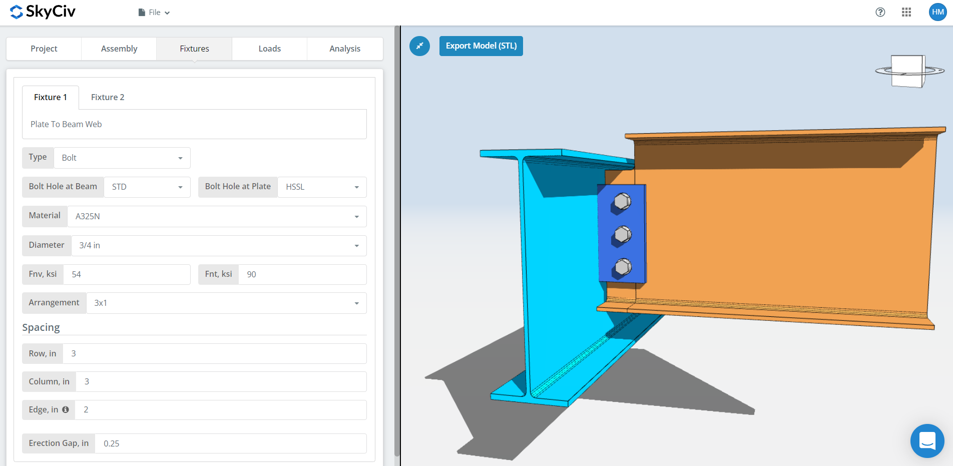
ここでプレートと梁のウェブ接続を指定できます. ボルト固定または溶接のいずれかを選択できますが、このデモンストレーションでは, ボルト締めのものを選びましょう.
最初, 梁とプレートの両方でボルト穴のタイプを指定してください. 製造者は通常、標準の穴を使用することを好みます (STD) ビームおよび水平ショートスロット (HSSL) プレートに穴があり、現場での取り付けが容易になります.
次, ボルトの材質またはグレードを選択してください. A307のどちらかを選択できます, A325, A490, またはカスタム入力. ベアリングタイプの接続には N または X ボルト、滑りが重要な接続には SC. 滑りが重要な接続では、一般的にボルト容量が少ないことに注意してください。. SC は、力の方向に滑りが想定される場合にのみ使用してください。. この具体的な例では, ビームまたはプレートのいずれかで OVS 穴を使用する場合, ボルトはスリップクリティカルとして自動的にチェックされます. N対Xに関しては, X はより大きなボルトせん断能力を持っていますが、ボルトのねじ山がせん断面から除外されていることを確認する必要があるため、これをエレクターと適切に伝える必要があります。. そしてSCに関しては(あ) 対SC(B), これは、提案された根太の最大深さが、選択した根太のスパンと荷重の場合に対して小さすぎる場合に発生します。(B) ボルトの容量は大きくなりますが、プライのより徹底的な洗浄も必要になります。, 例えば, SSPC-SP6 または市販のブラスト洗浄.
次, ボルトの直径を指定してください. 5/8からお選びいただけます″ 1-1/2まで″ 直径または同等のメートル単位. その後, ボルトの配置を指定してください. まで選択できます 12 行と列をボルトで固定する. ボルトの行と列の間隔も忘れずに指定してください. ここにヒントがあります, より多くのボルト容量が必要な場合は、ボルトの数を増やす代わりに、より大きなボルト間隔を使用できます. プレートの高さが適切で、許容されるビームの深さの範囲内であることを確認してください. 私たちのボルトグループの強みは、 瞬時回転中心法 (ICOR), これは、任意のボルト間隔を指定して、ボルト容量の増加を利用できることを意味します. しかし, 製造業者が可変ボルト間隔に問題がないことを確認する必要があります. 一部の製造業者は 3 を使用することを好みます″ 典型的な間隔. に関しては “縁” 入力, これは、梁の端から最初のボルト柱までの距離です。.
そして最後に, 勃起ギャップ. その名の通り, これは現場での勃起を助けるための隙間です. ボルトの容量も同等に減少するため、このギャップが本当に必要であることを確認してください。.
備品 2 タブ
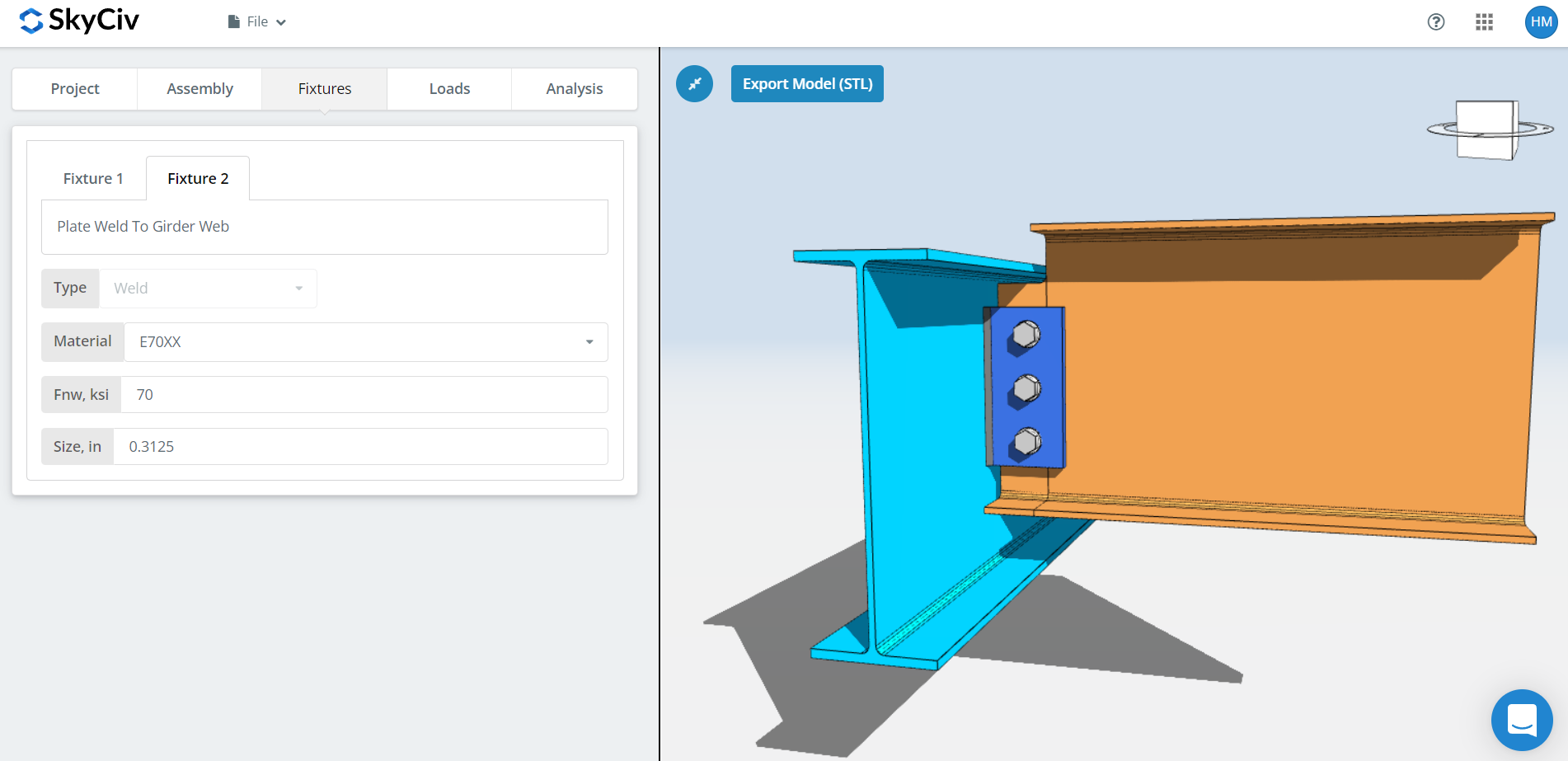
ここでサポートするプレートを指定できます (桁ウェブ, 柱フランジ, またはコラムウェブ) 繋がり. 単板接続の場合、ここでは溶接のみを選択できます. 最初, 溶接材料を指定してください. 溶接材料のオプションはいくつかありますが、既存の材料が存在しない場合は、, 「カスタム」を使用できます’ そして手動でFnwを入力してください. そして最後に, 溶接サイズを忘れないでください. 単板接続用, 少なくとも次の溶接サイズが必要です。 5/8 板厚の倍. これは、溶接部がプレートの能力を確実に発揮できるようにするためです。. ここにヒントがあります, 表を参照 8-12 第 15 版 AISC のページ 8-126. 5/16 から溶接パス数が大幅に増加″ 3/8まで″ すみ肉溶接. 5/16 のパスは 1 枚だけ必要です″ しかし3/8に3パス″. つまり、, 1/2にこだわってみてください″ 5/16 だけで済むので厚いプレートを使用します。″ それを発展させるためのすみ肉溶接. プレートの厚さを増やす前に、まずプレートの高さを最大許容高さまで増やしてみてください。これは、プレートが厚いほど、それを開発するためにより大きな溶接が必要になり、場合によっては複数の溶接パスが必要になるためです。. 溶接パスが複数あると、溶接デポジットが多くなり、労働時間が長くなり、コストが高くなります.
「荷重」タブ
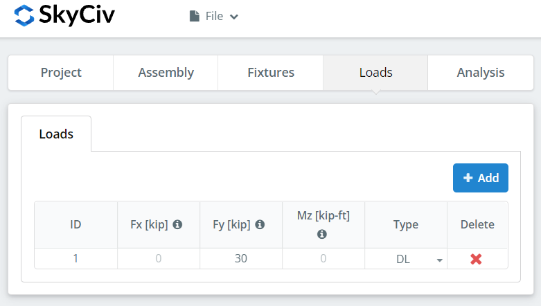
「Fy」に垂直せん断荷重を忘れずに入力してください。.
「分析」タブ
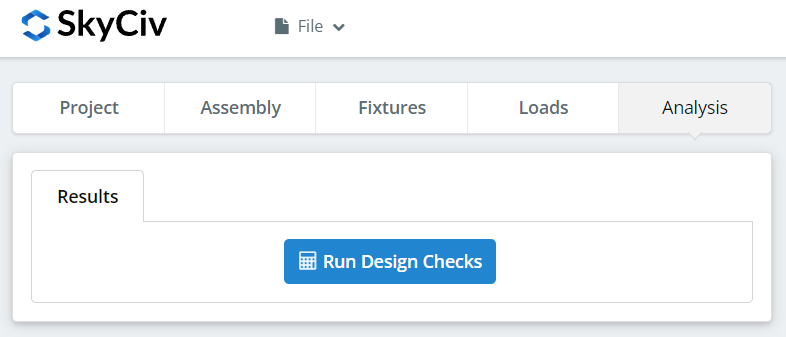
そして最後に, クリック “デザインチェックを実行する”. 前のタブで必要な入力を見逃した場合, これにより、不足している入力を埋めるように通知されます.
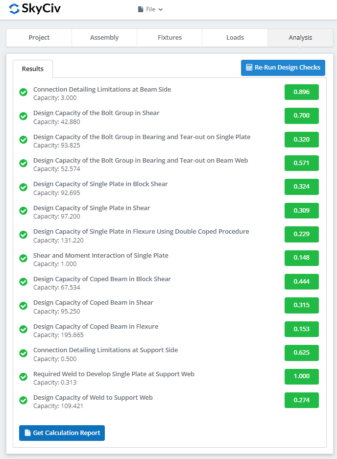
クリックした後 “デザインチェックを実行する”, 接続が失敗したかどうかの概要を確認できます. 失敗した場合, 前のタブの入力を手動で変更してから、, クリック “設計チェックを再実行する”. ようやく大丈夫になったら, クリック “計算レポートの取得” 詳細レポートを見るには.
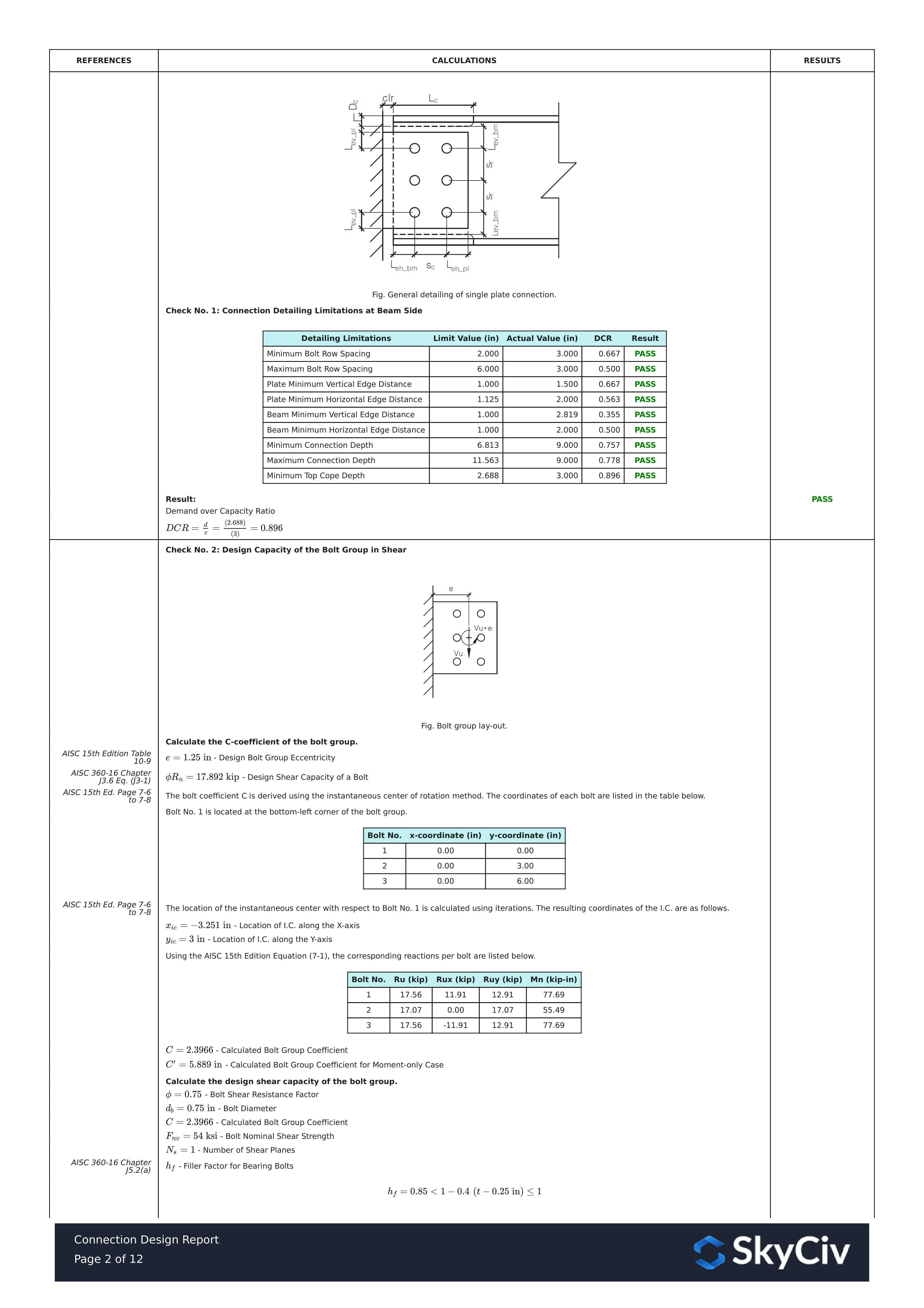
上に表示されているのは、詳細な計算レポートの一部です。. ご覧のように, AISC マニュアルおよび/または仕様への参照がある. これにより、署名エンジニアが計算をクロスチェックしやすくなります。. 私たちの計算は非常に読みやすいです. 説明書に書いてあることと同じように書いてあります, 仕様, またはデザインガイド.
詳細な計算レポート全体の PDF コピーはこちらです… 接続設計レポート. 見てみな!