
以前の記事を読んだら, AISC 360: せん断接続設計, AISC に基づいてシンプルな接続がどのように設計されているかがよくわかるでしょう。 360. せん断接続はビーム端反力を提供するだけで済みます. 瞬間的なつながりは、その反応とそれに伴う終わりの瞬間を届けなければなりません, 支柱が問題になる. この記事では、2 つの I 字型部材間のモーメント接続の例を取り上げ、満たす必要がある設計基準について説明します。. また、同じ結果を直接得ることもできます。 SkyCiv接続設計 モジュール, これらの接続をチェックします AISC 360-16 ASD または LRFD の場合.
せん断接続の例のように, ここでの計算では許容応力設計を使用します。 (ASD) 方法. 構造設計におけるASDとLRFDの違いに精通していない場合, 必ず 私たちのビデオをチェックしてください これを説明する.
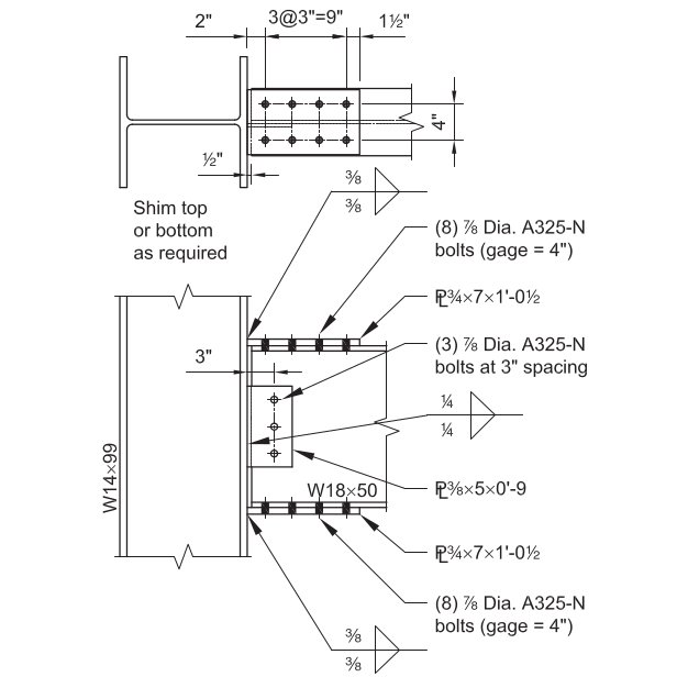
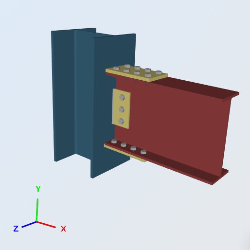
この例では, ボルト締めの能力を評価します フランジメッキ 完全拘束 (NS) モーメント接続 W18x50の梁とW14x99の柱の間, 寸法を使って, 溶接と荷重を以下に示します. 接続はビーム端の垂直反力と発生した端モーメントをサポートする必要があります。. せん断接続との比較, 違いは、梁フランジの力を支柱フランジに伝える一対のプレートです。.
フランジ プレートは、ビームの端モーメントを引張と圧縮のカップルに変換します。. 天板が引っ張られる, 底板が押す, そして両方の力が集中力として柱フランジに加わります。. そのため、モーメント接続には、せん断接続が行われていないことを列ローカルでチェックする必要があります。.
与えられた:
サービスレベルの負荷 & 素材:
デッドロードからの垂直せん断 (VD) = 7.0 キップ
ライブロードからの垂直せん断 (VL) = 21.0 キップ
デッドロードからの瞬間 (MD) = 42.0 キップフィート
ライブロードからの瞬間 (ML) = 126.0 キップフィート
プレート素材: ASTM A36, Fy = 36 KSI, フー= 58 KSI
梁と柱の材料: ASTMA992, Fy = 50 KSI, フー= 65 KSI
梁と柱の形状:
ビーム: W18x50; bf = 7.50 に, tf = 0.570 に, d = 18.0 に, tw = 0.355 に, Sx = 88.9 in ^ 3
カラム: W14x99; bf = 14.6 に, tf = 0.780 に, d = 14.2 に, tw = 0.485 に, kdes = 1.38 に
フランジプレート: 3/4 厚く; 7.0 xで 12.5 寸法で
ウェブプレート: 3/8 厚く; 5.0 xで 9.0 寸法で
備品 (ボルトと溶接):
フランジ: (8) – 7/8-に.-標準穴の直径 ASTM F3125 グレード A325-N ボルト
ウェブプレート: (3) – 7/8-に.-標準穴の直径 ASTM F3125 グレード A325-N ボルト
70-ksi電極フィレット. A325 および A490 は ASTM F3125 内のグレードです。, 古いスタンドアロンのボルト仕様を統合しました。.
負荷計算:
LRFD 負荷 (参照のみ):
究極の垂直反力 (Rあなた) = 1.2 (7.0 キップ) + 1.6 (21.0 キップ) = 42.0 キップ
究極の瞬間 (Mあなた) = 1.2 (42.0 キップフィート) + 1.6 (126.0 キップフィート) = 252.0 キップフィート
ASD 負荷:
許容垂直反力 (Ra) = 7.0 キップ + 21 キップ= 28.0 キップ
許容モーメント (Ma) = 42.0 キップフィート + 126 kip-ft = 168.0 キップフィート
以下のすべてが ASD 負荷に対してチェックされます. 2 つの方法を分離してください: ASD はサービス負荷と許容強度を比較します, LRFD は因数分解荷重と設計強度を比較します, 上記の LRFD 数値は、2 つを比較できるようにするためにのみ掲載されています。.
SkyCiv接続設計ソフトウェアに基づくソリューション:
正誤表: この例のフランジプレートの幅は 7.0 に しかし、計算に使用される幅は 7.50 に, したがって、値の違い.
フランジフォース
以降のすべてのチェックは 1 つの数字によって駆動されます, フランジプレートにかかる力. 終了の瞬間は、プレートの重心で作用するカップルに分解されます。, したがって、レバーアームはビームの深さにプレートの厚さを 1 枚加えたものになります。:
Pの = [ 168.0 キップフィート (12 インチ/フィート) ] / (18.0 に + 0.75 に) = 107.5 キップ
W14x99フランジへのフランジプレート, 溶接強度
フィレット溶接の強度, Ω= 2.0
溶接サイズ, t = 0.375 に
Fnw = 0.6 FEXX [ 1.0 + 0.5 それなし1.5 (θ) ]
どこ, θ=荷重が溶接軸となす角度
= 90, 横方向に荷重がかかる溶接用
= 0, 縦方向に荷重がかかる溶接用
溶接の単位サイズあたりの強度:
許容溶接応力, Faw = 0.6 (70KSI) / 2.0 = 21 KSI
横方向の長さ, lt = 7 に
縦方向の長さ, ll = 0 に
総有効長, l = lt (1.5) + ll (1.0) = 10.5 に
の 1.5 横方向の長さによって方向強度が増加します, 1.0 + 0.5 それなし1.5(90).
(Ra / a) = 21 KSI (10.5 に) = 220.5 キップ / に
有効サイズ (喉) フィレット溶接の, a:
0.707 =のコサインまたはサイン 45 度
a = (0.707) t = 0.265 に
2 つの溶接, プレートの両側に1つずつ:
Ra = (Ra / a) a (2) = 220.50 (0.265 に) 2 = 116.9 キップ
設計容量比, DCR:
必要な負荷, R = 107.5 キップ
全体の容量, Ra = 116.9 キップ
DCR = (107.5 / 116.9) = 0.919, わかった
列のローカルチェック
これら 4 つのチェックでは、W14x99 が局所的な硬化なしでフランジの力を受け入れることができるかどうかを確認します。. それらはすべて同じフランジ力に対して比較されます:
フランジフォース, Pの = 107.5 キップ
- Webローカル降伏, Ω= 1.5
Rん / Ω= [ Fは tw (5k + lb) ] / Ω= 50ksi (0.485に) [ 5(1.38に) + 0.75に ] / 1.5 = 123.7 キップ
ここに tw は柱ウェブの厚さ、 lb ベアリングの長さ, フランジ板厚とする.
設計容量比, DCR:
フランジフォース, Pの = 107.5 キップ
全体の容量, Ra = 123.7 キップ
DCR = (107.5 / 123.7) = 0.869, わかった
- フランジローカル曲げ, Ω= 1.67
Rん / Ω= [ 6.25 Fそして tf2 ] / Ω = [ 6.25 (50KSI) (0.78に)2 ] / 1.67 = 113.8 キップ
設計容量比, DCR:
フランジフォース, Pの = 107.5 キップ
全体の容量, Ra = 113.8 キップ
DCR = (107.5 / 113.8) = 0.944, わかった
- Webローカルの不自由, Ω= 2.0
Rん / Ω= 0.8 tw2 [ 1 + 3 ( lb / d ) ( tw / tf )1.5 ] ( E Fそして tf / tw)0.5 / Ω
= 0.8 (0.485に)2 [ 1 + 3 (0.05) (0.62)1.5 ] [ (29000KSI) (50KSI) (0.78に) / 0.485に ] 0.5 / 2.0
= 154.8 キップ
設計容量比, DCR:
フランジフォース, Pの = 107.5 キップ
全体の容量, Ra = 154.8 キップ
DCR = (107.5 / 154.8) = 0.694, わかった
- Web圧縮座屈, Ω= 1.67
Rん / Ω= [ 24 tw3 ( E Fそして )0.5 / h ] / Ω
= 24 (0.485に)3 [ (29000KSI) (50KSI) ] 0.5 / 14.2に (1.67)
= 139.0 キップ
ここでは、列全体の深さが代わりに使用されます。 h, フランジ間の明確な距離からフィレットを差し引いたもの, どちらが保守的ですか.
設計容量比, DCR:
フランジフォース, Pの = 107.5 キップ
全体の容量, Ra = 139.0 キップ
DCR = (107.5 / 139.0) = 0.773, わかった
4 つの列のローカル チェックのどれも管理しない, したがって、W14x99 は、これらの限界状態では横方向補強材なしでフランジ力を受けます。. どれかが超えていたら 1.0, 修正方法は、より大きなフランジ プレートではなく、補強材またはダブラー プレートです。, 不足した容量は列に属するため.
W18x50フランジ, フランジプレート引張降伏
張力における要素の強さ, Ω= 1.67
Rん / モーメント接続と同じ設計上の課題はありませんそして あg / Ω= (36KSI) (7.5に) (0.75に) / 1.67 = 121.3 キップ
設計容量比, DCR:
フランジフォース, Pの = 107.5 キップ
全体の容量, Ra = 121.3 キップ
DCR = (107.5 / 121.3) = 0.887, わかった
W18x50フランジ, フランジプレート圧縮降伏
圧縮における要素の強度, Ω= 1.67
Rん / モーメント接続と同じ設計上の課題はありませんそして あg / Ω= (36KSI) (7.5に) (0.75に) / 1.67 = 121.3 キップ
ベアリングのボルト穴が埋められているため、コンプレッションプレートは総断面で確認されます。. プレートが柱面と最初のボルト線の間で十分に短く、細さを損なわないため、張力降伏値と一致します。.
設計容量比, DCR:
フランジフォース, Pの = 107.5 キップ
全体の容量, Ra = 121.3 キップ
DCR = (107.5 / 121.3) = 0.887, わかった
W18x50フランジ, フランジプレート引張破壊
破裂における要素の強さ, Ω= 2.0
せん断遅れ係数, U AISC仕様表D3.1から: 1.0
Rん / モーメント接続と同じ設計上の課題はありませんあなた あe / Ω= (58KSI) [ 7.5に – 2 (1に) ] (0.75に) (1.0) / 2.0 = 119.6 キップ
プレート幅全体で 2 つの穴が差し引かれます. の 1 控除の中で、 7/8 ボルト径プラスで 1/8 に, これは、ネット領域に使用される標準の穴の許容値です。.
設計容量比, DCR:
フランジフォース, Pの = 107.5 キップ
全体の容量, Ra = 119.6 キップ
DCR = (107.5 / 119.6) = 0.899, わかった
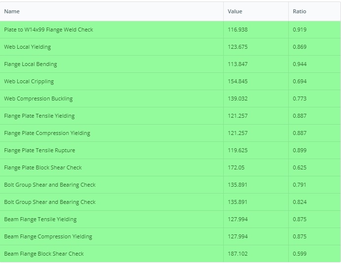
すべての結果チェックの要約表
以下は、この接続に必要なすべての設計チェックのSkyCiv接続設計モジュールの概要表です。. これらのチェックのすべてがこの記事に示されているわけではありませんが、PDFで入手できます。PDFはここからダウンロードできます。: 接続-設計-レポート-例II.B-1-ASD
上記で実行されたチェックのうち、, フランジの局所的な曲げが影響する 0.944. ビーム終了モーメントが伸びるならそっちが注目だ, それは列プロパティです, したがって、より重いフランジプレートは役に立ちません.
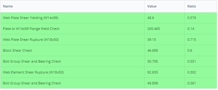
同様に, LRFDバージョンの例はこのリンクにあります: 接続-設計-レポート-例II.B-1-LRFD
この例を自分で実行してください
W18x50を入力してください, W14x99とフランジプレート, そしてモジュールは、上記のすべてのチェックをその使用率とその背後にある句とともに返します。. ブラウザ上で動作します, インストールするものが何もない状態で.

参考文献
- AISC 360-16, 構造用鋼製建物の仕様
- AISC設計例v14.1 (例II.B-1, IIB-2ページから 13)
- SkyCiv接続設計ソフトウェア: https://skyciv.com/structural-software/connection-design/
- フランジプレート接続計算機: https://skyciv.com/structural-software/connection-design/flange-plate-connection-calculator/
