この記事の目的は、 SkyCiv Foundation に使える この記事の目的は、. これも: 耐圧に対するサービスレベル容量の計算, 足場の安定性, 足場の大きさ; 基礎の厚さと補強の強度レベル. この記事の目的は、, この記事の目的は、.
プロジェクトの背景
この注目のプロジェクトは、によって設計および構築されました ベータクワッド建設サービス株式会社, ルソン島中部に位置します, フィリピン. 商業用セメント生産に使用されます, 1日あたりの生産能力がある 30,000 メートルトン. 建設中のプロジェクトの全体的なフットプリントは約 800 メートル2. 以下を参照, 構造のスチール部分は横方向の耐荷重フレームとして機能します。 (3F(メザニン付き)). このプロジェクトのすべてにおいて、 43 構造設計に必要な独立基礎.
Foundation の設計に適用された設計コードのベースは NSCP でした 2015. NSCP 2015 ACIに似ています 318-14 コード , どのACI 318-14 SkyCiv財団設計モジュールで利用可能です.
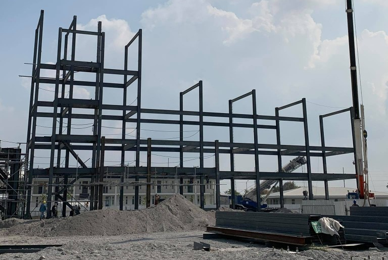
図 1 : 工事中の現場写真
SkyCiv モデルとパラメータ
上記の構造をモデル化すると、 SkyCiv構造3D プラットフォームは、デザイナーが 各種モデリングツール すべての SkyCiv ユーザーが利用できます.
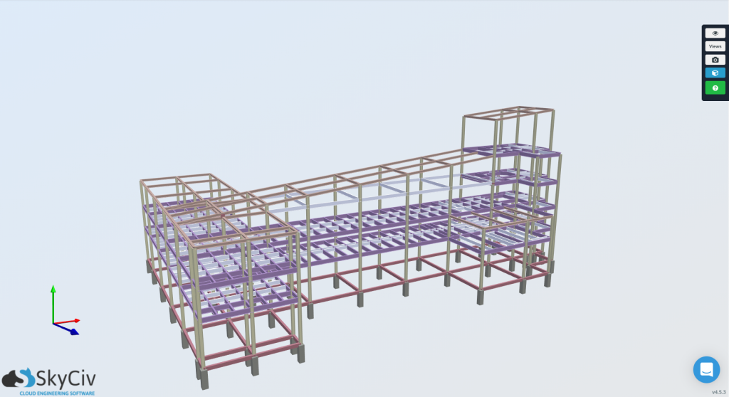
図 2 : 3D SkyCiv 構造 3D モデルのレンダリング
この記事の目的は、
基礎設計の場合, 独立基礎設計に必要な最も重要な建物パラメータは、敷地の耐震特性です。, およびフーチングの材料特性. ルソン島中部のこのプロジェクトの場所について, フィリピン, 対応する地震帯は 地震ゾーン 4.
この記事の目的は、, 20.68 MPa この記事の目的は、 415 MPa この記事の目的は、. この記事の目的は、, この記事の目的は、, これらの材料特性が正しく入力されていること, これらの材料特性が正しく入力されていること.
これらの材料特性が正しく入力されていること
これらの材料特性が正しく入力されていること, これらの材料特性が正しく入力されていること. これらの材料特性が正しく入力されていること, これらの材料特性が正しく入力されていること:
これらの材料特性が正しく入力されていること 2 メートル
土壌支持力 = 192 KPa.
これらの材料特性が正しく入力されていること 16 kN / m3
これらの特性は、あらゆるタイプの基礎を設計するときに必要です。, これらの特性は、あらゆるタイプの基礎を設計するときに必要です。.
荷重の組み合わせ
SkyCiv Foundation Design Module は基本的な荷重の組み合わせを実行でき、サービス荷重と因数分解荷重として表されます。. また, 設計モジュールは、地震荷重が加わったときに自動的に地震パラメータを考慮します。 (E) 入力に任意の値がある.
地盤工学設計用 (サービスレベル):
地盤工学設計に適用可能な荷重の組み合わせ, これらは両方の ASCE に適用されます 7-10 とNSCP 2015 デザインコード, 次は次のとおりです:
[1] D + L
[2] D + L + E/1.4
[3] D + E/1.4
構造設計用 (因数分解レベル):
両方の ASCE に適用できる構造設計のアプリケーション荷重の組み合わせ 7-10 とNSCP 2015 デザインコードは以下のとおりです:
[1] 1.4D
[2] 1.2D + 1.6L
[3] 1.2D + 1.0E + 1.0L
[4] 0.9D + 1.0E
これらの特性は、あらゆるタイプの基礎を設計するときに必要です。
これらの特性は、あらゆるタイプの基礎を設計するときに必要です。, これらの特性は、あらゆるタイプの基礎を設計するときに必要です。.
これらの特性は、あらゆるタイプの基礎を設計するときに必要です。 & 反応
プロジェクトの基礎を設計するためにFoundationモジュールに入る前に, 各基礎のベースカラムの反応は、構造3Dの解析部分に記録して、基礎設計モジュールに入力できるようにする必要があります。. これらの反応は、構造解析から決定されました. エンベロープ結果の使用, 各財団の最悪のケースが取られました. これらの力は、.CSVファイルを介して簡単に表形式でエクスポートされ、Foundation DesignModuleにコピーされました。.
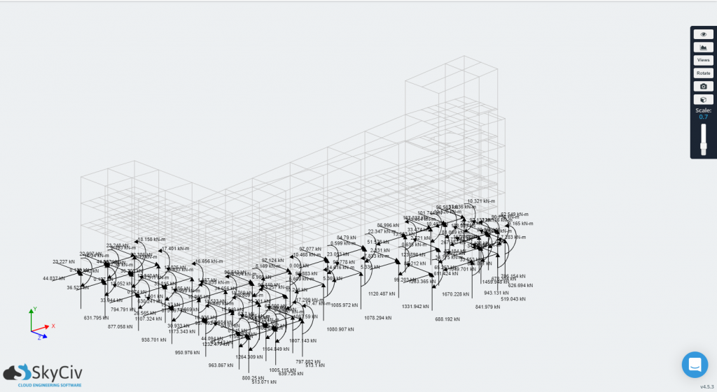
図 3-a: 構造 3D モデルからの柱脚の反応
に 図 3-a, S3D は、抽出して SkyCiv Foundation Design Module にインポートできる反力荷重を表示します。.
入力 & Foundation モジュールの出力
記録された力で, SkyCiv Foundation モジュールを使用して、これらの基礎の設計を分析および確認できます。. このモジュールを使用すると、エンジニアはプロジェクトに必要なだけ多くの基盤を追加できます。. だからこの場合, エンジニアは設計し、チェックしました 43 基礎を独立して. 図 3-b 設計の対象となる基盤が複数ある場合のユーザー インターフェイスとプレゼンテーションを示します。.
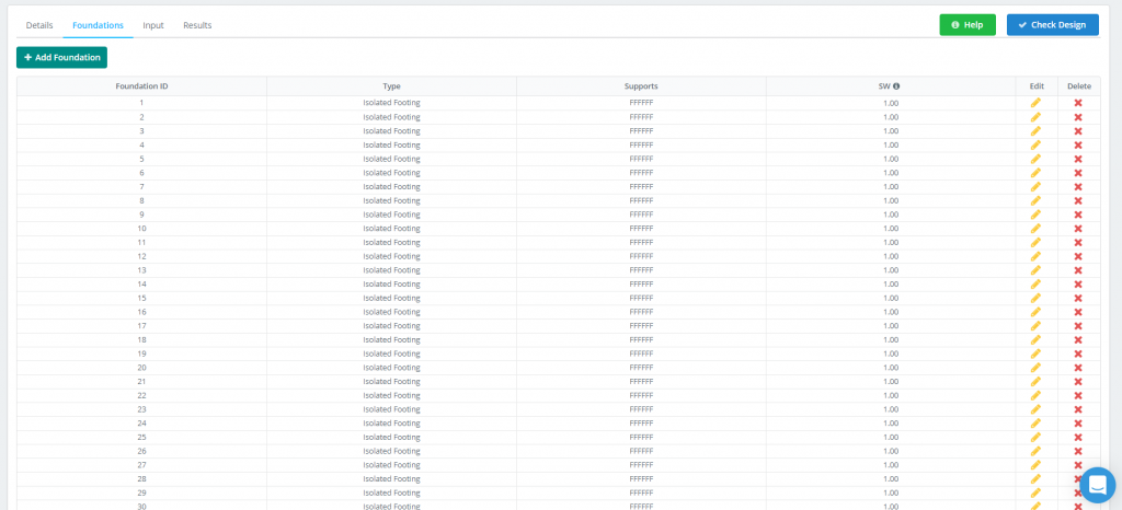
図 3-b: 「基礎設計」タブ
もっと遠く行く, 各基礎デザインには使いやすい機能が組み込まれています。, 線形ワークフロー, 前のステップから記録されたすべての情報を入力できる場所.
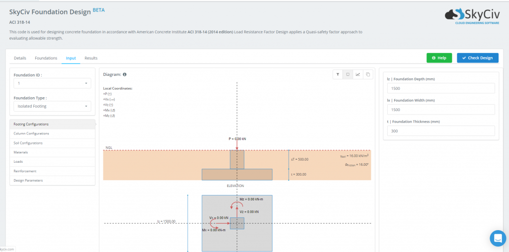
図 3-c: 基礎設計モジュールのユーザー インターフェイス
設計要件が確立され、材料特性と荷重が入力されると、, 基礎を設計する準備ができています. をクリックした後の設計結果のプレゼンテーション デザインを確認する ボタンはで見ることができます 図 3-d. この結果は容易に理解できます, 統一比として表されるため. これらの比率は、個々の制限状態ごとの経験値/キャパシティを表します。. 一つが終わったとわかったとき 1.0, の 状態 足場が赤くなり表示されます “不合格”. さもないと, そのセルは緑色になり、表示されます “パス”. これにより、設計プロセスでどの基礎に微調整やさらなる作業が必要かを簡単に確認できます。.

図 3-d: サンプル設計結果
に示されているように、 図 3-d, 設計中にチェックされる 5 つの異なる限界状態は次のとおりです。:
- フーチングサイズ
- 転倒、滑走などの安定性
- 一方向せん断
- 二方向せん断
- たわみ
各極限状態の統一比をさらに深く掘り下げるには, エンジニアは基礎設計レポートを参照できます, 各財団からアクセス可能. これらのレポートは、プロジェクトで使用するためにエクスポートして使用できる専門的な PDF で図と詳細な手計算を一緒に提供することにより、構造エンジニアリング ソフトウェアのブラックボックスを開きます。. 見る 図 3-e これらのレポートの 1 つがどのように表示されるかを以下で確認します:
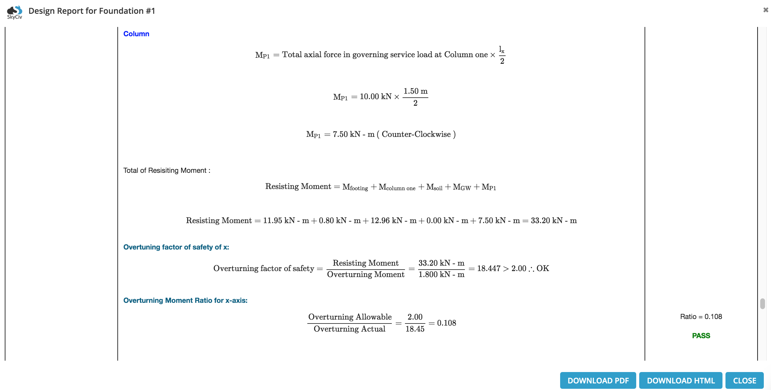
図 3-e: 詳細な基礎設計レポートからの抜粋の例

アルバートパモナグ, 工学修士
構造エンジニア, 製品開発